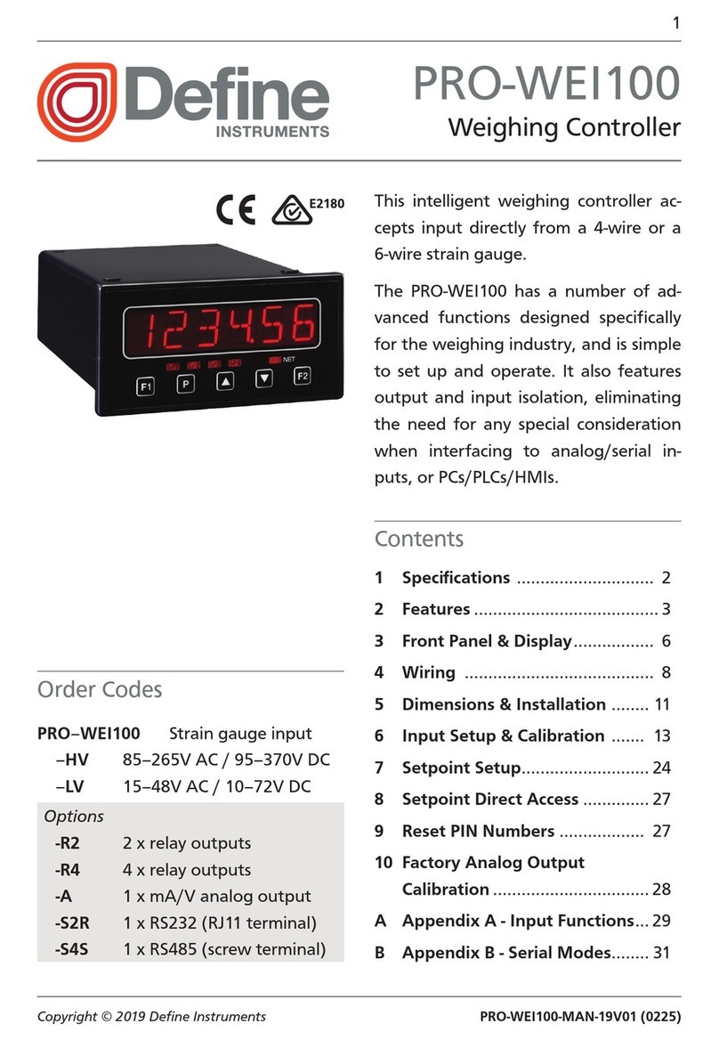
Define Instruments PRO-CTR200 User manual

PRO-CTR-MAN-16V03 (0128)Copyright © 2016 Dene Instruments
1
This advanced controller is ideal for a
wide variety of rate monitoring and
batching applications.
It is available with either a single or dual
display, and has a variety of advanced
features, including: batching, batch
count modication, user programmable
input functions, setpoint tracking, set-
point latching and startup inhibit.
Contents
1 - Specications............................. 2
2 - Display & Front Panel................ 3
3 - Wiring ........................................ 5
4 - Input Header Adjustment......... 9
5 - Dimensions & Installation........ 11
6 - Count Modes ........................... 13
7 - Features ................................... 17
8 - Input Setup & Calibration....... 18
9 - Setpoint Setup......................... 26
10 - Setpoint Direct Access ............ 31
11 - Reset PIN Numbers / View
Firmware Version .................... 31
A - Appendix A - Serial Modes ..... 32
PRO-CTR100/200
Counter/Rate Controller
Order Codes
PRO-CTR100 Single display
PRO-CTR200 Dual display
–HV 85–265V AC / 95–370V DC
–LV 15–48V AC / 10–72V DC
Options
–R2 2 x relay outputs
–R4 4 x relay outputs
–A 1 x mA/V analog output
–S2R 1 x RS232 (RJ11 terminal)
–S4S 1 x RS485 (screw terminal)

PRO-CTR-MAN-16V03 (0128) Copyright © 2016 Dene Instruments
2
1 SPECIFICATIONS
Input
Sensor type Quadrature (x1, x2, x4),
NPN, PNP or TTL
3 x counter inputs available
Input 0–24V DC, 0–30V AC
Power supply HV= 85–265V AC / 95–
370V DC, or LV= 15–48V AC / 10–72V DC
Excitation Default: 24V DC (50mA
max). Optional: 5V DC (200mA max)
Count modes Quad x1/x2/x4,
A+B, A–B, A/B Independent, Up/
Down, C Count, Reset to oset A B,
Reset to oset and start A B
Counter input frequency
10kHz: Quad x4, A+B, A–B, A/B Ind,
Up/Down, RSOFAB, RSOFST
20kHz: Quad x1, Quad x2
38kHz: C Count
Rate input frequency 20kHz max
Minimum pulse width Must be > 5μs
Sampling rate Counter: 10msec
Rate: 100msec
Rate resolution 0.01Hz
Rate accuracy 0.005%
Rate temp. dri Typically 2ppm/°C
Relay Output
Number of relay outputs None, 2 or 4
Relay output type 5A form A (3A 240V
AC max or 3A 30V DC max)
Analog Output
Number of analog outputs None or 1
Analog output type Isolated 16 bit
4–20mA/0–10V
Comm Port
Number of comm ports None or 1
Comm port options
S2R= Isolated RS232, RJ terminal, or
S4S= Isolated RS485, screw terminal
Serial output Custom ASCII, Modbus
RTU slave or Ranger A
Data rate 1200–115k2 baud
Parity Odd, even or none
Programming
Front panel buttons Up, Down, P
(Prog/Enter), plus 2 Menu buttons (F)
Security Input and setpoint setups
are independently accessible and PIN
protected
OPTIONAL
OPTIONAL
OPTIONAL

PRO-CTR-MAN-16V03 (0128)Copyright © 2016 Dene Instruments
3
Display
Display type 14 segment alphanumeric
LED display, 5 buttons
LED indicators 6 setpoint LED's
PRO-CTR100 1 x 6 digits 13mm (0.5")
PRO-CTR200 2 x 6 digits 10mm (0.4")
Display range 0.1 to 99999.9
Construction
Casing Panel mount case
Ingress protection rating IP65 dust/
splash proof (face only)
Dimensions (H x W x D)
48 x 96 x 120mm (1.89 x 3.78 x 4.72")
Panel cutout 45 x 92mm (1.77 x 3.62")
2 DISPLAY & FRONT PANEL
2.1 - Display
Two display types are available for the PRO–CTR controller. Both feature 14 segment
alphanumeric display characters, 6 indicator LEDs and 5 buttons:
PRO-CTR100
›1 x 6 digits 13mm (0.5")
›Customisable display source
(see 8.4B)
›During setup, the text prompt
toggles with selectable
options/values 96mm (3.78")
48mm
(1.89")
PRO-CTR200
›2 x 6 digits 10mm (0.4")
›Customisable display source
for both rows (see 8.4B–D)
›During setup, the top row
displays selectable options/
values, and the bottom row
displays the text prompt
96mm (3.78")
48mm
(1.89")

PRO-CTR-MAN-16V03 (0128) Copyright © 2016 Dene Instruments
4
2.2 - Front panel
SPX /The SP LED's are used to indicate active setpoints.
This button is used to access the Input Setup & Calibration menu (Section 8).
This button is typically used to save your settings and advance to the next step
in the setup process. A custom function can also be programmed (see 8.5B).
This button is typically used to scroll through options or increase values in the
setup menu. Pressing this button from the main display will allow you to view/
reset the Peak value, and view the Rate and Primary Counter values (see 2.3).
This button is typically used to scroll through options or decrease values in the
setup menu. Pressing this button from the main display will allow you to view/
reset the Valley value, and view the B and C Counter values (see 2.3).
This button is used to access the Setpoint Setup menu (Section 9) and the
Setpoint Direct Access menu (Section 10).
2.3 - Up and down button shortcuts
Pressing the and buttons from the main operational display allows instant
access to a number of values held in the controller's memory. These variables will ap-
pear in the order shown in the table below, and will cycle continuously at each press
of the or button. Press at any time to return to normal operating mode.
Up and down button shortcuts
PEAK Maximum measured rate value since the instrument was turned on/reset
PRMCNT Current value of primary counter
RATE Current rate value
VALLEY Minimum measured rate value since the instrument was turned on/reset
B CNT Current value of B counter
C CNT Current value of C counter
PEAK and VALLEY may be reset to zero by pressing the and buttons at the
same time while the variable is being displayed.

PRO-CTR-MAN-16V03 (0128)Copyright © 2016 Dene Instruments
5
2.4 - Display brightness
To adjust the display brightness, press the and buttons together from the
main display. BRI appears on the display with the current brightness setting. Use the
and buttons to adjust the LED backlight, and then press to nish.
3 WIRING
3.1 - Pinouts
C
DEF
A B
Key
3.1A Relay Output (See 3.3)
3.1B Serial Port (See 3.5)
3.1C Analog Output (See 3.4)
3.1D Analog Input (See 3.2)
3.1E Function Pins (See 3.6)
3.1F Power Supply HV/LV
(See 3.7)
3.2 - Wire the analog input module
See 3.1D
IMPORTANT:
The analog input board for the PRO–CTR has adjustable headers for Sensor Type,
Noise Filtering, and Excitation Voltage. Unless you specied otherwise when you or-
dered your PRO–CTR, the headers will be set to:
›Sensor Type = NPN (for all counters)
›Noise Filtering = Off (20kHz)
›Excitation Voltage = 24V
If you need to change these settings, please follow the instructions in Section 4
BEFORE proceeding to wiring your sensor(s).

PRO-CTR-MAN-16V03 (0128) Copyright © 2016 Dene Instruments
6
Quadrature encoder (speed & direction)
SIGNAL A
EXC
GND
SIGNAL B
SIGNAL C
Phase (A)
Supply
Ground
Phase (B)
Index/Marker
Non-quadrature sensor connections
The following diagram shows how multiple sensors can be connected to your input
module. Any combination of NPN, TTL and PNP may be used for sensors A, B and C.
SIGNAL A
EXC
GND
SIGNAL B
SIGNAL C
SENSOR A
SENSOR B
SENSOR C
NPN
Open
collector
output
+ Supply
-- Supply
SIGNAL
+ 24V EXC
GND
PNP
Open
collector
output
+ Supply
-- Supply
SIGNAL
+ 24V EXC
GND
SIGNAL
GND
+ Supply
-- Supply
DC
Supply
TTL
5V
0V

PRO-CTR-MAN-16V03 (0128)Copyright © 2016 Dene Instruments
7
3.3 - Wire the relay outputs (if installed)
See 3.1A
If your controller has relay outputs tted, wire them as shown below. Relays can be
programmed to operate within the total span range of the controller. See Section 9
to configure your setpoints.
SP 2 BCH
SP
–R2
SP 3SP 4 BCH
SPSP 2
–R4
3.4 - Wire the analog output (if installed)
See 3.1C
If your controller has analog output tted, wire it as shown for either
voltage (0–10V) or current (4–20mA).
–V
+V
–mA
+mA
–A
3.5 - Wire the serial port (if installed)
See 3.1B
If your controller has serial port tted, wire it as shown
in the applicable diagram.
›S2R= RS232, RJ11 terminal
›S4S= RS485, screw terminal
N/C
SGND
+5V DC (option)
RXD
TXD
N/C
–S2R
D
-
D +
SGND
–S4S

PRO-CTR-MAN-16V03 (0128) Copyright © 2016 Dene Instruments
8
3.6 - Wire the function pins
See 3.1E
Connect external switches to enable a function to
be executed when its switch is activated.
›User 1–3: Activating one of these function
pins will execute its user-defined function (as
specified in 8.5C–E)
›Test: Activating this pin resets the unit
User 1 TestUser 2 COM User 3
3.7 - Wire the power supply
See 3.1F
DO NOT attempt to wire your controller while the power is on. NEVER connect your
low voltage controller to mains power.
Wire your controller for low or high voltage power supply, as shown in the diagrams
below. Check the label on the unit against the colour of the connector:
›Orange =
High voltage (85–265V AC,
95–370V DC)
›Black =
Low voltage (15–48V AC,
10–72V DC)
High
voltage
(HV)
HV power
supply
−DC
Neutral
AC
+DC
Live
AC
Low
voltage
(LV)
LV power
supply
−DC
Neutral
AC
+DC
Live
AC
Once you have completed the wiring process it is safe to switch on your power
supply. Ensure that your display is functioning before you proceed.

PRO-CTR-MAN-16V03 (0128)Copyright © 2016 Dene Instruments
9
4 INPUT HEADER ADJUSTMENT
Dene Instruments recommends that you specify your sensor type(s) when you
place your order, to avoid unnecessary removal of the input module.
4.1 - Input header settings
The analog input board for the PRO–CTR has adjustable headers for Sensor Type (A),
Noise Filtering (B) and Excitation Voltage (C). Refer to the tables below to determine
whether the default header positions (shown in black) are suitable for your applica-
tion. If required, follow the instructions in 4.2 to adjust the header positions.
Quadrature IP
234K 2006
©
O
On
NC
NPN
PNP
TTL
24V 5V
CH1 CH3CH2
COUNT
FREQ
AB
C
D
Sensor Type (A)
CH1= Primary Ctr, CH2= B Ctr, CH3= C Ctr
NC Not Connected
NPN NPN Sensor (Sink)
PNP PNP Sensor (Source)
TTL TTL Sensor
Excitation Voltage (C)
24V Standard setting
5V May apply to some encoders
Noise Filtering (B)
CH1= Primary Ctr, CH2= B Ctr, CH3= C Ctr
O 20kHz, for high-speed counting
On 1kHz low pass lter, for a noisy
signal or mechanical contact
Mode Header (D) - Do not adjust!
COUNT Always use this setting
FREQ Not used for PRO–CTR

PRO-CTR-MAN-16V03 (0128) Copyright © 2016 Dene Instruments
10
4.2 - How to remove the input module
A If the meter is already installed, remove it from the panel, and unplug all plugs
from the back of the unit.
B Using a small screwdriver or similar implement,
press downward into one of the slots at the
rear of the case. This will disengage one of
the tabs which holds the back plate on, al-
lowing it to be gently levered away at
one corner.
C Holding the loosened corner open
with one hand, disengage the le-
ver on the opposite slot (Fig 1).
E Slide the analog input module out
of the meter case (Fig 2). (See 3.1D
to identify the input module.)
F Position the headers on the input
module as required for your sensor
type, referring to 4.1.
G Slide the input module back into
the meter case.
Fig 1
D You should now be able to remove the back plate. If it does not unclip easily,
you may need to disengage the two remaining tabs by repeating steps 4.2B–C
on the other side of the meter.
Fig 2
Make sure that it is sitting in the tracks on the le and right. Press rmly until the input module
is fully inserted and sits ush with the other boards that are visible from the back of the meter.
H Replace the back plate.
Begin by inserting the two lower tabs into the slots, and then position the upper tabs so that
they will not catch on the top lip of the meter case. Apply rm pressure until the back plate
clicks into place.
I Reconnect the plugs and return the meter to the panel installation.

PRO-CTR-MAN-16V03 (0128)Copyright © 2016 Dene Instruments
11
5 DIMENSIONS & INSTALLATION
5.1 - Case dimensions
Cabling
Allowance
96mm
(3.78")
92mm
(3.62")
120mm (4.72") 39mm (1.54")
155mm (6.10") minimum depth required behind panel
4mm (0.16")
Cabling
Allowance
48mm
(1.89")
45mm
(1.77")
120mm (4.72") 39mm (1.54")
155mm (6.10") minimum de
p
th re
q
uired behind
p
anel
4mm (0.16")

PRO-CTR-MAN-16V03 (0128) Copyright © 2016 Dene Instruments
12
5.2 - Installation instructions
A Prepare the Panel Cutout to
92 x 45mm ±.5 (3.62 x 1.77" ±.02),
as shown below.
Allow at least 155mm (6.10")
depth behind the panel to accom-
modate the meter body, protrud-
ing connectors and cabling.
B Remove the Mounting Clips from
the meter back.
C Slide the Panel Gasket over the
rear of the unit to the back of the
Meter Faceplate.
D From the front of the panel, insert
the meter into the Panel Cutout.
Holding the unit in place, engage
the Mounting Clips so that the tabs
snap into place over the notches on
the case.
E To achieve a proper seal, tighten
the Screws evenly until the unit sits
rmly against the panel. Do not
over-tighten the screws.
Panel Meter Faceplate
Panel
Gasket
Mounting
Clips
Screws 92mm ±.5
(3.62″ ±.02)
45mm ±.5
(1.77″ ±.02)
Panel Cutout

PRO-CTR-MAN-16V03 (0128)Copyright © 2016 Dene Instruments
13
6 COUNT MODES
6.1 - Quad x1 Example: Sha Encoder
This is the most commonly used counter function. Depending on the direction of
rotation, the A signal either leads or lags the B signal.
Pulse Train Direction
Signal A
Signal B
With A and B
signals 90°
out-of-phase
Primary
Counter
Clockwise Primary counter decrements:
On a rising edge A signal when B is low
Pulse Train Direction
Signal A
Signal B
With A and B
signals 90°
out-of-phase
Primary
Counter
Counter-clockwise Primary counter increments:
On a falling edge A signal when B is low.
6.2 - Quad x2 Example: Sha Encoder
In this mode, the angular/linear resolution of the x1 mode is increased by 2. Depend-
ing on the direction of rotation, the A signal leads or lags the B signal.
Pulse Train Direction
Signal A
Signal B
Primary
Counter
Clockwise
With A and B
signals 90°
out-of-phase
Primary counter decrements:
On a rising edge A signal when B is low
On a falling edge A signal when B is high

PRO-CTR-MAN-16V03 (0128) Copyright © 2016 Dene Instruments
14
Pulse Train Direction
Signal A
Signal B
With A and B
signals 90°
out-of-phase
Primary
Counter
Counter-clockwise Primary counter increments:
On a rising edge A signal when B is high
On a falling edge A signal when B is low
6.3 - Quad x4 Example: Sha Encoder
In this mode, the angular/linear resolution of the x1 mode is increased by 4. Depend-
ing on the direction of rotation, the A signal leads or lags the B signal.
Pulse Train Direction
Signal A
Signal B
Primary
Counter
Clockwise
With A and B
signals 90°
out-of-phase
Primary counter decrements:
On a rising edge A signal when B is low
On a rising edge B signal when A is high
On a falling edge A signal when B is high
On a falling edge B signal when A is low
Pulse Train Direction
Signal A
Signal B
Counter-clockwise
Primary
Counter
With A and B
signals 90°
out-of-phase
Primary counter increments:
On a rising edge A signal when B is high
On a rising edge B signal when A is low
On a falling edge A signal when B is low
On a falling edge B signal when A is high
6.4 - A+B
In this mode there is no xed relationship between signals A and B.
Primary
Counter
Signal A
Signal B
Primary
Counter
Signal A
Signal B
Primary counter increments:
On a rising edge A signal On a rising edge B signal

PRO-CTR-MAN-16V03 (0128)Copyright © 2016 Dene Instruments
15
6.5 - A–B
In this mode the A and B signals are linked in a phase relationship. Signal A incre-
ments the primary counter on every rising edge, while signal B decrements the pri-
mary counter on every rising edge.
Signal A
Signal B
Primary
Counter
Primary
Counter
Signal A
Signal B
Primary
Counter
Primary
Counter
Primary counter increments:
On a rising edge A signal
Primary counter decrements:
On a rising edge B signal
6.6 - A&B Independent
In this mode there is no xed relationship between signals A and B. Signal A
increments the primary counter on every rising edge, and signal B increments the
secondary counter on every rising edge.
Signal A
Signal B
Primary
Counter
Secondary
Counter
Signal A
Signal B
Primary
Counter
Secondary
Counter
Primary counter increments:
On a rising edge A signal
Secondary counter increments:
On a rising edge B signal
6.7 - Up/Down
In this mode the A and B signals are linked in a phase relationship. Signal A incre-
ments the primary counter on every rising edge when signal B is low. Signal A also
decrements the primary counter on every rising edge when signal B is high.

PRO-CTR-MAN-16V03 (0128) Copyright © 2016 Dene Instruments
16
Primary Counter
Sig A
Sig B
Primary counter increments:
On a rising edge A signal when B is low
Primary Counter
Sig A
Sig B
Primary counter decrements:
On a rising edge A signal when B is high
6.8 - Count
This mode is particularly useful for multi-input systems.
Signal C
Primary
Counter
Primary counter increments:
On a rising edge C signal only
6.9 - RSOFAB - Reset to oset A, B mode
In this mode the primary and secondary counters are reset to the values stored in
the meter's reset oset registers, and they continue counting aer being reset. This
is useful for setting a position to a known reference position.
Signal C
Index
/
Marker
Primary
reset oset
register
Secondary
reset oset
register
Primary Counter
Continues counting
afer being reset
Secondary Counter
Continues counting
afer being reset
RESET RESET
On a falling edge C signal:
Primary counter is reset to the value stored in
primary reset offset register
Secondary counter is reset to the value stored
in secondary reset offset register
Both counters continue to count after being
reset

PRO-CTR-MAN-16V03 (0128)Copyright © 2016 Dene Instruments
17
6.10 - RSOFST - Reset to oset and start A, B mode
In this mode the primary and secondary counters are reset to the values stored in
the meter's reset oset registers, and they continue counting aer being reset.
Signal C
Primary
reset
oset
register
Primary Counter
Reset to primary
reset oset value
Secondary Counter
Reset to secondary
reset oset value
RESET RESET
Secondary
reset
oset
register
BEGIN
COUNTING
BEGIN
COUNTING
On a rising edge C signal:
Both counters begin counting
On a falling edge C signal:
Primary counter is reset to the value stored in
primary reset offset register
Secondary counter is reset to the value stored
in secondary reset offset register
Both counters continue to count after being
reset
7 FEATURES
7.1 - Batching feature
The PRO–CTR has a Batching function, which is used to maintain the total count,
as well as the current Batch Value. The Batch Value is calculated using the following
formula:
Batch Value = Primary Count – Batch Tare
The Batch Tare value is reset to the Primary Count value via the setpoint reset func-
tion RST BT, which can be executed by setpoint logic (see 9.2M) or manually by
activating an appropriately congured user input pin (see 3.6 & 8.5). (Batch Tare is a
hidden register used only for this calculation.)
The controller also includes a Batch Counter function associated with SP 1. The 'Batch
Count Modier' value (see 9.2P) is added to the Batch Count register each time
SP 1 activates, allowing the user to count how many completed batches have been
processed.

PRO-CTR-MAN-16V03 (0128) Copyright © 2016 Dene Instruments
18
8 INPUT SETUP & CALIBRATION
Setup menu display note:
If you are using a single display (PRO-CTR100), the menu title or text prompt will
scroll across the display, and toggle with the currently selected option. If you are
using a dual display (PRO-CTR200), the menu title or text prompt will scroll across the
bottom row, and the currently selected option will appear in the top row.
8.1 - Enter CAL PIN number
A Enter the calibration mode by pressing the button.
_ _ _ ENTER CAL PIN NUMBER scrolls across the display, and 0appears. Use the
and buttons to enter your security code (factory default 1). Then press
. If the correct PIN is entered, setup is started at 8.2.
If an incorrect PIN number is entered, _ _ _ INCORRECT PIN NUMBER – ACCESS
DENIED scrolls across the display, and it returns to normal operating mode.
You will have the opportunity to change your PIN number at the end of this section
(8.8). If you have forgotten your PIN number, see Section 11.
8.2 - Counter setup
There are 3 counter inputs available on the input module:
›Count A input (drives the primary counter)
›Count B input
›Count C input
When the primary counter mode is set to AB IND (A & B independent) the A input
drives the primary counter and the B input drives the secondary counter. In other
count modes, the A and B inputs are both used to drive the primary counter, so the
B counter options are not available. IT IS THEREFORE ADVISABLE TO SET UP THE
PRIMARY COUNT MODE FIRST.

PRO-CTR-MAN-16V03 (0128)Copyright © 2016 Dene Instruments
19
A _ _ _ COUNTER SETUP scrolls across the display, and SKIP appears. Press to
skip to 8.3, or use the and buttons to select: PRM CT (primary counter),
B INPT (B input) or C INPT (C input), and then press to enter setup for the
selected counter.
If you selected PRM CT or C INPT, continue to 8.2B now.
If you selected B INPT, skip to 8.2C now.
Note that the B INPT counter cannot be independently congured unless the count mode for
PRM CT is set to AB IND (see 8.2B). If you attempt to enter the B INPT counter setup when the
above condition has not been met, an error message will scroll across the display, and you will
not be allowed to continue.
B _ _ _ COUNT MODE scrolls across the display, and the current count mode ap-
pears. Use the and buttons to select an option from the list. (Options
will vary depending on which counter you are editing.) When you have made a
selection, press to accept and continue.
If you are currently editing PRM CT, the menu options will be:
QUADX1, QUADX2, QUADX4, A+B, A–B, AB IND (AB independent) or
UP/DN (up/down).
If you are currently editing C INPT, the menu options will be:
COUNT, RSOFAB (reset to oset A, B mode) or RSOFST (reset to oset
and start A, B mode).
For more information on count modes, please see Section 6.
C _ _ _ DECIMAL POINT POSITION scrolls across the display, and the current
decimal point position appears. Use the and buttons to select NO DP,
0.1, 0.12, 0.123, 0.1234 or 0.12345, and then press to accept and continue.
D _ _ _ PULSES PER UNIT OF MEASUREMENT scrolls across the display, and the
current number of pulses appears. Adjust this value using the and but-
tons, and then press .
For example, if an encoder outputs 1,500 pulses/metre, set this value to 1500.
E _ _ _ ENTER DISPLAY VALUE FOR X PULSES scrolls across, and the current
display value appears. ('X' is the number of pulses selected in 8.2D.) Adjust this
value using the and buttons, and then press .
For example, if you selected 1,500 pulses in 8.2D, and 1,500 pulses = 1 metre, then enter 1

PRO-CTR-MAN-16V03 (0128) Copyright © 2016 Dene Instruments
20
here. (Enter this value with reference to your decimal point position - the controller will auto-
matically calculate the correct scale factor for you.)
F _ _ _ RESET AT POWER UP scrolls across the display, and the current setting
appears. Use the and buttons to select: NO (count value will be retained
at power up), ZERO (count value will be set to zero at power up), or LD VAL
(count value will be set to a user dened load value at power up - see 8.2G).
Then press to accept and continue.
G _ _ _ LOAD VALUE scrolls across the display, and the load value appears. (This
value will loaded into the selected counter at power up when LD VAL is selected
in 8.2F.) Use the and buttons to adjust your load value as desired, and
then press .
This value is also used for the C input reset functions RSOFAB (see 6.9) and RSOFST (see 6.10).
H _ _ _ COUNTER SETUP scrolls across the display, and SKIP appears. You are
now back at 8.2A. To set up another input channel, follow the instructions from
8.2A–H again. If you do not wish to set up another input channel, press now
to skip to 8.3.
8.3 - Rate display setup
A _ _ _ RATE DISPLAY SETUP scrolls across the display, and SKIP appears. Press
to skip to 8.4, or the button and then to ENTER.
The rate value is taken from the primary count input (signal A).
B _ _ _ DECIMAL POINT POSITION scrolls across the display, and the current
selection appears. Use the and buttons to select NO DP, 0.1, 0.12, 0.123,
0.1234 or 0.12345, and then press .
C _ _ _ ROUNDING scrolls across the display, and the currently selected rounding
setting appears. Using the and buttons, select either: NONE, 2, 5or 10.
Then press .
Rounding is quoted in display counts and is not inuenced by decimal point position. For exam-
ple, if your input signal is 5.3, the display will show: 5.3 (for rounding=None), 5.4 (for round-
ing=2), 5.5 (for rounding=5) or 5.0 (for rounding=10).
This manual suits for next models
1
Table of contents
Other Define Instruments Controllers manuals
Popular Controllers manuals by other brands
Datakom
Datakom DKG-319 user manual
Mitsubishi Electric
Mitsubishi Electric MELSEC Q Series user manual
B.E.G.
B.E.G. LUXOMAT Installation and operating instructions

Pressure Tech
Pressure Tech MF-414 Series Operating and service manual
MR
MR TAPCON 230 basic operating instructions

Mitsubishi Electric
Mitsubishi Electric MELDAS C6 Programming manual
