Deger MultiWinch KL300 User manual

De Gier B.V., Westlandseweg 9, 2291 PG WATERINGEN, THE NETHERLANDS,
KL300 MultiWinch
manual
– Let’s Gear Up!

2
Declaration of incorporation
Declaration of incorporation in accordance with the European Machinery Directive 2006/42/EC, Annex II, No. 1B
DE GIER B.V.
WESTLANDSEWEG 9
NL-2291 PG WATERINGEN
THE NETHERLANDS
We hereby declare that pursuant to article 2G the following partly completed machines are exclusively intended to be
integrated into or mounted in another machine or piece of equipment:
national authorities.
This partly completed machine is compliant with the provisions of the following European directives:
The following harmonised standards (or parts of these standards) have been applied:
Safety of machinery: Basic terms, general design principles
EN 60204-1:2018
Safety of machinery: Machinery electrical equipment
Rotating electrical machines
This partly completed machine may only be commissioned if it has been established that the machine into which this
Authorised compiler of the technical documents:
Rob Sandberg
Managing Director De Gier B.V.
Wateringen, 14-02-2023

Index
Declaration of incorporation..............................................................................................................................................2
Index............................................................................................................................................................................................3
Dimensions................................................................................................................................................................................4
1 Explanation of symbols and safety instructions.......................................................................................................8
2 Product.................................................................................................................................................................................10
3 Instructions for use..........................................................................................................................................................11
4 Installation and mounting instructions....................................................................................................................13
6 Settings................................................................................................................................................................................20
7 Modbus RTU protocol - Register Implementation..............................................................................................26
8 Troubleshooting................................................................................................................................................................29
9 Position of the buttons, LED's and dipswitches....................................................................................................30
10 Wiring diagram...............................................................................................................................................................31
11 Inspection and maintenance.....................................................................................................................................32
12 Warranty............................................................................................................................................................................33
13 LED explanation..............................................................................................................................................................33
14 Glossary.............................................................................................................................................................................34
Thank you
Please pay careful attention to the information in the installation manual during installation and set-up. If you have any
questions or come across problems, please do not hesitate to contact us.
De Gier Drive Systems
4
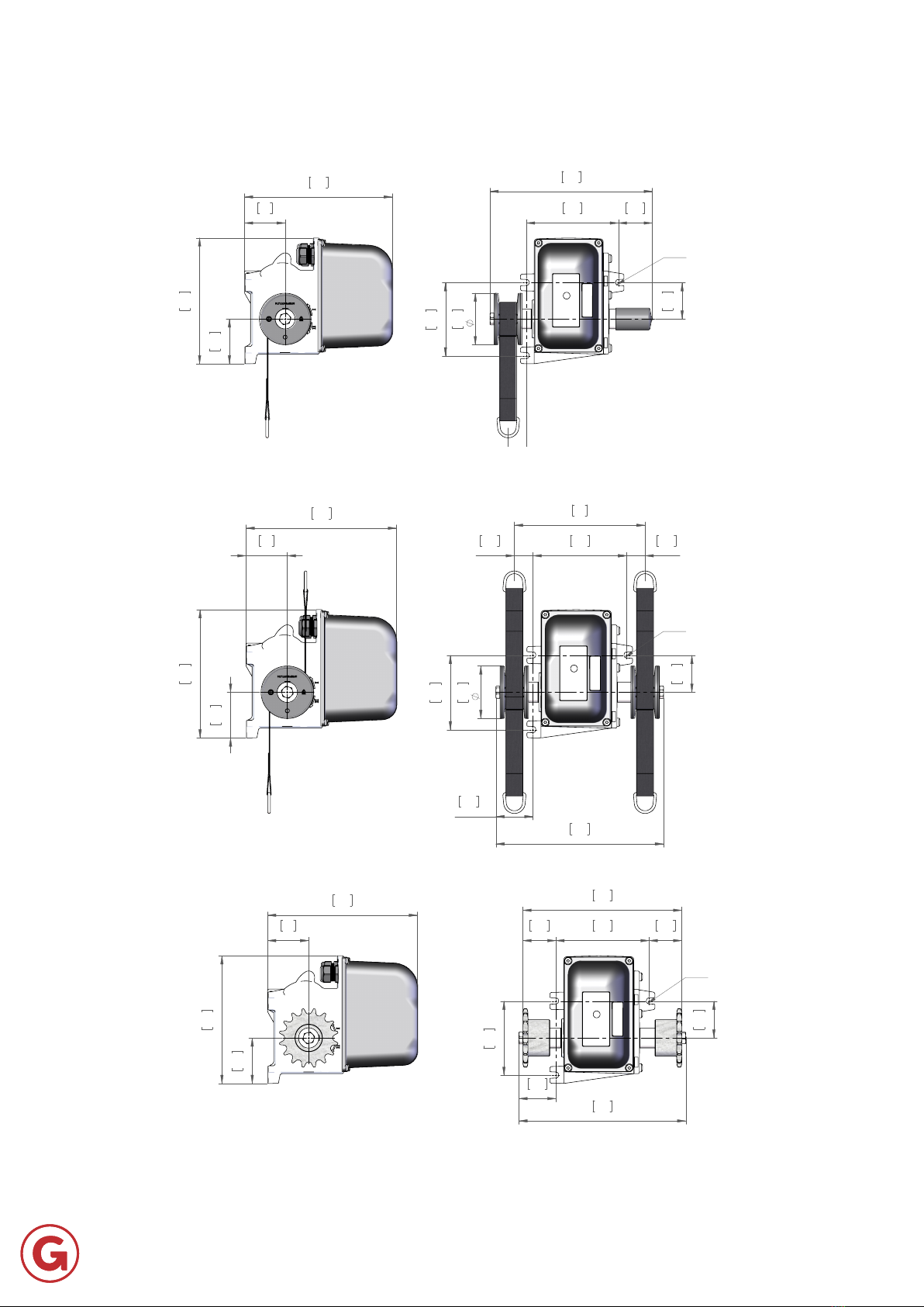
2.66
68
2.4
61
8.76
222
7.46
190
3.05
78
2.15
55
4.33
110
5.45
139
9.76
248
1.08
28
1.06
27
7.6
193
2.16
55
3x M8
2.66
68
2.4
61
8.76
222
7.46
190
2.15
55
4.33
110
5.45
139
9.76
248
2.16
55
1.93
49
1.91
49
9.29
236
3x M8
2.66
68
2.4
61
8.76
222
7.46
190
3.05
78
2.15
55
4.33
110
2.02
51
5.45
139
9.63
245
1.08
28
3x M8
Dimensions

5
Technical specications
Metric. | Imperial
Maximum output torque Nm | lbf-ft 90 | 66.38
Single winch drum maximum pulling force in reduced power kg | lbs
Double winch drum maximum pulling force in reduced
power (per belt)
kg | lbs
Winch drum diameter
Roll-up speed
Standard speed (½ speed setting via DIP switch) rpm 0,8 (0,4)
revs.
Supply voltage 24 (± 10%)
Power consumption VA 72
Power consumption in reduced power-mode (limited output
torque)
VA 48
Maximum current A 3
Maximum current in reduced power-mode (limited output
torque)
A 2
Protection - Thermal overload 3A
Digital control: bus type -
Analog control: signal (galvanically isolated)
> 2
Action of operating @ signal failure - To pre-set opening position
Weight kg | lbs
-
Housing material -
Ambient temperature
IP rating protection class -
6
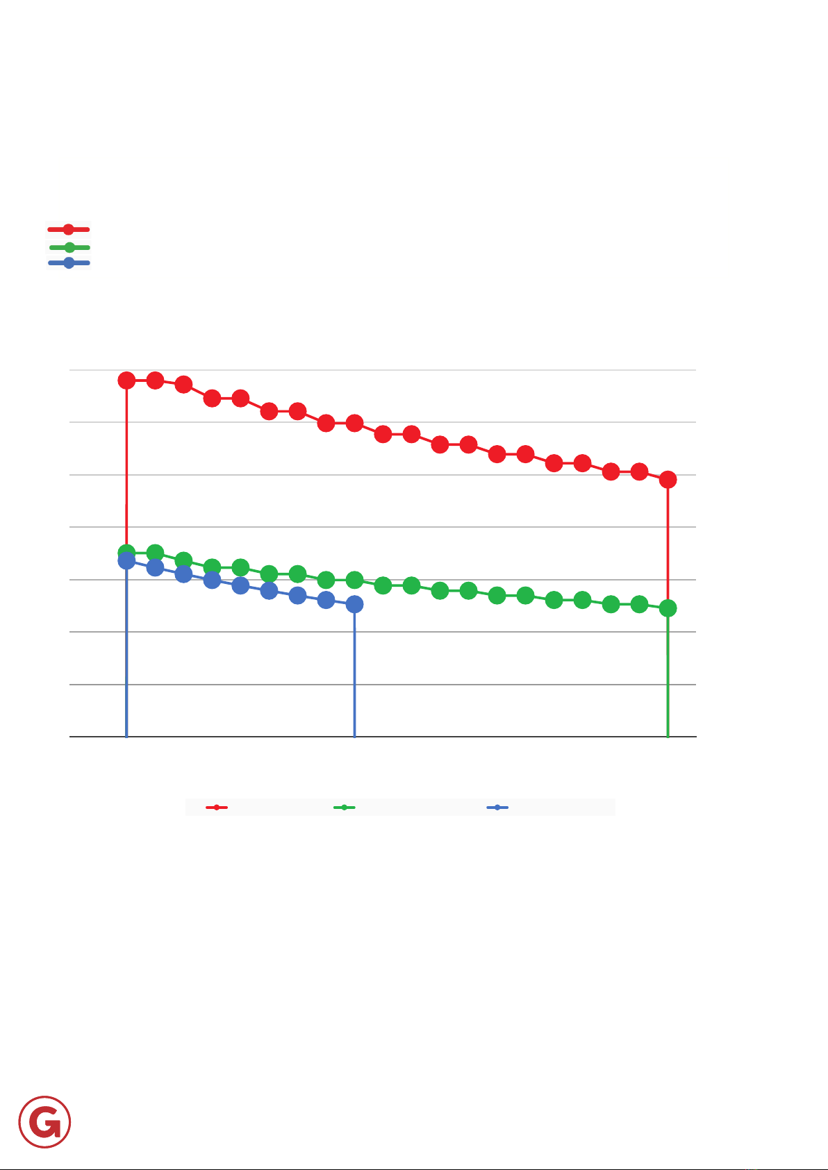
Technical specications
The graphs below shows you the pulling force in relation to the length of the winch belt.
The graph lines show the following:
Displays the graph line of the drum with 1 winch belt [kg]
Displays the graph line of 2 drums with 1 winch belt each [kg]
Displays the graph line of 1 drum with 2 winch belts [kg]
340 340 336
323 323
311 311
299 299
289 289
279 279
270 270
261 261
253 253 245
175 175 168 161 161 155 155 150 150 144 144 139 139 135 135 130 130 126 126 123
168 161 155 150 144 139 135 130 126
0 100 200 300 400 500 600 700 800 900 1000 1100 1200 1300 1400 1500 1600 1700 1800 1900 2000 2100 2200
Pull force per winch belt
[kg]
Winding length winch belt
[mm]
Pulling force vs Winch belt lenght
[metric]
1 drum with 1 belt [kg] 2 drums, both with 1 belt [kg] 1 drum with 2 belts [kg]

7
Technical specications
The graphs below shows you the pulling force in relation to the length of the winch belt.
The graph lines show the following:
Displays the graph line of the drum with 1 winch belt [lbs]
Displays the graph line of 2 drums with 1 winch belt each [lbs]
Displays the graph line of 1 drum with 2 winch belts [lbs]
750 750 741
712 712
685 685
660 660
636 636
615 615
594 594
575 575 558 558 541
386 386 370 356 356 342 342 330 330 318 318 307 307 297 297 288 288 279 279 270
370 356 342 330 318 307 297 288 279
0 4 8 12 16 20 24 28 32 36 40 44 48 52 56 60 64 68 72 76 80 84
88
Pull force per winch belt
[lbs]
Winding length winch belt
[inch]
Pulling force vs Winch belt lenght
[imperial]
1 drum with 1 belt [lbs] 2 drums, both with 1 belt [lbs] 1 drum with 2 belts [lbs]

8
Important procedures are emphasised in this user manual in a separate box with the initial lines printed in bold. See
below for an explanation of the various instructions you will encounter in this manual.
Symbol Meaning Unit Metric | Imperial Symbol Meaning Unit Metric | Imperial
T Torque Nm | lbf-ft n Rotational speed rpm
P Power kW | hp L Length mm | inch
U Voltage m Mass kg | lbs
I A v Roll-up speed i
Tip - -
Note - Electrical -
Instruction Explanation
Tip
more practically.
Attention! Remarks with supplementary information for the user. These remarks draw the user’s
attention to potential problems.
Material damage can occur when the procedures are not followed carefully.
Warning!
procedures are not followed carefully.
Risk of injury or death! The user’s life is directly endangered.
Explanation of symbols on the motor gearbox
The following symbols are shown on the motor gearbox
Symbol Meaning Symbol Meaning
No pressure cleaning Read the documentation
Electrically live parts PE connection (earth)
1 Explanation of symbols and safety instructions

9
1 Explanation of symbols and safety instructions
Installation
• Read this installation manual carefully and in full.
•
• Strictly observe the step-by-step procedures set out in the installation manual.
•
maintenance and servicing.
•
material damage due to the high torque of the motor gearbox.
General safety instructions
• With attached or driven components there is a risk of becoming trapped or injured. Amongst other things, the safety
devices or a dead-man vigilance system.
• Do not allow people to stand under or close to suspended loads.
• Attached or driven parts may have a shorter service life than the motor gearbox itself.
•
conditions. We strongly recommend that for hoisting applications you use a motor gearbox equipped with a
mechanical brake and mount a fall-arrest brake on the drive shaft.
• Never loosen screws, couplings or other parts while the drive train is loaded externally.
• Also observe national legislation and guidelines regarding working conditions and safety.
• .
• Despite careful planning and compliance with all regulations, some risks cannot be prevented.
Qualied sta
-
plant or system is always required before work may be carried out.

10
determine all necessary positions. A brushless motor operates according to the step motor principle: if the next position
is not reached, an alarm relay will be activated.
Manufacturer
The address details of De Gier are set out below:
De Gier B.V.
Westlandseweg 9
NL-2291 PG Wateringen
The Netherlands
I : www.degierdrivesystems.com
T : +31 174 – 292 089
Identication plate
Article number
The structure of the article number on the above rating plate is set out below with an explanation of the possible
versions.
CODE SERIES Force
[kg]
Force
[lbs]
Version Voltage
[VDC]
Speed @ 50Hz
[ x 0,1 rpm]
Accessories
P 300 661 1 24 8 L
Possible series
Materials and parts of the gearbox
Gearbox part Materials
Gear wheels, shafts, bearings, retaining rings, … Steel
Gear unit housing, housing parts Aluminium
Worm gears
Shaft seals, sealing caps Elastomer (with steel)
Gaskets Paper based and plastic elastomer
Limit switch and protective cover Plastic
Gear oil Enriched mineral oil
Electronics Various
2 Product
1
2
3
4
6
7
Article number
Production date
Serial number
De Gier barcode
Table of contents
Popular Winch manuals by other brands


Topex
Topex 97X080 Instructions for use

Eastbound
Eastbound MotoWinch 1707001 operating instructions

Runva
Runva EWD8000 Assembly & operating instructions

Ingersoll-Rand
Ingersoll-Rand LIFTSTAR FG 1500/CN Series Parts, operation and maintenance manual

Granit
Granit 11157675 operating instructions

TREX
TREX TB75 user manual