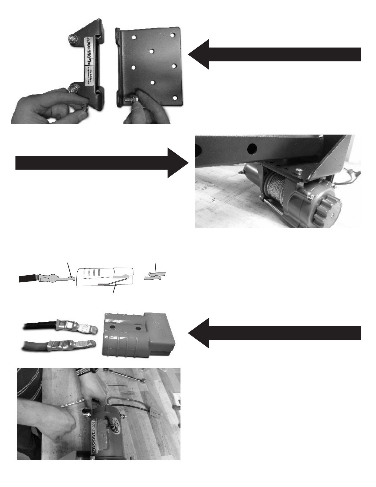
American Landmaster 17153 User manual

800-643-7332 • AmericanLandMaster.com 2500 lb. CAPACITY WINCH KIT – 17153 (full size) / 17530 (crew cab)
SPECIAL REQUIREMENTS: Requires the use of a front receiver hitch
and auxiliary accessory distribution block.
TOOLS REQUIRED
Pliers Needle Nose pliers
phillips screw driver 1/2 wrench or socket (2)
5/16 wrench or socket wire crimper
wire cutter/stripper 13mm wrench or socket (2)
9/16 wrench or socket (2) 5/32 allen key
10mm wrench or socket (2)
ESTIMATED INSTALLATION TIME
PARTS LIST FOR AMERICAN LANDMASTER INSTALLATION (parts not shown actual size)
RECOMMENDED SKILL LEVEL
60 - 90 minutes Intermediate
Before you begin, check the contents of the kit against the parts list below. Immediately contact American LandMaster with any questions or discrepancies.
American LandMaster cannot assume responsibility for any damage or injury resulting from incorrectly installed parts.
American LandMaster suggests that accessory kits be installed by an authorized American LandMaster dealer or service center.
15961 Rev. C
page 1 of 7
(4) M8 x 1.25 x 20 bolt
(4) M8 slit lock washer
(4) M8 flat washer
(4) M8 x 1.25 x 35 bolt
(4) M8 slit lock washer
(4) M8 flat washer
(4) M8 x 1.25 nylon
insert lock nut
(2) M8 x 1.25 x 20 bolt
(2) M8 slit lock washer
(2) M8 flat washer
(2) M8 x 1.25 nylon
insert lock nut
hand held controller
rubber boots
dash mount
controller hardware
guide roller
mounting plate
relay / hardware
receiver pin clip
quick connect terminals
quick connectors
winch mount
clevis pin
winch
dash mount controller
relay to winch wires
winch hardware (listed above)
battery to relay wires
snatch block roller fairlead
winch hook
grab strap

15961 Rev. C
page 2 of 7
STEP 1 INSTALL ROLLER FAIRLEAD
STEP 3 MAKE QUICK CONNECTS
STEP 2 WINCH ON WINCH PLATE
Install the roller fairlead to the mounting plate using two M8x20 cap
screws, flat washers, lock washers and hex nuts.
Locate the 4 foot red and black cables from your installation kit.
Using a wire cutter, cut both cables 1 foot from one end of each cable.
You will now have two 3-foot cables with a ring terminal on one end,
and two 1-foot cables with a ring terminal on one end. These cables
will be your quick disconnect. Strip all four bare wire ends and crimp
the quick connect terminals onto each wire. Install the wire with
terminal into the plastic quick connector housing, paying special
attention to ensure that the black wires are on the (-) side and the red
wires on the (+) of each connector housing. Connect the ring terminal
end of the short wires to the winch motor terminals, black on (-), red
on (+). Set the winch aside for now.
Place the winch upside down on a flat surface and align the holes in
the mounting with plate with the holes in the bottom of the winch.
Carefully place the winch mount on top of the mounting plate to en-
sure your bolt holes remain aligned. Bolt the mount, mounting plate,
and winch together using the M8x15 cap screws and lock washers.
These bolts thread directly into the bottom of the winch. Tighten these
bolts securely, but do not overtighten.
Quick Connect Terminal Quick Connector
Metal Tab
Properly Connected
Quick Connect Terminals
crimped onto wire side view
locks quick connect terminal in place

STEP 4 REMOVE HOOD
Remove the hood by removing the four bolts (one on either side above
front tire, and two on either side of hood logo) using 1/2 socket and
wrench.
STEP 6 REMOVE CONSOLE
STEP 5 REMOVE PROP SHAFT COVER
Remove the center console cover by using a pry tool or screw driver,
then remove the console using a 5/16 socket.
If 4WD (if not, skip to step 3) use a 1/2 socket and wrench to remove
the prop shaft cover.
If your unit is a crew, at this time use the same tools to remove the
rear seat console.
1/2” bolt
center console cover
15961 Rev. C
page 3 of 7
carefully pry here

STEP 7 REMOVE SEAT AND SEAT TRAY
Remove the seat cushion by lifting the rear of the seat, pivoting the
seat on the front of the seat surround. Once the seat is in the vertical
position, lift it clear of the surround. With the seat removed, you may
now lift the front edge of the under-seat tray, and removing it.
STEP 9 AUX BLOCK AND / OR FRONT RECEIVER
STEP 8 DISCONNECT BATTERY
If not already equipped, install the auxiliary distribution block at this
time. Follow the instructions included in kit 17233. Additionally, if the
unit is not already equipped with the required front receiver, install
that now following the instructions included in that kit.
Disconnect the battery wires using a 7/16 wrench and socket.
15961 Rev. C
page 4 of 7
positive
negative
front of vehicle
48V UNIT BATTERY DISCONNECTION

STEP 10 MOUNT RELAY TO AUX BLOCK PLATE
Using the supplied screws, mount the winch relay to the auxiliary
accessory block in the specified location. Tighten mounting screws.
STEP 12 CONNECT QUICK CONNECT TO RELAY
STEP 11 POWER THE RELAY
Connect the ring terminal ends of the 3-foot quick connect cable to
the relay terminal. Connect the red cable to ‘motor (+)’ and the black
cable to ‘motor (-).’ Secure the cables to the frame tubes with zip ties
as you route the quick connect to the front of the vehicle, placing the
quick connect in a location easy to access from the front of the unit.
Attach the 6-foot battery cables (10-foot for Crew units) to the relay
terminals. Connect the red cable to ‘battery (+)’ and the black wire to
‘battery (-).’ Route the cables down through the console of the unit and
through to the battery. Connect the red wire to the (+) and the black to
(-). Secure the cables to the console support on the driver’s side of the
console to ensure the cables cannot become entangled in the prop shaft
(4WD units). Any excess cable should be coiled up and zip tied in the dash
compartment.
FOR USE ON 48V UNITS: Connect negative wire to circled negative
connection shown, and hook the positive up to the positive connection
shown. MUST be hooked up to 3 batteries in series. Each battery is
8 volts - three in series will provide the winch with 24 volts and allow it to
operate correctly.
15961 Rev. C
page 5 of 7
auxiliary accessory distribution block plate
mount here
auxiliary accessory
distribution block
auxiliary accessory
distribution block
to battery positive
to battery negative
to “motor (+)”
to “motor (-)”
positive
negative
front of vehicle
FOR USE ON 48V UNITS

STEP 13 CHOOSE / INSTALL WINCH CONTROLS
Your winch comes with two controller options. A switch that can be
mounted into the dash, or a handheld joystick style controller that be
operated from outside the unit. Choose your preferred controller style
of controller, install and connect to the relay.
Hand held Controller - Drill a hole through the back of your
glovebox that the is large enough for the 4-pin connector to be
threaded through. Run the connector through and attach to the relay.
The joystick can be stored in the glovebox when not in use.
Dash Mount Controller - Use template 1 at left to cut the switch
location out in the dash. The recommended location is shown at
left. To install, the switch must be disassembled and the back of the
switch waterproofed with electrical tape.
STEP 15 INSTALL HOOK AND STRAP
STEP 14 INSTALL WINCH INTO RECEIVER
Use needle nose pliers to remove the cotter pin from the clevis on
the winch hook, and remove the pin from the hook. Ensure the clutch
control knob on the winch is in the ON position, and remove the
rubber band from the spool, being sure to keep tension on the spool
to prevent cable from unraveling from the spool. Carefully turn the
control knob to OFF position and feed just enough cable through the
fairlead to attached the hook. Immediately return the winch control
knob to the ON position, keeping tension on the cable to prevent
unspooling. Install the clevis pin through the hook and cable loop, and
re-install the cotter pin. Use your controller to reel the cable back in
and tight on the winch.
Re-install the seat tray, seat, console, prop shaft cover, and hood.
Install the winch into the receiver and plug in the quick connection.
Use your controller to verify that the motor engages before
progressing with the installation.
15961 Rev. C
page 6 of 7
dash mount controller location
dash mount controllerhand held controller
dash mount switch waterproofed with electrical tape
template 1

Fig. 7
Fig. 9
• Briefly operate the controller that is being used (stationary or handheld) to ensure that
the winch works properly.
• IN - button should retract the winch cable
• OUT - button should extend the winch cable
• If operation is reversed, the power connections to the winch may be connected
backwards. Correct the wiring before continuing with operation.
• Standing aside the vehicle, retract the winch cable and winch the item as desired.
Winch cable may slip or break causing serious injury
or death
WARNING
Do not retract the hook all the way back into the winch
roller guides as this will damage the roller and could
lodge the hook in the winch
CAUTION
Overwinding the winch cable into the roller guides can
jam the winch causing it to not release with the
twist knob.
CAUTION
Constant duty loading of the winch will overheat the
winch motor and may cause damage to both the winch
and the battery.
CAUTION
Fig. 8
Additional Winch Information
• When finished pulling the load, secure the load and add slack to the wire cable by
reversing the direction which will release tension and allow easy disconnection from
the hook.
• Duty Cycle: 5% - This winch is designed for intermittent use. The duty cycle is the
amount of time the winch can operate at its maximum capacity for a 15 minute period
of time.
• 45 Seconds at max rated load
• 14 minute rest between winching at rated load
• Double line rigging can be utilized to reduce the winch load. An appropriate pulley
block is included for this technique.
• Wear ANSI approved safety gear including gloves, goggles and shoes.
• Entanglement may occur. Do not wear loose clothing or jewelry, as they may get
caught in moving parts. Restrain long hair.
• Do not lift items vertically.
• Do not use to lift or move people.
• Do not use vehicle to pull on the winch cable and assist the winch.
• Disconnect battery cables before working on or near the winch cable, drum, roller
guides, or wire connections to prevent accidental starting.
• Inspect the winch before each use. Cracks, bent parts, frayed or kinked winch cable
will weaken the integrity of the winch and may cause sudden failure. A winch with
damaged components or questionable winch cable must not be used.
• Do not exceed the rated load capacity of the winch.
• Be aware of dynamic loading! Sudden load movement may briefly create excess load
causing product failure.
• Do not release the clutch under load.
• Do not place fingers through the hook. Fingers may get caught and entangled in
winch roller guide. Use supplied strap to hold hook.
• Stay clear of the winch cable when under load. Standing in the direct line of the
winch cable or behind the winch while operating may cause serious injury or death if
the winch cable were to break or slip.
• Do not use a recovery strap to winch. Recovery straps are designed to stretch and
may suddenly break and spring back towards the operator.
• Secure the load after moving. This winch is not equipped with a locking
mechanism.
• Keep at least 5 full turns of winch cable on the drum. Connection to the drum is not
intended to sustain a full load.
• People with pacemakers should consult their doctor or physician before use.
Electromagnetic fields in close proximity to heart pacemaker could cause
pacemaker interference or pacemaker failure.
WARNING THE FOLLOWING MAY CAUSE SERIOUS INJURY OR DEATH!
Contact American LandMaster Customer Service for questions
or problems that may arise with the assembly and starting of
this unit at 800-643-7332 or at americanlandmaster.com.
Fig. 6
Check your vehicle:
• Examine the winch cable. Do not use the winch if the cable is frayed, kinked or
damaged.
• Check the Winch electrical connections to ensure that they are tight and clean.
• Put the vehicle transmission in NEUTRAL and apply the parking brake.
Prepare the Winch:
• IF the vehicle with the winch is to
remain in place during the winch
operation, engage the parking brake and
chock the wheels (chocks sold
separately).
• Use the hook strap to pull out the
wire cable by moving the Clutch Control
Knob to the “OFF” (Free Spool) position
as shown in see figure 6.
Leave at least 5 full turns of wire cable on the drum.
WARNING
Do not wrap the winch cable around the object and hook
onto the cable itself. This will damage the winch
cable and object being pulled (see figure 7).
CAUTION
Basic Operation
FREE SPOOL
ENGAGE
“OFF” position
“ON” position
Attach Winch to the Object:
• Attach to the object by using a pulling point, tow strap or chain.
• Attachment point must be centered in the loop of hook and the safety clasp must be
fully closed (see figure 8).
• DO NOT use a recovery strap while winching. They are designed to stretch and
can suddenly whip back towards the operator during a winching operation.
• Place a rug or carpet over the winch cable span (approx. 6’ from the hook) to help
absorb the force released if the cable breaks (see figure 9).
• Move the Clutch Control Knob to the “Engaged” position and use either the stationary or
handheld controller to operate the winch.
15961 Rev. C
page 7 of 7
This manual suits for next models
1
Table of contents
Other American Landmaster Winch manuals
Popular Winch manuals by other brands

Farmi Forest Corporation
Farmi Forest Corporation JL 351P OPERATION, MAINTENANCE AND SPARE PARTS MANUAL

Mile Marker
Mile Marker SEC8 ES Installation and operator's manual

Warn Industries
Warn Industries 9-C-48 Series manual

HADEF
HADEF 42/87P Installation, operating, & maintenance instructions

Warn
Warn 70924 installation instructions

POWERWINCH
POWERWINCH RC23 owner's manual