DEGREE CONTROLS ROOSTER PRESSURE 100 User manual

Rooster™ Pressure100 USER MANUAL 62314MN000-A00
1 of 30
High Performance Air Pressure
Sensor
with Full-Color Touch Screen Display
Version 1.01
Complete Kit includes:
oSensor Display Module
oPressure Sensor
oPower Supply (optional)
oDoor Switch (optional)
This is proprietary information of Degree Controls Inc., contents are protected under US copyright laws ©
Degree Controls, Inc. 2020.

Rooster™ Pressure100 USER MANUAL 62314MN000-A00
2 of 30
Contents
Product Overview..................................................................................................................................................4
Contents ....................................................................................................................................................................4
Hard Button Overview ...............................................................................................................................................5
Soft Buttons and Home Screen Layout ......................................................................................................................6
Rear Panel Layout for Advanced Connections...........................................................................................................9
Technical Specifications.......................................................................................................................................10
Connection and Wiring Information ....................................................................................................................10
Door Switch Input....................................................................................................................................................11
Unoccupied Room Input ..........................................................................................................................................11
Alarm Output...........................................................................................................................................................11
Mechanical Information ...................................................................................................................................... 12
Display Module Mechanical Drawing......................................................................................................................12
Pressure Sensor Mechanical Drawing .....................................................................................................................12
Template for Pressure Sensor Mounting .................................................................................................................13
External Face Plate Mechanical Drawing ................................................................................................................13
Installation .......................................................................................................................................................... 14
Installation Overview...............................................................................................................................................14
Back Plate Mounting - Display Module ...................................................................................................................15
Installation Example................................................................................................................................................15
Boot Up Procedure .............................................................................................................................................. 19
Access Tier Privileges: USER, EH&S & CERTIFIER .................................................................................................. 20
Set/Change Passwords ........................................................................................................................................20
Calibration...........................................................................................................................................................20
Thresholds ........................................................................................................................................................... 21
Occupied and Unoccupied Thresholds.....................................................................................................................21
Adjust Occupied and Unoccupied Thresholds..........................................................................................................21
Alarms/Sound......................................................................................................................................................22
Alarm Controls.........................................................................................................................................................22
Brightness............................................................................................................................................................ 25
Pressure Resolution............................................................................................................................................. 25

Rooster™ Pressure100 USER MANUAL 62314MN000-A00
3 of 30
I/O Polarity..........................................................................................................................................................26
Data Logging........................................................................................................................................................26
Troubleshooting ..................................................................................................................................................27
Alarm Troubleshooting............................................................................................................................................27
General Troubleshooting.........................................................................................................................................27
USB Field Upgrade Procedure .............................................................................................................................. 28
Factory Reset Procedure...................................................................................................................................... 28
GUI Map ..............................................................................................................................................................29
Warranty ............................................................................................................................................................. 30

Rooster™ Pressure100 USER MANUAL 62314MN000-A00
4 of 30
Product Overview
Congratulations on your purchase of the RoosterTM Pressure100, the next-generation air
pressure sensor and alarm for critical pharmaceutical and clean room applications where
constant positive or negative air pressure differential is required to be viewed, monitored,
alarmed, and even communicated to building and laboratory systems.
Degree Controls Inc. designed the RoosterTM Pressure100 to meet the demand for high
performance room pressure sensing applications with an intuitive, glove-friendly, color
touchscreen interface and best-in-class pressure and humidity sensing module. The
instrumentation class sensors inside require no ongoing factory recalibrations, merely an annual
recertification process. The RoosterTM Pressure100 comes calibrated and with a certificate of
conformance.
The RoosterTM Pressure100 uses a bright, backlit display and contains many simple-to-use
features and configuration capabilities built into an intuitive user interface that requires little to
no training to learn. Password-protected access tiers ensure greater safety in a range of
environments by limiting access to critical functions and system settings for specific, authorized
users.
The RoosterTM Pressure100 is the first pressure sensor with USB-based plug and play firmware
upgrades to keep your product current and operating to the latest standards. Register with us to
receive these product updates at http://www.degreec.com/en/support/register.html.
This manual will guide you through installation, firmware upgrades, alarm control settings, and
the full range of features for the RoosterTM Pressure100.
Contents
The RoosterTM Pressure100 consists of:
(1) Display Module
(1) Pressure Module, comprised of:
Pressure Sensor with connected Sensor
Cable, length is 2m [6.6’]
External Face Plate
Flexible Tubing, length is 610 mm [2’]
(1) Power Cable
(4) Sheetrock Anchors
(4) Screws-Phillips Flat Head #6x1”Wood Screw (For
mounting Pressure Sensor & External Face Plate)
(2) Screws–Phillips Flat Head 6-32x1”Machine Screw
(For mounting Display Module Back Plate)
(1) Template for Pressure Sensor Mounting
as well as your power selection and door switch kit option. Available Power Selections are:
Customer Supplied Power with Semi-Flush Mount Back Plate
US Power Supply with Wall Mount Back Plate
European Power Supply with Wall Mount Back Plate
Specify “Included” at time of order to have the optional Door Switch Kit included.
Figure 1 RoosterTM Pressure100 Contents

Rooster™ Pressure100 USER MANUAL 62314MN000-A00
5 of 30
Figure 2 Pressure Module, Cover Removed
Figure 3 External Face Plate with Removable Cover
Hard Button Overview
MUTE
Mutes the audible alarm, any time it is sounding. When the alarm
has been muted, a mute icon [ ] will appear in the top center
portion of the home screen. Just like a snooze button, the
audible alarm will re-sound, when the configurable time-out is
reached if ringback has been enabled.
HOME
Returns the user to the home screen when pushed from any
menu or info screen. * Cannot be used to abort some critical
system functions. *
LED
This red LED will flash while a pressure alarm is active. If the
room is in an Unoccupied state, the alarm will be muted by
default and the LED will flash during a pressure alarm. In all other
cases, this LED will remain off.
Cover
Base
Cover
Base

Rooster™ Pressure100 USER MANUAL 62314MN000-A00
6 of 30
Soft Buttons and Home Screen Layout
PRESSURE MODE
The pressure mode is displayed above the pressure reading on the home screen, Negative
Room, Positive Room.
>Home
TOGGLE AIR PRESSURE UNIT TYPE
Instantly toggle displayed pressure units between Pascals, inches of water, or centimeters of
water by pressing on the displayed room differential pressure reading on the home screen.
>Home
TOGGLE TEMPERATURE UNIT TYPE
Instantly toggle displayed temperature units from Fahrenheit to Celsius or vice versa by
pressing on the displayed temperature reading on the home screen.
>Home
ON-SCREEN ALERT BANNERS
A yellow banner will appear beneath on-screen pressure readings to alert users of the
following scenarios: 1) Uncalibrated Sensor 2) Sensor Module Failure 3) Low/High Room
Pressure. Alarm latched status will also display here.
>Home
USB INTERFACE FOR FIELD UPGRADE PROCEDURE
Firmware upgrades can be installed on-site via USB flash drive.
CUSTOMIZABLE BOOT SCREEN
Our engineers can configure your unit with a custom image or logo file (240x320) in portable
network graphic (.png) format to display on bootup. Contact our sales team to get started:
Room Name
Air Pressure
(touch to toggle units)
% Relative Humidity
Air Temperature
(touch to toggle units)
Settings Menu
USB input for keyboard
and firmware upgrades
Time of Day
Alert Banner
Quick access to current
configuration settings including
alarm thresholds, calibration date,
and firmware version
Status Color (Green, Yellow or Red)
Unoccupied Room/Mute Indicator
Data Logging Indicator (Green Dot)
Pressure Mode

Rooster™ Pressure100 USER MANUAL 62314MN000-A00
7 of 30
ALARM VOLUME
Users can toggle through low, medium or high alarm volumes. If logged in as an EH&S or
Certifier, a global minimum volume threshold can be set. This restricts a standard user from
setting an alarm volume too low for a facility’s safety requirements.
Home> Settings>System>Alarms/Sound>Device Volume
KEYPAD SOUNDS
Users may toggle keypad beep sounds on and off.
Home> Settings>System>Alarms/Sound>Key Beep
ALARM LATCHING
EH&S or Certifier users can set up latched alarms to indicate that a low or high pressure state
has occurred in the “Alarms/Sound
Alarm Controls” menu. Optionally, a password can be required to clear any latched alarms.
Users must then enter EH&S or Certifier passcode to unlatch an alarm.
Home> Settings>System>Alarms/Sound>Alarm Controls>Latch Alarm
ALARM RINGBACK
EH&S or Certifier users can configure the amount of snooze time before an alarm rings again
after being muted in the “Alarms/Sound
Alarm Controls” menu.
Home>Settings>System>Alarms/Sound>Alarm Controls>Alarm Delay Settings>Ringback
BACKLIGHT DIMMING
Users can toggle the brightness setting, as well as the brightness of the screen when set to
“dim”. A “time before dim” option is available that sets the screen to dim after a
predetermined amount of time has expired.
Home> Settings>System>Brightness
PRESSURE RESOLUTION
EH&S or Certifier users can select the resolution of air pressure units displayed in Pascals,
inches of water, or centimeters of water.
Home>Settings>System>Pressure Settings>Pressure Resolution
CLOCK
Users logged in as EH&S or Certifier can set time, date and change clock to display in 12 or 24
hour format.
Home> Settings>System>Time>Date and Time Settings
ADJUSTABLE I/O POLARITY
Users may connect a variety of dry contact relay devices, like wall switches or door sensors, to
indicate whether the room has been accessed in either an Occupied or Unoccupied state. The
way the Rooster Pressure100 interprets the trigger signals from these devices can be adjusted
by changing the I/O polarities from Normally Open or Normally Closed states.
Home> Settings>System>Advanced>I/O Polarity
CUSTOM ROOM NAME
Users logged in as EH&S can change the default “Room Name” to a custom name. This is
useful for naming the sensor in larger distributed systems, or to denote a company asset
number. The user may set a 12-digit numeric room name with the provided on-screen

Rooster™ Pressure100 USER MANUAL 62314MN000-A00
8 of 30
keypad OR plug in a USB interface keyboard to enter a 12 character alphanumeric tag.
Home> Settings>System>Advanced>Configure Room Name
PASSWORD-PROTECTED ACCESS TIERS: CERTIFIER & EH&S
Password protected access tiers enable advanced configuration options and features.
Home> Settings>System>Advanced>Change Passwords
UNOCCUPIED ROOM THRESHOLD
EH&S or Certifier users can configure two convenient modes of operation, Occupied or
Unoccupied, each with their own threshold triggers. This is especially useful when users
desire to mute alarms and/or adjust thresholds when the room is unoccupied, typically for
night service conditions. For more information on setting thresholds, see thresholds section
of manual.
Home> Settings>Thresholds
DATA LOGGING
The RoosterTM Pressure100 features a data logging feature with the ability to export to .csv file
via USB drive. When data logging is active, a green dot will appear at the top of the screen
next to the clock. The default polling rate is 5 seconds, but this can be adjusted from 1
second up to 1 minute.
Home>Settings>System>Data Logging

Rooster™ Pressure100 USER MANUAL 62314MN000-A00
9 of 30
Rear Panel Layout for Advanced Connections
Figure 4 Connections
Connection
Description
Connector Type
Mating Connector
Power Entry
2-pin, polarized,
Phoenix Contact
Included with display module.
RS485
4-pin, push-in
spring connection
Included as part of pressure sensor.
For replacement, Part Number: Phoenix Contact 1778573
Output
Connection
8-pin, polarized,
Phoenix Contact
*2-position
connectors will fit
Not included.
8-position orderable Part Number: Phoenix Contact 1803633
2-position orderable Part Number: Phoenix Contact 1803578
Input
Connection
10-pin, polarized,
Phoenix Contact
*2-position
connectors will fit
Not included.
10-position orderable Part Number: Phoenix Contact 1803659
2-position orderable Part Number: Phoenix Contact 1803578
RJ-11
Connection
RJ-11
Not used.
Table 1 Connections - Rear Panel of Display Module
The Door Switch Kit Option is specified at time of order.

Rooster™ Pressure100 USER MANUAL 62314MN000-A00
10 of 30
Technical Specifications
Connection and Wiring Information
Degree Controls recommends 18-24 AWG wire be used for all wiring connections to the input
and output connectors. The Power Entry connection has been prepared for you, and merely
needs to be pulled through the electrical box knock-out and connected to the Power Entry
connection of the display module.
The supplied sensor cable is terminated both ends and ships connected to the pressure sensor.
It needs to be pulled through the electrical box knock-out and connected to the RS485
connection of the display module.
Note: This manual describes a typical installation where the display module mounts semi-flush to
a standard electrical box. Other installation scenarios are possible.
Alarm Module Size
3.2” x 5.3” x 1.3” (82mm x 135mm x 32mm)
LCD Display Area
2.25”x 2.73” (57mm x 69mm)
Pressure Sensor Size
3.0”x 1.8” (77mm x 46mm)
External Face Plate Size
3.0”x 1.2” (77mm x 31mm)
Differential Pressure Sensing Range
-125 to +125 Pa (-0.5 to +0.5 in H2O)
Air Pressure Accuracy
3% of reading + 0.08 Pa (0.00032 in H2O)
Air Pressure Repeatability
0.5% of reading + 0.04 Pa (0.00016 in H2O)
Response Time
< 1 second
Supply Voltage –Display Module
24 VAC/VDC
Door Switch Input
Dry Contact Closure
Unoccupied Room Input
Dry Contact Closure (0V)
Relay Output
Qty. (1), 1A, 24VDC [Pin 1-2 Differential Pressure Alarm]
Optional Power Adapter
90-250V
Red LED indicator
160° viewing angle
Alarm Volume
0 - 85dB (adjustable)
Operating Relative Humidity
(non-condensing) 5 - 95%
Humidity Sensing Range
0-100% RH; accuracy ±2% at 0-80% RH, ±3% at 100% RH
Operating Temperature
40°F - 140°F (5°C - 60°C)
Storage temperature
-40°F - 185°F (-40°C - 85°C)
Product Weight
1 lb (454g)
Total Packaged Weight
1.5 lbs (680g)
Compliance Standards
RoHS

Rooster™ Pressure100 USER MANUAL 62314MN000-A00
11 of 30
The I/O connectors present on the RoosterTM Pressure100 have some pins deactivated as these
are reserved for future RoosterTM models designed for more advanced control functionality.
Leave these pins non-connected.
Door Switch Input
This door switch input is a digital input, dry contact, and the default I/O polarity of this door
switch input is normally closed. The design intent is that the door switch input be used in
combination with an external sensor to detect whether a door is open or closed:
Switch open means door open, and
switch closed means door closed.
Door switch input logic may be reversed using the I/O Polarity menu on the Rooster™
Pressure100 to achieve a different result.
DegreeC can provide you with an optional Door Switch Kit comprised of (1) dry contact sensor
with screw terminals and (1) 10-position connector which mates to the input connection of the
display module. For this dry contact sensor, the cable length from door switch to display
module can be 30m [100’] or more. If multiple door switches are being used, they should be
wired in series.
Note: Specify “Included” at time of order to have the optional Door Switch Kit included.
Unoccupied Room Input
The RoosterTM Pressure100 provides an additional digital input for room status, and default I/O
polarity of the unoccupied room input is normally open. The purpose of the Unoccupied room
input is to allow the user to use two different sets of alarm thresholds based on whether the
room is in an occupied or unoccupied state. Unoccupied room input logic may also be reversed
using the I/O Polarity menu on the Rooster™ Pressure100.
Once the wiring connections have been made, the user can assert the unoccupied room signal.
Three room profile alarm states can be selected:
Off (default): In this state, when the unoccupied room signal is asserted, the Pressure100
will ignore it.
Muted: In this state, when the unoccupied room signal is asserted, the Pressure100
triggers a muted alarm when pressure moves beyond Unoccupied Thresholds.
Unoccupied Thresholds are independently set.
Audible: In this state, when the unoccupied room signal is asserted, the Pressure100 will
audibly alarm when pressure moves beyond Unoccupied Thresholds.
Alarm Output
The RoosterTM Pressure100 alarms for differential pressure. The Alarm output is a relay output
and available on the output connection of the display module. I/O polarity logic of this output
may be reversed as well. See the I/O Polarity menu of the Rooster™ Pressure100.

Rooster™ Pressure100 USER MANUAL 62314MN000-A00
12 of 30
Mechanical Information
Display Module Mechanical Drawing
Figure 5 Display Module Mechanical Drawing
Pressure Sensor Mechanical Drawing
Figure 6 Pressure Sensor Dimensions
Rear Panel of Display Module

Rooster™ Pressure100 USER MANUAL 62314MN000-A00
13 of 30
Template for Pressure Sensor Mounting
Figure 7 Pressure Sensor Mounting Template Dimensions
External Face Plate Mechanical Drawing
Figure 8 External Face Plate Dimensions
Optional Pre Pilot Drill
Rooster™ Pressure100 USER MANUAL 62314MN000-A00
14 of 30
Installation
Installation Overview
Installation of the RoosterTM Pressure100 involves selecting and preparing an appropriate location,
wiring and connecting the unit, and then mounting the unit to the wall securely.
Notes:
Typically, the RoosterTM Pressure100 display module is mounted near an access door, at
eye level, and in the controlled room, with the pressure sensor mounted above it.
oIf you choose to mount the display panel in the reference space rather than the
controlled space, or choose some other mounting arrangement, the RoosterTM
Pressure100 will still work.
Customer supplied power with Semi-Flush mount back plate or included power supply
with Wall Mount back plate is specified at time of order. See Back Plate Mounting
section for more information.
It is recommended that the pressure module be located above the display module, and
within the same stud, for efficient wiring.
The pressure sensor should be mounted in an area free from drafts and turbulence.
The external face plate must be mounted opposite the pressure sensor in an adjacent
room or space.
You will need to connect the supplied flexible tubing between the pressure sensor and
the external face plate.
You will need to connect power, sensor and optional door switch & unoccupied room
input wires to the display module.
Be sure to leave enough room so that the display module’s USB port can be accessed.
Only qualified Facilities personnel should install the RoosterTM Pressure100.
Figure 9 Typical Installation for RoosterTM Pressure100
Pressure Sensor
Electrical Box
Display Module
CEILING
CONTROLLED SPACE
REFERENCE SPACE
External Face Plate
Sensor Cable
Tubing

Rooster™ Pressure100 USER MANUAL 62314MN000-A00
15 of 30
The Rooster Pressure100 is a pre-calibrated device, with stated accuracy performance. It
does not require any special certification process to function properly. However, this
should not imply that industry standard annual laboratory certification processes should
not be adhered to. This should be conducted at the end user discretion.
Back Plate Mounting - Display Module
The display module can be mounted using one of two back plate options:
Semi-Flush: The back plate sits partially inside a standard electrical box and is secured by self-
tapping screws. There is open back access to accept building power.
Wall Mount: The back plate sits directly on a wall or surface and is secured by self-tapping
screws or industrial Velcro. Sensor and control wiring access is at the back, while access for
power in from the wall mount power supply is at the bottom.
Figure 10 Semi-Flush Mount (left), Wall Mount (right) –for Display Module
Installation Example
The installation steps below represent a typical drywall installation with customer supplied power
and semi-flush mount back plate for display module.
Mounting Preparations
1. Determine mounting locations for the RoosterTM Pressure100 display module and
pressure sensor.
Display Module Mounting Preparation
2. Mark the wall for the electrical box where the RoosterTM Pressure100 display module will
be located, and make the cutout.

Rooster™ Pressure100 USER MANUAL 62314MN000-A00
16 of 30
a. The display module is designed to mount semi-flush where the back plate sits
partially inside a standard electrical box. Using this method, the display module
protrudes 15mm [0.6”] from the wall.
Figure 11 Semi-Flush Back Plate Mounting
Pressure Sensor Mounting Preparation
3. Using the enclosed template, mark the wall for pressure
sensor mounting. Take care to orient the template right
side up such that mounting holes are vertical.
4. Use a ¼” drill bit to drill holes for Tubing and Cable.
5. Install (2) drywall anchors.
External Face Plate Mounting Preparation
6. Use a ¾” drill bit to drill the center hole.
7. Drop the base of the external face plate (boss side) in the
hole, and mark the wall for face plate mounting.
Mounting holes should be horizontal.
8. Remove base from wall, and install (2) drywall anchors.
Pressure Sensor Connection and Mounting
The pressure module is comprised of a pressure sensor with connected sensor cable, external
face plate, and flexible tubing to connect the pressure sensor to the external face plate. The
pressure sensor and external plate are mounted on opposite sides of a wall which separates the
controlled environment from the outside, reference space. Inside the sensor are two pitons, one
of which is indicated with a red dot.
Electrical Box
Display Module Back Plate
Cable
Tubing
Mounting (2X)
Figure 12 Tubing & Cable Holes
¾” Drill
Mounting (2X)
Figure 13 Drop In Boss Side of
Base to Locate Mounting Holes

Rooster™ Pressure100 USER MANUAL 62314MN000-A00
17 of 30
The pressure sensor is typically mounted on the side of the wall with the display module.
9. Feed the flexible tubing through the pressure sensor base.
10. Connect the tubing to the appropriate piton on the pressure sensor. Be sure to leave
enough bend radius to ensure that the tubing will not kink, disrupting airflow.
Which piton you connect the tubing to depends on the environment in which the module is
placed:
If the external face plate is in a neutral pressure environment and the display module and
pressure sensor are in a pressurized environment (positive or negative), connect the
tubing to the piton not marked with the red dot.
If the display module and pressure sensor are in a neutral pressure environment and the
external face plate is inside a pressurized environment (positive or negative), connect the
tubing to the piton marked with the red dot.
11. Feed the tubing and sensor cable from the pressure sensor through the wall to the
external face plate and display module mounting locations respectively.
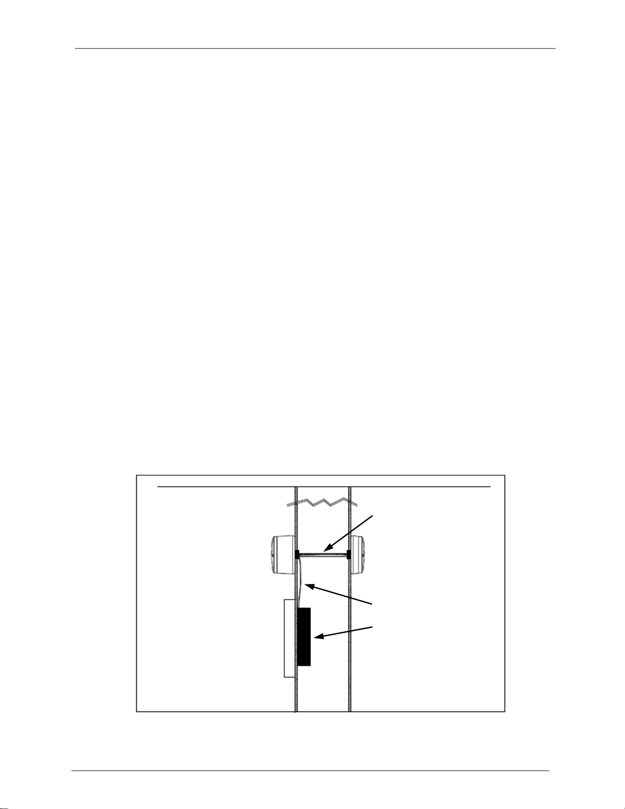
12. Run a bead of laboratory grade caulking, and fasten the pressure sensor securely to the
wall using the included screws.
13. Install cover: Align tabs, push cover onto base, and turn clockwise to lock in place.
Figure 14 Pressure Sensor Mounting
Display Module Connections and Mounting
14. Have a qualified electrician run 24 VAC/VDC to the prepared cutout, and connect to the
supplied power cable.
15. Punch out the appropriate knock-outs on the electrical box that will be secured to
drywall, route power and the sensor cable into the box, and install box to wall.
Note: Optional building management system or laboratory control system wiring should
be completed at this time.
Cover
Base
Screw (2X)
Cable
Tubing

Rooster™ Pressure100 USER MANUAL 62314MN000-A00
18 of 30
16. Secure the display module back plate using
the included screws.
17. Connect power and sensor to the display module.
Make any other optional connections to the
display module.
18. Align right side of display module with tabs on
back plate and snap display module in place.
External Face Plate Connection and Mounting
19. Connect the flexible tubing from the pressure sensor to the
base of the external face plate. You may trim the tubing to
length, but be sure to leave enough slack in the tubing to
prevent any kinks that may disrupt airflow.
20. Run a bead of laboratory grade caulking, and fasten the face plate to the wall using the
included screws.
21. Install cover: Align tabs, push cover onto base, and turn clockwise to lock in place.
Power
Cable
Sensor
Cable
Figure 15 Back Plate Secured to Electrical Box
Figure 16 Power & Sensor Connection
Figure 17 Tubing Connection

Rooster™ Pressure100 USER MANUAL 62314MN000-A00
19 of 30
Figure 18 External Face Plate Mounting
Boot Up Procedure
The RoosterTM Pressure100 does not have a power-on switch and will become
energized as soon as you apply power to it. The RoosterTM Pressure100 boots
to the screen depicted on the right, with a slot for a custom logo. The boot
screen is designed to support a custom image or logo file in portable network
graphic (.png) format with (240x320) dimensions. This feature must be
requested and is not setup for manual configuration.
Once the start procedure has completed, the Home screen will appear with
two system buttons and you will need to setup password-protected access
tiers for advanced system functions. This is explained in the “Access Tier
Privileges” section below.
You can reboot your RoosterTM Pressure100 at any time by pushing the hard “Home”and “Mute”
Buttons simultaneously until the Boot Screen reappears.
Tubing
Base
Cover
Screw (2X)

Rooster™ Pressure100 USER MANUAL 62314MN000-A00
20 of 30
ACCESS TIER PRIVILEGES: USER, EH&S & CERTIFIER
Users have the ability to customize their pressure areas within
a defined set of options for each authorization level. There
are three levels of access to the RoosterTM: User,
EH&S/Facility Manager and Certifier. These are managed by
logging in with a 4-digit numerical passcode. The User access
level does not require a passcode.
Access Privileges Defined
Function
Passcode Required
Adjust Alarm Volume
None
Alarm Latching Settings
EH&S, Certifier
Alarm Ringback Settings
EH&S, Certifier
Mute Live Alarm
None
Set Room Name
EH&S
Set Minimum Alarm Volume Threshold
EH&S, Certifier
Set Time / Clock Format
EH&S, Certifier
Toggle between Fahrenheit or Centigrade Temperature Units on Home
Screen
None
Toggle between Metric or Imperial Pressure Units on Home Screen
None
Toggle ON/OFF Keypad Sounds
None
Calibrate
Certifier
Unlatch Alarm
EH&S
Data Logging
EH&S, Certifier
SET/CHANGE PASSWORDS
To change or set a password, follow this GUI path to trigger the password change sequence:
Home>Settings>System>Advanced>Change Passwords
You will have to enter an EH&S or Certifier passcode to access the “Advanced” menu. To change
either the EH&S or Certifier passcode, you must first re-enter the old passcode. Please note that
if you are authorized to perform both EH&S and Certifier functions, you may set an identical
passcode for both access tiers to make logging in and accessing key functions easier.
Calibration
All RoosterTM Pressure100s are pre-calibrated before leaving the factory,
however we recommend a final recalibration when installation is complete.
Your local certifier should be recalibrating the unit on an annual basis, or
according to your laboratory directives. The calibration menu can be accessed
here:
Home>Settings>Calibration
Manufacturer default passcodes:
EH&S = 6823
Certifier = 1459
Table of contents
Other DEGREE CONTROLS Measuring Instrument manuals


