Rothenberger RO 458s User manual

1ENGLISH
RO 458s
rothenberger.com
MAN00148
RO 458s
EN Instructions for use

2ENGLISH
Contents Page
Table of contents UK
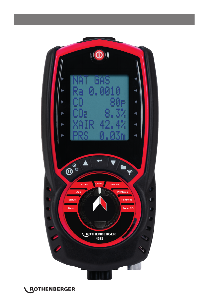
1 RO 458s Overview 4
2 Analyser Features and Keypad 6
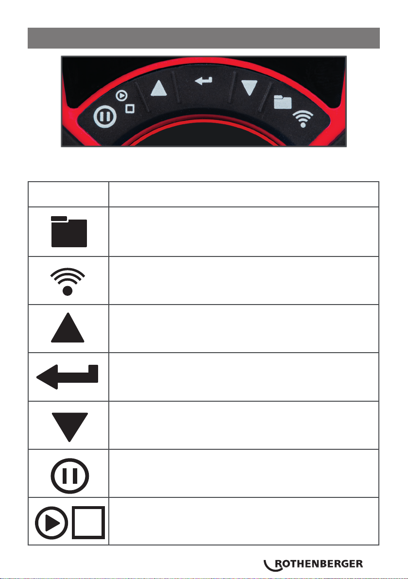
2.1 RO 458s Buttons 7
2.2 Analyser Layout 8
3 Batteries 10
3.1 Replacing batteries 10
3.2 Time & date 10
3.3 Charging NIMH batteries 10
3.4 Battery disposal 10
4 General Safety 11
4 Using your RO 458s for the first time 12
4.1 Using your RO 458s every time 12
4.2 Fresh air purge switch on 12
5 Using the menu 14
6 Measuring flue gasses 16
7 CO protection pump operation 17
8 Using your analyser 17
8.1 Combustion tests 17
8.2 Ratio display 18
8.3 O2/Eff display 18
9 Transferring results 19
8.4 AUX display 19
9.1 To view/print a logged report 19
9.2 Viewing/printing a logged combustion test 20
9.3 Kane infrared printer 20
9.4 Printouts 21
10 Commissioning test 22
11 Pressure & temperature testing 23
11.1 Pressure measurement good practice 24
11.2 Large bore tubing issues 24
1 RO 458S OVERVIEW..............................................4
2 ANALYSER FEATURES AND KEYPAD ....................6
2.1 RO 458S BUTTONS..........................................................7
2.2 ANALYSER LAYOUT ........................................................8
3 BATTERIES ...........................................................10
3.1 REPLACING BATTERIES .................................................10
3.2 TIME & DATE.................................................................10
3.3 CHARGING NIMH BATTERIES .......................................10
3.4 BATTERY DISPOSAL......................................................10
4 GENERAL SAFETY ...............................................11
5 USING YOUR RO 458S FOR THE FIRST TIME ......12
5.1 USING YOUR RO 458S EVERY TIME..............................12
5.2 FRESH AIR PURGE SWITCH ON ....................................12
6 USING THE MENU ...............................................14
7 MEASURING FLUE GASSES.................................16
8 CO PROTECTION PUMP OPERATION ..................17
9 USING YOUR ANALYSER.....................................17
9.1 COMBUSTION TESTS.....................................................17
9.2 RATIO DISPLAY.............................................................18
9.3 O2/EFF DISPLAY............................................................18
9.4 AUX DISPLAY ................................................................19
10 TRANSFERRING RESULTS ...................................19
10.1 TO VIEW/PRINT A LOGGED REPORT............................19
10.2 VIEWING/PRINTING A LOGGED COMBUSTION TEST .....20
10.3 KANE INFRARED PRINTER ............................................20
10.4 PRINTOUTS ...................................................................21
11 COMMISSIONING TEST .......................................22
12 PRESSURE & TEMPERATURE TESTING ................23
12.1 PRESSURE MEASUREMENT GOOD PRACTICE ..............24
12.2 LARGE BORE TUBING ISSUES.......................................24
13 LET-BY & TIGHTNESS TESTING ...........................25
14 ROOM CO TESTING .............................................27

ENGLISH 3
14.1 TEST TYPES....................................................................27
14.2 ROOM CO DISPLAY.......................................................28
15 USING YOUR RO 458S AS A THERMOMETER OR
PRESSURE METER .........................................................28
16 ANALYSER PROBLEM SOLVING .........................29
17 SPECIFICATIONS .................................................30
18 EU DECLARATION OF CONFORMITY.................32
19 COLD WEATHER PRECAUTIONS ........................33

4ENGLISH
Your RO 458s combustion analyser measures:
●Carbon Monoxide (CO)
●Carbon Dioxide (CO2)
●Oxygen (O2) if fitted
●Nitric Oxide (NO) if fitted
●Differential Pressure
●Differential temperature
Your RO 458s measures CO2 using KANE’s unique NDIR sensor.
Always use fresh outdoor air to “zero” your analyser during the initial
countdown or when prompted to “ZERO CO2” as indoor CO2 levels are
increased by human activity.
This applies even if your analyser measures O2 instead of CO2 as it is best
practice to use fresh, outdoor air during initial countdown to protect you
from unsafe levels of CO & CO2 possibly present in the room.
Depending on your options these parameters are calculated:
●Oxygen (O2)
●CO/CO2 ratio
● Carbon Monoxide (CO2)
●Combustion Efficiency
●Losses
●Excess Air
●Differential Temperature
Your analyser also measures CO levels in ambient air – useful when a CO
alarm is triggered – & performs a Room CO test for up to 30 minutes.
Your RO 458s has a structured Commissioning Test to help install boilers.
Your RO 458s has a protective rubber cover with magnets for
“hands-free” operation & is supplied with a flue probe with integral
temperature sensor.
Your analyser has a low flow detector to switch off the analyser’s pump if it
detects an over filled water trap.
1 RO 458s Overview

ENGLISH 5
Your RO 458s has a large 6 line display showing data & test results based on
your actions.
Your RO 458s can send test results to our optional KANE IRP-2
infrared printer or KANE’s wireless printer App.
The memory can store up to:
●60 combustion tests
●20 AUX tests
●20 let-by/tightness tests
●20 temperature & pressure tests
● 20 room CO tests
● 20 commissioning Tests
You can personalise 2 lines of 16 characters on your test results header - for
example your company name & telephone number.

6ENGLISH
2 Analyser Features and Keypad

ENGLISH 7
2.1 RO 458s Buttons
Function keys
ICON Description Icons
Save log – long press to store data
Print report – short press to enter a print or wireless data transfer
Navigate up – short press to scroll up
Enter key – used to select current option
Navigate down – short press to scroll down
Data hold – short press to hold current data on screen
Pump toggle – long press to switch pump on & off

8ENGLISH
2.2 Analyser Layout
On / Off
Function keys
– see below
Water trap &
particle filter
Rotary switch
Battery
charger
Watertrap drain
with red plug
Flue probe
temperature T1
Inlet temperature T2
Pressure
connection P1
Pressure connection
P2 – differential
Flue gas inlet
Red connector
– plugs into Flue
Gas Inlet
Flue Probe Temperature Plug
– into T1
Narrow (+ve) pin must be on
right side Flue Probe Hose

ENGLISH 9
Watertrap
drain with red
plug
Thermocouple
Stainless Steel
Shaft
Depth Stop Cone
Gas Path
Magnets x2
Thermocouple
wire

10 ENGLISH
Your RO 458s uses rechargeable Nickel Metal Hydride (NiMH)
batteries - using other battery types may void your RO 458s’ warranty.
Warning
Although you can use Alkaline batteries you must not charge your analyser
with Alkaline batteries fitted.
Do not mix NiMH batteries of different capacities or from different
manufacturers – all must be identical.
Turn over your analyser & remove its protective rubber cover. Open the bat-
tery compartment & fit 3 NiMH “AA” rechargeable batteries – check battery
polarity is correct. Replace battery cover & protective rubber cover.
After changing the batteries reset your analyser’s time & date.
Your RO 458s uses a standard Micro USB connector for charging (KANE part
No: USB1).
For best results turn off your analyser then connect your charger – the
charging indicator illuminates & turns off when charging finishes.
Your first charge should be for 8 hours continuously – thereafter NiMH bat-
teries can be topped up at any time, even for short periods.
If the analysers batteries discharge & the analyser enters a ‘low power shut
down’ a 1 hour charge will provide approx 2 hours continuous use.
A
Always dispose of depleted batteries using approved disposal methods that
protect the environment.
3 Batteries
3.1 Replacing batteries
3.2 Time & date
3.3 Charging NIMH batteries
3.4 Battery disposal

ENGLISH 11
Warning
This analyser extracts combustion gases that may be toxic in relativity low
concentrations. These gases are exhausted from the bottom of the analyser.
This analyser must only be used in well-ventilated locations by trained &
competent persons after due consideration of all the
potential hazards.
Portable gas detector users should conduct “bump” test before relying on
the unit to verify an atmosphere is free from hazard.
A “bump” test is a way to test an instrument works within acceptable limits
by briefly exposing to a known gas mixture that change the output of all the
sensors present.
Note: This is different from a calibration where your analyser is also
exposed to a known gas mixture but is allowed to settle to a steady
figure & the reading adjusted to the stated gas concentration of the test
gas.
Protection Against Electric Shock (In accordance with EN 61010-1: 2010):
This analyser is designed as Class III equipment & should only be
connected to SELV circuits. The battery charger is designated as:
● Class II equipment
● Installation category II
● Pollution degree 2
● Indoor use only
● Altitude to 2000m
● Ambient temperature 0°C-40°C
● Maximum relative humidity 80% for temperatures up to 31°C decreasing
linearly to 50%RH at 40°C
● Mains supply fluctuations not to exceed 10% of the nominal voltage
4 General Safety

12 ENGLISH
Charge your analyser’s batteries for 8 hours – an overnight charge should be
sufficient for an average 8-hour day.
Take time to read this manual fully & be aware your analyser’s configuration
may not support all features detailed in this manual.
Take time to set up your requirements before using your analyser.
Check your analyser’s water trap is empty & particle filter is not dirty.
To empty, pull out the red plug, shake out water & replace red plug.
To change the particle filter, remove protective rubber cover, slide the water
trap from analyser, remove particle filter from its spigot & replace.
Reconnect your analyser’s water trap & rubber protective cover.
Connect your flue probe hose to your analyser’s flue gas inlet – see p.8.
Connect your flue probes temperature plug to your analyser’s T1 socket
– check plug orientation is correct – See p.8.
Your analyser starts a zero countdown to auto calibrate itself. When
finished, rotate dial to “CO/CO2” – In fresh air CO reading should
be zero.
Rotate dial to “O2/EFF” – In fresh air O2 readings should be 20.9% +
0.3%.
5 Using your RO 458s for the first time
5.1 Using your RO 458s every time
5.2 Fresh air purge switch on

ENGLISH 13
Warning
This message says your analyser must be reset in fresh air.
Place your analyser in outdoor fresh air, press .
You can perform a manual “ZERO” any time – rotate dial to “CO/CO2” &
hold down the button to see the message above.

14 ENGLISH
Rotate dial to “Menu” & navigate using the function buttons:
= scroll up = scroll down = enter
NOTE: To exit menu rotate dial to any position – any changes not entered
will not store.
6 Using the menu
As you scroll up or down, the side LEDs illuminate to point to the active line.
Main
menu Sub Menu Options/comments
Units
Language English
Set time
HH:MM:SS format
e.g. 7 am = 07:00:00, 7pm =
19:00:00
Set dates DD/MM/YY format
Reports
Printer
KM IRP
KANE IRP-2
WIRELESS
SERIAL
Back

ENGLISH 15
Main
menu Sub Menu Options/comments
Pressure
Filter OFF = normal response.
ON = slower (damped) response
Resolution LOW = e.g. 0.01mbar resolution.
HIGH = displays to an extra decimal place
Units LET BY = Set duration of let-by test in
minutes. Default = 1 minute
Time STABIL’N = Set duration of stabilisation
in minutes. Default = 1 minute
Printer TIGHTN’S = Set duration of tightness
test in minutes. Default = 2 minute
Back
Main
menu Sub Menu Options/comments
Units
Fuel type
NAT GAS, TOWN GAS, COKE GAS,
PROPANE, BUTANE, LPG, LIGHT OIL, BIO OIL,
WOOD PELLETS, BIO GAS,
USER FUEL 1 TO 5
Fuel origin UK, FRANCE, SPAIN, N AMERICA,
BELGIUM, NETHERLANDs
Efficiency GROSS, NET, GROSS COND, NET COND
Pressure See next table below
Gas PPM, PPM(N), MG/M3, MG/M3(N), MG/KWH,
MG/KWH(N)
Temp C, F
02 Ref Up/down to set value
(3% default)
Nox calc Up/down to set value
(5% default)
Back

16 ENGLISH
Main
menu Sub Menu Options/comments
Screen
Contrast Factory setting is 14
Backlight 0 to 300 seconds
AUX
Enables users to customise the
parameters on the AUX display:
LINE 1, LINE 2, LINE 3, LINE 4,
LINE 5, LINE 6,
BACK
Back
After the countdown is finished & the analyser is correctly set up, put its
flue probe into the appliance’s sampling point. The tip of the probe should
be at the centre of the flue. Use the flue probe’s depth stop cone to set the
position.
With balanced flues, make sure the probe is positioned far enough into
the flue so no air can “back flush” into the probe.
Warning
Ensure the ue probe handle does not get hot!
7 Measuring flue gasses

ENGLISH 17
Make sure you do not exceed the analyser’s operating specifications. In
particular:
• Do not exceed the flue probe’s maximum temperature (600°C)
• Do not exceed the analyser’s internal temperature operating range
• Do not put the analyser on a hot surface
• Do not exceed the water trap’s levels
• Do not let the analyser’s particle filter become dirty & blocked
Look at your analyser’s displayed data to ensure stable operating conditions
are achieved & readings are within expected range.
Your analyser’s CO sensor is automatically protected from high levels of
CO. When levels of CO rise above 2000ppm the analyser’s pump stops
& its CO purge pump starts.
Your analyser displays P-OFF until CO level falls below 2000ppm.
Insert your flue probe tip into the centre of the flue. Readings will settle
within 60 seconds assuming boiler conditions are stable.
Rotate dial to “Ratio” to display:
8 CO protection pump operation
9 Using your analyser
9.1 Combustion tests
Fuel type can be changed via “Menu” or
STATUS setting
CO/CO2 ratio
Pump Off, purge
Pump Off, purge
Excess air %
Pressure reading

18 ENGLISH
Press button to send a full combustion test to our optional KANE
IRP-2 printer or KANE’s App via Wireless module.
Press & hold button for 2 seconds to log a full combustion report.
Page 19 explains how to view & print stored reports.
9.2 Ratio display
9.3 O2/Eff display
Fuel type – can be changed via “Menu” or
STATUS setting
CO/CO2 ratio
Carbon monoxide (ppm)
Carbon dioxide (%)
Excess air %
Pressure reading
Fuel type
Oxygen (%) left after combustion. Should
be 20.9% ± 0.3% in fresh air
Gross efficiency
Flue temperature
Inlet temperature (oC) – normally set by flue
probe during fresh air purge
Differential temperature

ENGLISH 19
Press button to send a full combustion test to our optional KANE
IRP-2 printer or KANE’s App via Wireless module.
To print, simply press & release the button to send results to our
optional KANE IRP-2 printer or KANE’s App via wireless module – you can
stop printing by pressing again.
Your analyser’s side lights highlight the displays the active line.
Use or to change the pointer.
Press to select a line. The side lights now flash.
Use or to scroll or change the selected line.
Press to exit a line.
Select MENU / REPORT / COMBUSTION / VIEW.
Your analyser’s side lights highlight the top line of its display.
Press to select this line – side lights will flash.
Use or to scroll or change the Log No – if only 1 report is logged,
9.4 AUX display
10.1 To view/print a logged report
10 Transferring results
AUX (auxiliary) display can be customised via
MENU / SCREEN / AUX
Parameters displayed on lines 1, 2, 3, 4, 5 &
6 can be set by the user
AUX parameters until changed by user
NO sensor not fitted

20 ENGLISH
number will not change.
Press to confirm a Log No. – the side lights will stop flashing.
To view logged data press or to highlight another line.
Press – sidelights will flash on that line.
Use or to scroll through data.
To finish, press . Sidelights stop flashing.
Use or to scroll down to “PRINT”.
Press to print.
Switch on your printer & place its infrared receiver in line with the emitter
on top of your analyser – allow a 15cm gap between the printer & analyser.
Press to send tests to our optional KANE IRP-2 printer or KANE’s App
via wireless module.
10.2 Viewing/printing a logged combustion test
10.3 Kane infrared printer
Table of contents
Other Rothenberger Measuring Instrument manuals

Rothenberger
Rothenberger ROLEAK Pro User manual

Rothenberger
Rothenberger RO 77 User manual

Rothenberger
Rothenberger ROLEAK Pro User manual

Rothenberger
Rothenberger ROTEST GW 150/4 User manual

Rothenberger
Rothenberger ROLeak Aqua 3Plus User manual

Rothenberger
Rothenberger RO 3200 User manual

Rothenberger
Rothenberger Roscope 1000 User manual
Popular Measuring Instrument manuals by other brands

Calculated Industries
Calculated Industries Dimension Master Plus user guide

IRIS
IRIS 600 Ultra Applications manual

Trace2O
Trace2O METALYSER DELUXE HM2000 instruction manual

Bushnell
Bushnell Elite 1 Mile ARC CONX manual

ambient power
ambient power AP089 user manual

BlueTail Technologies
BlueTail Technologies MicroP25RX user manual