DEHACO Tera 60 User manual
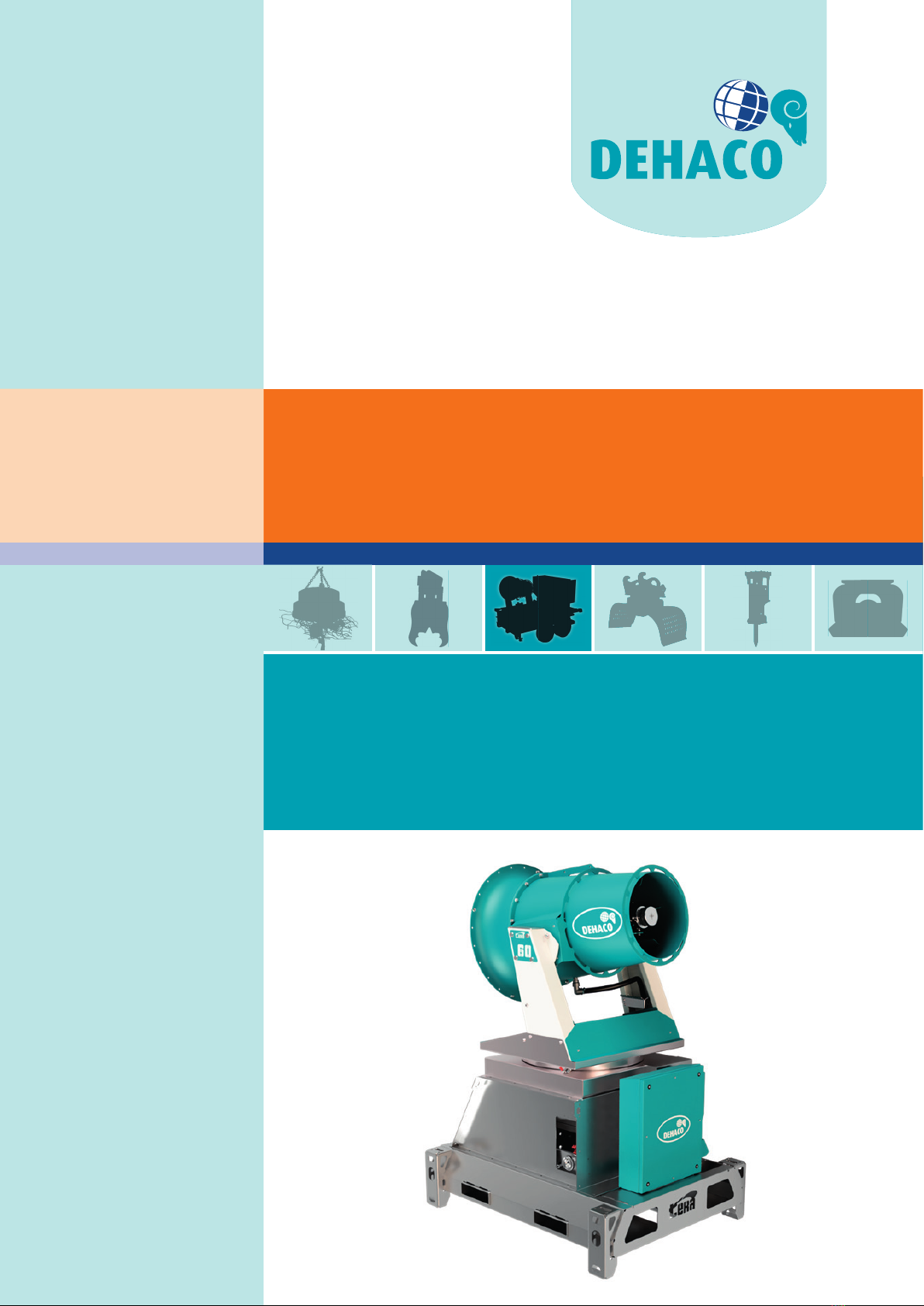
TERA 60
SERIES (2023)
User manual
English
TERA 60 • Version 01-12-2023

2Dehaco B.V. • Kruisbaak 25 • 2165 AJ Lisserbroek (NL) • ✆ +31 (0)88 - 20 20 600 • [email protected] • www.dehaco.nl

3
© 2023 Dehaco B.V. • Operation and maintenance manual TERA 60 GTM – Version 01-12-2023
Preface
© Copyright 2023, Dehaco B.V.
All rights reserved. No part of this publication can be reproduced, placed in an automated database, photocopied, copied or released into
the public domain, in any shape or form or in any other manner, be it electronic or mechanical, without prior written consent from Dehaco
B.V. This also applies to any accompanying drawings and diagrams. Dehaco B.V. retains the right to change components at any given time,
without notifying clients directly or in advance. The contents of this manual can likewise be modied without prior warning. Please contact your
supplier’s engineering department for conguration, maintenance or repair-related information not addressed in this user manual. Although
this user manual has been compiled with great care, Dehaco B.V. cannot accept responsibility for potential errors in this user manual or the
accompanying consequences.
PREFACE
Thank you for purchasing a DEHACO TERA dust control unit. You now own a machine produced using the latest
technology, when used correctly and given the proper maintenance the machine will have a long, fault free lifespan.
The purpose of this manual is to familiarize yourself with the operation, to instruct you on safe working practices, and
to provide periodic maintenance guidelines. The user manual has been compiled for everyone involved in the machine’s
commissioning, operation and maintenance.
These people must:
- Possess the knowledge and qualications needed to perform their tasks.
- Have read and understood this user manual.
- Comply with all stipulated safety instructions.
- If necessary, must possess sucient, appropriate and good quality tools.
This user manual, the type plate and the safety stickers placed on the machine feature important safety-related information
and are thus an integral part of the delivery. Store this user manual carefully and also supply it if the machine is sold to
someone else. If damaged or lost, they must be re-applied or supplied once again. These items are available from Dehaco or
your dealer.
ØMake sure that you are familiar with the contents of this user manual before you operate the machine, so you can fully and
safely use all of the machine’s features!
The delivered Dehaco TERA 60 dust control unit has already been assembled and tested, and once commissioned is ready to
use. Delivery includes the machine, the quick start manual, this user manual, electrical diagrams and the where applicable the
generator manual. Upon delivery, immediately check whether the machine is complete and undamaged. Immediately contact
your supplier if components are missing or if damage has occurred during transport.
-
Dehaco B.V.
Kruisbaak 25
2165 AJ Lisserbroek (NL)
T +31 (0) 88 20 20 600
I www.dehaco.nl
Dealer

4Dehaco B.V. • Kruisbaak 25 • 2165 AJ Lisserbroek (NL) • ✆ +31 (0)88 - 20 20 600 • [email protected] • www.dehaco.nl
EC Declaration of Conformity
Translation of original user manual according to annex 1,
section 1.7.4. of Machinery Directive 2006/42/EC.
We, Dehaco B.V., hereby declare that the products listed below comply with the essential requirements
of the above-mentioned European Directive and the following harmonised standards:
Product: TERA Dust Control Unit
Brand: Dehaco
Typeaanduiding: TERA 60
Manufacturer: Dehaco B.V.
Kruisbaak 25
NL-2165 AJ Lisserbroek
Directives: Machinery Directive, 2006/42/EG
Low Voltage Directive 2014/35/EU
EMC Directive 2014/30/EU
Standard(s) NEN-EN-ISO 12100 Risk Reduction
Place and date: Lisserbroek, December 1, 2023
Commercial director:
M. Berbée, Commercial Director

5
© 2023 Dehaco B.V. • Operation and maintenance manual TERA 60 GTM – Version 01-12-2023
Index
INDEX
1. General description 6
1.1 Safety instructions 6
1.1 Signal words 6
1.2 General description 6
1.3 Guarantee terms and conditions 6
2. Machine Overview 7
3. Intended use 8
4. Technical specications 9
4.1 Sizes and weights 9
4.2 Wear parts 9
4.3 Noise emissions 9
4.4 EMC 9
5. Safety 10
6. Storage 11
7. TRANSPORT 11
8. Use instruction 12
8.1 Installation 12
8.2 Grounding the Tera 12
8.3 Control panel 13
8.4 Operation 13
8.5 Operating the rotation function 13
8.5.1 Set up instruction 13
8.5.2 Operating the rotation function manually 13
8.5.3 Operating the rotation function
automated shuttle system 13
8.6 Switching o 15
8.7 Option: radio remote control 15
8.8 OPTION: UVC Legionella prevention system 16
8.8.1 Description 16
8.8.2 Specications 16
8.8.3 Use instructions 16
8.8.3.1 Turning on 16
8.8.3.2 Turning o 16
8.8.4 Maintenance 16
8.8.4.1 Replacing the UV lamps 16
9. Maintenance 17
10. Malfunctions 18
11. Lifting Instructions 20
11.11.1 Correct use lifting systems Tera 400V 20
11.11.2 Liting point position 20
11.11.3 Fork inserts 21
12. Legionella Prevention 22
13. Repair 23
14. End of life-span 23
15. Parts 23

6Dehaco B.V. • Kruisbaak 25 • 2165 AJ Lisserbroek (NL) • ✆ +31 (0)88 - 20 20 600 • [email protected] • www.dehaco.nl
1. General description
1. GENERAL DESCRIPTION
1.1 Safety instructions
Read these safety and operating instructions and
speci cally all safety instructions before using the TERA
dust control unit.
Follow all instructions in this operation and maintenance
manual.
Anyone responsible for transporting, installing or removing,
operating, maintaining, repairing, storing or disposing of
the TERA dust control unit must have read and understood
these safety and operating instructions.
This operation and maintenance manual belongs to the
TERA dust control unit. Keep it for the life of the product.
Ensure, if applicable, that any received amendment is
incorporated in the instructions. Hand over the safety and
operating instructions if ever you lend, rent out or sell the
TERA dust control unit.
1.1 Signal words
The signal words danger, warning, caution, and notice are
used as follows in this operation and maintenance manual:
DANGER!
Indicates a hazardous situation which, if not avoided, will
result in death or serious injury.
WARNING!
Indicates a hazardous situation which, if not avoided, could
result in death or serious injury.
CAUTION!
Indicates a hazardous situation which, if not avoided, could
result in minor or moderate injury.
NOTE
The signal word NOTE is used to address practices related
to possible property damage but not related to personal
injury.
1.2 General description
This dust control unit has been developed using the name
TERA, and has very similar components to
the previous developed TERA range 45, 60, 75 and 90. The
number represents the maximum spraying distance in
meters.
The unique feature of the Tera series is that the droplet size
can be con gured irrespective of water quantity!
The 400V Dehaco TERA dust control units have been
primarily developed for outdoor use. This units have been
produced to spray very ne water for dust control during
demolition and renovation applications, but can also be
used for a variety of other industrial purposes where
dust control or cooling is required.
The Demto Rotor Technology (DRT) transforms the
water into a ne spray, which is then dispersed by the
ventilator. Because the ventilator speed, water supply
and DRT-unit can be adjusted, it is possible to adjust
droplet size, water quantity and distribution to suit any
situation!
The Tera dust control units are available in a number of
con gurations. These include:
◊ Mounting base,
◊ Skid with insert for forklift truck.
◊ Compact skid with insert for forklift truck
◊ Wall Mount
◊ Combi Skid with generator
◊ TX with water tank
◊ GTX with generator and water tank
◊ GTM with generator, water tank and o road
undercarriage
1.3 Guarantee terms and
conditions
ØThe machine is subject to a guarantee period of 12
months after delivery, in accordance with the DEHACO
General Terms and Conditions of Delivery.
https://www.dehaco.nl/en/terms-and-conditions
ØThese conditions stipulate that, within this period, only
equipment and manufacturing errors will be repaired
free of charge, AFTER BEING EVALUATED BY DEHACO.
Transport and or travel costs must be paid by the
customer.
ØGUARANTEE CANNOT be provided for wear parts.

7
© 2023 Dehaco B.V. • Operation and maintenance manual TERA 60 GTM – Version 01-12-2023
2. Machine overview
2. MACHINE OVERVIEW
1Demto-Rotor-Technology® (DRT)
2Tilt transport lock
3 Water lter
4Water coupling
5Fan
12
5
6
8
9
10
6Fork inserts
7Rotation transport lock
8Tera control panel
9Emergency stop
10 Power socket mains/generator
7
4
3

8Dehaco B.V. • Kruisbaak 25 • 2165 AJ Lisserbroek (NL) • ✆ +31 (0)88 - 20 20 600 • [email protected] • www.dehaco.nl
3. Intended use
3. INTENDED USE
The Dehaco Tera 60 Dust control units have been developed
for: -Dust management during demolition, recycling,
renovation and raw material handling and recycling
operations
-Odour control
-Cooling
-Use with potable water
The Tera dust control units can be used in temperatures
ranging from 5 degrees Celsius to 40 degrees Celsius.
The Tera dust control units can be stored, as long as
all water is drained from the machine, in a frost free
environment and in temperatures up to 55 degrees Celsius.
-
WARNING!
Any use other than that mentioned above will relieve
Dehaco of all its responsibilities including guarantee!
Use for other purposes, or with other water qualities (incl.
mineral water, surface water, etc.) has not yet been tested
by Dehaco.
When considering other applications, please contact
Dehaco IN ADVANCE to discuss whether the machine is
actually suitable.
WARNING!
The Tera 60 Dust Control Unit does NOT
comply with the ATEX guidelines!

9
© 2023 Dehaco B.V. • Operation and maintenance manual TERA 60 GTM – Version 01-12-2023
TERA 60
Maximum throw at position 3 "Power Boost"
mtr
60
Maximum throw at position 2 "Eco-Boost" / 1 "Eco"
mtr
55 /45
Water consumption
ltr
0 - 4500
Optimal water supply pressure (min-max)
bar
3,0 (0,1 - 6,0)
Water connection Storz C52
Power consumption at position 3 "Power Boost"
kW
12,0 (500 ltr/h)
16,0 (4500 ltr/h)
Power consumption at position 2 "Eco Boost"
kW
8,0 (500 ltr/h
12,0 (4500 ltr/h)
Power consumption at position 1 "Eco"
kW
6,0 (500 ltr/h)
10,0 (4500 ltr/h)
Dimensions (l*w*h )
mm
1800x1400x2397
Weight
kg
707
Required voltage
V
400
Required amperage
A
32
Rotation adjustment 0 - 335°
Height adjustment angle (+50°/-25°) 75°
Demto-Rotor®Technology
Electrical rotation adjustment (swivel adjustment included)
Electrical height adjustment
Control panel made with switches
Water consumption gauge (throttling valve included)
Remote control
UVC water disinfection system
Cable 25 metres 32A
4. Technical speci cations
4. TECHNICAL SPECIFICATIONS
4.1 Sizes and weights
4.2 Wear parts
Wear parts are components found inside the machine,
which do not fall under the guarantee due to increased
contact with the product.
The wear parts in this machine include:
-Water lter
-Where applicable parts mentioned by the
generator manufacture
4.3 Noise emissions
-Noise levels in the immediate surroundings (1m
distance, 1,65m height) of the dust control unit
during operation have been measured.
-The maximum noise level measured at maximum
power is 98 dB.
-Due to this noise level Dehaco strongly
recommends using hearing protection.
WARNING!
Use hearing protection if you work in the immediate
surroundings of the machine!
4.4 EMC
Electromagnetic compatibility (EMC) relates to electronic
devices interfering with other devices or are interfered with
by other devices and residual current.
All of the Tera’s components comply with the standards for
use in an industrial environment (NEN-EN 61800-3).
If higher EMC requirements are required for speci c
applications of the TERA, then an optional choke coil or line
lter is available.
Please contact your dealer or Dehaco for a bespoke
solution.
4.4 EMC

10 Dehaco B.V. • Kruisbaak 25 • 2165 AJ Lisserbroek (NL) • ✆ +31 (0)88 - 20 20 600 • [email protected] • www.dehaco.nl
5. Safety
5. SAFETY
WARNING!
Almost all accidents can be attributed to: loss of
concentration, carelessness, negligence or errors in
judgment! Work calmly and in a concentrated manner.
Make sure that the workplace is always well illuminated;
possibly install extra temporary (construction) lighting to
retain a clear overview.
Everyone involved with the installation, commissioning,
operation, maintenance and repairs must:
-have the level of knowledge and quali cations
required for their task.
-have read and understood this user manual.
-comply with all indicated safety instructions.
- If necessary, must possess su cient, appropriate
and good quality tools.
WARNING!
There is immediate risk of physical injury and/or damage
to machines and the environment if the machine is used by
inexperienced and/or unquali ed persons. Keep observers
at a safe distance when the TERA is operational!
WARNING!
You must also follow the local safety regulations under all
circumstances.
WARNING!
Use personal protection equipment according to national,
local and/or at the site requirements, this should at least
include:
Øsafety helmet
Øhearing protection
Øsafety goggles
Øgloves
Øsafety footwear
CAUTION!
Regular lubrication and structural preventive
maintenance reduces the risk of malfunctions during
operation.
Please read the user manual carefully
before starting the machine.

11
© 2023 Dehaco B.V. • Operation and maintenance manual TERA 60 GTM – Version 01-12-2023
6. Storage | 7. Transport
6. STORAGE
The following actions are recommended if the machine will
not be used for an extended period of time:
NOTE
Always be careful with bearings when using a sprayer/
blower to clean the machine!
-Carefully rinse the machine using clean tap water.
DO NOT USE A HIGH PRESSURE CLEANER!
-Perform maintenance.
-Possibly apply a preservative.
-Store the machine in a dry and frost-free location.
7. TRANSPORT
CAUTION!
Ensure all the locking pins are engaged so the dust control
unit cannot rotate or tilt unexpectedly!
Each of the locking pins are indicated in the image below.
Depending on the selected version and/or options, the
dust control unit can be moved using a wheel loader, truck,
shovel, car or tractor.
NOTE
When transporting on a trailer or truck, always secure the
machine by attaching lashing straps to the lifting eyes!
NOTE
ØUse only certi ed and suitable lifting equipment when
lifting the TERA
ØConsult the speci cations for the exact weight and
dimensions of your dust control unit.

12 Dehaco B.V. • Kruisbaak 25 • 2165 AJ Lisserbroek (NL) • ✆ +31 (0)88 - 20 20 600 • [email protected] • www.dehaco.nl
8. Use
8. USE
8.1 Installation
NOTE
When using a water supply for the rst time: rst run the
water hose before it is connected! This helps to prevent
dirt from the water supply from entering or blocking the
lter or DRT!
1) Determine the most suitable location for setting up
the TERA: As close as possible to the object that must
be sprayed, but far enough to operate without being
hindered! When doing so, consider:
- the water supply,
- wind direction,
- maximum distance and
- swivel range.
2) Place the TERA dust control unit on a smooth, hardened
and reasonably horizontal surface.
3) Where applicable check the oil, coolant and diesel levels
in the generator, and the water level in the tank.
4) Inspect the water lter
5) Release both rotation and tilt transport locks to use the
rotation and tilt functions.
Rotation and tilt transport lock
8.2 Grounding the Tera
Electrical current ow, similar to water ow, takes the path
of least resistance to the ground. For safety reasons and
equipment protection, it is important to ensure that path
is not through personnel when they come in contact with
electrical equipment. E ective grounding of all circuits and
bonding looks to provide an easy path to ground when
objectionable current ow or fault occurs. A grounding rod
is standard delivered with the TERA 60 GTM / GTX.
1. Fasten the wire on the TERA 60 with the wingnut.
2. Drive the rod in the ground.
Grounding pen and wire
ØFollow the generator manual instructions!
* = GTM only

13
© 2023 Dehaco B.V. • Operation and maintenance manual TERA 60 GTM – Version 01-12-2023
8. Use
8.3 Control panel
Control panel
From left to right:
FREQ. ERROR will be illuminated if an error has been
detected by one of the frequency inverters.
POWER ERROR will be illuminated when an error has been
detected in the power supply.
FAN 1/2/3 Con gure Eco/ Eco-Boost / Power-Boost.
ROTOR 1/2/3 Con gure droplet size: Coarse/Medium/Fine.
MANUAL/AUTO makes it possible to choose between a
xed position and the automated shuttle function. The
button will illuminate in green when in AUTO setting.
Manually con gure rotation angle to the left/right.
Manually con gure tilt angle upwards/downwards.
1
0
On/O switch for the fan and rotor.
The o button is the reset button.
8.4 Operation
1. Open the TERA Control panel cover
2. Push the RESET button for at least 3 seconds.
3. Direct the Tera to the correct position
4. Select an initial fan speed.
5. Select an initial droplet size.
6. Push the start button and wait: The TERA starts
up within 10 seconds.
7. Con gure the automated shuttle function.
8. Adjust the fan speed and droplet size accordingly.
8.5.1 Operating the rotation
function
The 400V Tera series features a rotation function with an
automated shuttle system.
Setup Instructions
1) Position the Tera in a safe location where it is stable and
will not a ect the safety of others within the working
area.
2) Connect the power and water supplies.
3) Release the locking pins for the rotation and tilt
function.
4) Reset the controls by pressing the o button on the
control panel.
5) If required disengage the emergency stop button.
The dust control unit is now prepared for operation.
Control panel

14 Dehaco B.V. • Kruisbaak 25 • 2165 AJ Lisserbroek (NL) • ✆ +31 (0)88 - 20 20 600 • [email protected] • www.dehaco.nl
8. Use
8.5.2 Operating the rotation function
manually
1. Press the left button to rotate the Tera anti clockwise.
a. When you release the button the movement will
stop.
2. Press the right button to rotate the Tera clockwise.
a. When you release the button the movement will
stop.
It is possible to use the rotation function when the fan is on
and o .
8.5.3 Operating the rotation functions
automated shuttle system
1. Use the manual controls to position the Tera, aim the
Tera at the middle of the working area. Marked with
the dotted line in diagram 1 below.
2. Press the green “auto” button on the control panel to
start the automated shuttle function.
a. The operating area of the Tera in now 5°
anticlockwise of the centre line and 5° clockwise of
the centre line, see diagram 1.
3. Press the right button, also marked with a plus symbol
to increase the operating range.
a. Each time the button is pressed, the angle will
increase both clockwise and clockwise from the
centre line.
4. Press the left button, also marked with a minus symbol
to reduce the operating range.
a. Each time the button is pressed, the angle will
decrease both clockwise and clockwise from the
centre line.
The operating range can be adjusted between 0 - 335°.
If the Tera reaches the end point of the Tera, the operating
range will only increase in the opposite direction.
Control panel
Diagram 2 – Automated shuttle system adjustmentDiagram 1 – Automated shuttle system setup

15
© 2023 Dehaco B.V. • Operation and maintenance manual TERA 60 GTM – Version 01-12-2023
8. Use
8.6 Switching off
NOTE
Always switch off using the OFF button on the control
panel. Do NOT use the emergency stop button for a
default switch off , only during an emergency!
-Press the OFF button for 1 second:
The on/off switch light will blink once activated. After
the fan and rotor have nished the turn off sequence
they will stop.
-f necessary to turn the auto rotation mode o
manually
-If the Tera will be transported position the turbine
allowing the locking pins to be engaged.
-Where applicable, switch off the generator according
to the generator manufacturers user manual.
IMPORTANT!
In case of frost:
1) Open the drain valve positioned next to the main water
connection.
2) Where applicable open the UVC set drain valves.
The Tera will drain correctly when placed on a
horizontal surface.
8.7 Option: radio remote control
The Tera dust control units can be equipped with radio
remote control on the 433 Mhz frequency.
The maximum range is approximately 100 meters depending
on the surroundings.
This is an Icarus RX/TX MINI system; the original user manual
will be supplied if installed.
PLEASE READ THE MANUAL CAREFULLY BEFORE USE!
The displayed hand-held transmitter is part of the delivery.
Buttons - Functions:
0 Stand-by ON / OFF (slide switch)
1 ON fan/rotor
2 OFF fan/rotor
3 Tilt turbine UPWARDS
4. Tilt turbine DOWNWARDS
5 Rotate turbine CLOCKWISE
6 Rotate turbine COUNTER-CLOCKWISE
5+6 Shortly after each other: Automated shuttle function ON
5+6 Once again: Automated shuttle function OFF
In Automatic operation:
5 INCREASE rotation angle left and right
6 REDUCE rotation angle left and right
Con gure end point for automatic rotation:
-Put the TERA in MANUAL operation.
-Set the central point of the rotation range using
buttons 5 and 6.
-Select AUTO mode by pressing buttons 5 and then
button 6 within 1 second of each other.
When in AUTO mode button 5 and 6 are used to
increase and decrease the range of movement.
Positioning the Tera and adjusting the rotation can
be performed using the same method as the control
panel.
1
0
2
3
4
5
6
Keep the remote control in its holster!
Set the standby OFF (slide switch on the back-side of the transmitter) to extend the battery life.
Pump and DRT drain valve

16 Dehaco B.V. • Kruisbaak 25 • 2165 AJ Lisserbroek (NL) • ✆ +31 (0)88 - 20 20 600 • [email protected] • www.dehaco.nl
8.8 OPTION: UVC 6000 Legionella
prevention system
8.8.1 Description
The UVC6000 uses ultraviolet light to kill any bacteria
present in the water. This signicantly reduces the chance of
legionella and other airborne bacteria’s from being spread.
The UV unit is installed on the TERA dust control unit.
8.8.2 Specications
Type: UVC 6000
Application: TERA dust control units
Capacity: Up to 6000 l/h
Two drains have been placed under the UV unit so the unit
can be emptied in case of frost. Leave the taps open until
the TERA is restarted.
CAUTION!
If there is a chance of frost or ice forming, the UVC6000
must be drained to prevent frost-related damaged!
8.8.3 Use instruction
The UVC6000 system does not start automatically with
the Tera dust control unit. It should be operated using the
dedicated control panel.
8.8.3.1 Turning on
1) Connect the Tera dust control unit to the mains power
and reset.
2) Turn the UVC 6000 system on using the blue button.
3) The UVC lamps in the system will proceed to start
up, 2-3 minutes are required to reach the operating
window.
The control box indicates whether the UVC lamps are
working and whether water is owing through the system.
If either of these conditions are icon including the red cross
with be illuminated.
The coloured LED column on the left of the control box
indicates the UV intensity, which can interpreted as how
eectively the system is working.
• Green: Correct working
• Yellow: Reduced working.
• Red: Insucient working:
Inspect the intensity level on a regular basis.
8.8.3.2 Turning o
When the Tera dust control unit is turned o the UVC6000
system will turn o automatically.
The UVC6000 system can also be manually turned o by
pressing the blue button.
If there is a chance of frost or ice forming, the UVC6000
must be drained to prevent frost-related damaged!
1 2
4
3
Two drain points are incorporated into the system. These
should be opened when the Tera dust control unit is not is
use. It is advisable to leave these open until the dust control
unit is used again.
8.8.4 Maintenance
To ensure a good working and long lifespan the UVC6000
system requires maintenance.
The UV intensity lights will indicate if the system requires
cleaning or if the UV lamps require replacing.
8.8.4.1 Replacing the UV lamps.
Should the UV lamps require replacing the following steps
should be taken.
1. Turn the Tera dust control unit o and disconnect the
power supply.
2. Remove the surrounding cover from the UVC system.
3. Unscrew the nut and remove the lamp from the quartz
glass. These parts are very fragile, caution is essential.
4. Carefully remove the quartz glass. Never use force!
5. Clean the quartz glass using a suitable agent and a soft
cloth.
6. Ensure that all of the seals are in the correct position
when reassembling the glass. Never use force!
7. Carefully install the new lamp and hand tighten the nut
onto the housing. The lamp can only t in one position
into the housing.
8. Reconnect the cable to the top of the lamp.
9. Connect the power supply and test the working of the
lamp and ensure that the system does not leak.
8. Use

17
© 2023 Dehaco B.V. • Operation and maintenance manual TERA 60 GTM – Version 01-12-2023
9. Maintenance
9. MAINTENANCE
WARNING!
Always disconnect the power supply before inspection,
maintenance or repairs are carried out!
NOTE
Where applicable, maintenance of the generator should
be done according to the manufacturers user manual!
Daily:
ØØVisually check the machine for damage. Repair or
have any minor damage repaired. This will not only
bene t your safety but also increase the life span of the
machine.
ØKeep the machine clean! This reduces the risk of
accidents, and will help ensure its correct working!
NOTE
Clean carefully. Do not use a high pressure cleaner!
Every two months:
ØClean the machine.
ØLubricate moving parts.
Tightening torques
The following tightening torques can be used for 8.8
hexagonal bolts (Wurth):
M8x 1.25-8.8 25 Nm
M10x 1.5-8.8 50 Nm
M12x 1.75-8.8 90 Nm
M16x 2.0-8.8 220 Nm
M20x 2.5-8.8 450 Nm
CAUTION!
The fan and Rotor can NEVER be connected directly to
the mains power supply! This will cause irreparable
damage to the motors! ALWAYS connect both motors
via the frequency inverter!
The slewing ring greasing point can be reached by
removing the cover coloured in red below.

18 Dehaco B.V. • Kruisbaak 25 • 2165 AJ Lisserbroek (NL) • ✆ +31 (0)88 - 20 20 600 • [email protected] • www.dehaco.nl
10. MALFUNCTIONS
WARNING!
Only qualied and experienced persons should perform
maintenance on the Tera dust control units. To be
qualied, you must understand the instructions in this
manual, have training, and know the safety rules and
regulations of the job site.
Do not alter the physical, mechanical or electrical
operation of the dust control unit. Doing so may cause a
dangerous situation for yourself and those around you
and will void the warranty.
Do not attempt repairs you do not understand. If any
questions arise regarding a safety or maintenance
procedure, contact Dehaco or your Dehaco dealer.
Never operate poorly maintained equipment. When
maintenance is required, repair or replace parts
immediately.
Read this entire manual. All personnel must understand
the maintenance and safety procedures.
Troubleshooting guide – Tera 400V series
The Tera doesn’t work at all:
ØReset the Tera on the control panel
- Press the reset button on the control panel
ØEnsure the emergency stop button is not depressed
ØCheck the power supply is suitable for the Tera
ØTurn o any machines that may be operating on the
same power supply group
ØCheck the power cable for damage
- Replace damaged cables and cables with an insucient
rating
ØCheck the power supply’s fuses and circuit breakers
- Replace or reset and tripped fuses
- Ensure the fuses and circuit breakers are suitable
ØTest the Tera on a dierent power supply and power
group
ØCheck for any signs of damage on the electrical
components and wiring
- Replace or repair any damaged components
The power supply fault cannot be reset or repeatedly
returns:
ØThe power supply is not suitable
- Check the power supply’s capacity
ØThe power cables are damaged
- Replace any damaged cables
The internal frequency fault cannot be reset or
repeatedly returns:
ØRead the error message displayed on the frequency
invertor
- Consult the frequency invertor user manual for the
correct solution
ØCheck for any signs of damage on the electrical
components and wiring
- Replace or repair any damaged components
Water lter
The rotor doesn’t work:
ØEnsure no warning lights are showing on the control panel
- Press the reset button on the control panel
ØCheck the rotor for damage, when the power is
disconnected it should rotate easily by hand
- If it is dicult to turn the rotor it must be returned to
Dehaco
ØCheck for any signs of damage on the electrical components
and wiring
- Replace or repair any damaged components
The fan doesn’t work
ØReset the Tera on the control panel
-Press the reset button on the control panel
ØCheck for debris blocking the fan blades
- Ensuring the power supply is disconnected, remove the
debris
ØListen to the fan for a possible indication of internal damage
- Repair or replace the damaged motor
ØEnsuring the power supply is disconnected, ensure is it
possible to turn the fan blades freely
ØCheck for any signs of damage on the electrical components
and wiring
- Replace or repair any damaged components
10. Malfunctions

19
© 2023 Dehaco B.V. • Operation and maintenance manual TERA 60 GTM – Version 01-12-2023
10. Malfunctions
Very little or no water is delivered from the rotor
ØCheck that the water supply is turned on and working
ØCheck that the Tera’s water valve is open
ØCheck the lter for blockages
- Remove the lter, clean or replace it
ØRemove the hoses from the rotor to see if water is
reaching the rotor
ØInspect the internal water valve for damage
- If damaged repair or replace the required components
ØEnsure that the rotor frequency invertor is operating
correctly
- Consult the user manual is an error code is displayed
The Tera doesn’t rotate
ØReset the Tera on the control panel
- Press the reset button on the control panel
ØEnsure the retainer pin has been removed
ØCheck for any signs of damage on the rotation components
and wiring
- Replace or repair any damaged components
ØEnsure that the rotation frequency invertor is operating
correctly
- Consult the user manual is an error code is displayed
ØLubricate the slewing ring
The Tera doesn’t tilt
ØReset the Tera on the control panel (only for electrical tilt
- Press the reset button on the control panel
ØEnsure the retainer pin has been removed
ØCheck for any signs of damage on the tilt components and
wiring
- Replace or repair any damaged components
ØCheck for debris blocking the tilt mechanism
- Remove any debris
The Tera doesn’t react to the remote control
ØEnsure the remote control is turned on
ØEnsure the remote control is in range of the Tera
ØReplace the batteries of the remote control
ØEnsure the remote control has been programmed for that
particular Tera
- Consult the remote controls user manual to reprogram the
remote control
ØCheck the receiver and wiring for damage
- Replace or repair any damaged components
ØRemove any objects, especially metallic between the
transmitter and receiver
ØCheck the transmitter for damage
- Replace or repair any damaged components
ØHigh voltage cable and metallic structures can aect the
signal
During troubleshooting at electrical fault it is possible to
test the Tera without water.
When testing with water ensure that the electrical boxes
are closed and locked.

20 Dehaco B.V. • Kruisbaak 25 • 2165 AJ Lisserbroek (NL) • ✆ +31 (0)88 - 20 20 600 • [email protected] • www.dehaco.nl
11.Lifting instructions
11.LIFTING INSTRUCTIONS
11.11.1 400V Tera dust control unit
Correct lifting methods ensure the safety of users and those
in the surrounding areas. Using the correct li ting points
will prevent damage to the Tera dust suppression units.
The lifting points are indicated using this symbol.
11.11.2 Lifting point position
The correct lifting positions of each model are indicated in
red. The power and water supplies should be disconnected
prior to lifting. Ensure all of the lifting equipment is
undamaged, is in good working order and has the capacity
to lift the Tera.
Tera 15
The Tera 15 features two handles positioned on the upper
cover, these are only suitable for lifting by hand.
Tera 25
The Tera 25 features a single lifting point integrated into the
fan casing. The tilt retainer pin should be engaged prior to
lifting.
Tera 400V series
The 400V Tera series feature a lifting eye on each side of
the fan casing. The rotation and tilt retainer pins should be
engaged prior to lifting.
This manual suits for next models
1
Other DEHACO Construction Equipment manuals
Popular Construction Equipment manuals by other brands

HEIN-WERNER AUTOMOTIVE
HEIN-WERNER AUTOMOTIVE HW93809 Operating instructions & parts manual

STEINEL PROFESSIONAL
STEINEL PROFESSIONAL HG 2120 E Translation of the original operating instructions

PFT
PFT MULTIMIX 2012 operating manual

Aichi
Aichi SV06CNL Operation Manual with Maintenance Information

DXV
DXV Percy D35105104 installation instructions

Bisonte
Bisonte BB 120 Operating/safety instructions