Deif PPM 300 User manual
OPERATOR'S MANUAL
PPM 300
Protection and Power Management
4189340910O

1. About the Operator's manual
1.1 Intended users of the Operator's manual.....................................................................................................................................................................5
1.2 Software versions......................................................................................................................................................................................................................5
1.3 Symbols for general notes....................................................................................................................................................................................................5
1.4 Technical support...................................................................................................................................................................................................................... 5
1.5 Warnings and safety.................................................................................................................................................................................................................6
1.6 Legal information.......................................................................................................................................................................................................................7
2. Getting started
2.1 About controller operation................................................................................................................................................................................................... 8
2.2 About the display unit (DU 300)......................................................................................................................................................................................... 9
2.2.1 Display, LEDs, and buttons............................................................................................................................................................................................9
2.2.2 GENSET controller buttons.........................................................................................................................................................................................10
2.2.3 GENSET controller LEDs............................................................................................................................................................................................. 11
2.2.4 EMERGENCY genset controller buttons...............................................................................................................................................................12
2.2.5 EMERGENCY genset controller LEDs...................................................................................................................................................................13
2.2.6 HYBRID controller buttons.......................................................................................................................................................................................... 14
2.2.7 HYBRID controller LEDs.............................................................................................................................................................................................. 15
2.2.8 SHAFT generator controller LEDs and buttons.................................................................................................................................................. 15
2.2.9 SHORE connection controller LEDs and buttons.............................................................................................................................................. 17
2.2.10 BUS TIE breaker controller LEDs and buttons.................................................................................................................................................18
2.2.11 Screen layout.................................................................................................................................................................................................................. 19
2.2.12 About the virtual keyboard........................................................................................................................................................................................ 20
2.2.13 About the help................................................................................................................................................................................................................ 21
3. Operating the system
3.1 GENSET controller basic actions...................................................................................................................................................................................22
3.1.1 Introduction to operating the GENSET controllers............................................................................................................................................ 22
3.1.2 Change modes................................................................................................................................................................................................................. 22
3.1.3 Start the genset................................................................................................................................................................................................................ 23
3.1.4 Stop the genset................................................................................................................................................................................................................ 23
3.1.5 Close the genset breaker............................................................................................................................................................................................. 24
3.1.6 Open the genset breaker..............................................................................................................................................................................................24
3.1.7 Set genset start and stop priority.............................................................................................................................................................................. 24
3.2 EMERGENCY genset controller basic actions........................................................................................................................................................25
3.2.1 Introduction to operating the EMERGENCY genset controller.....................................................................................................................25
3.2.2 Change modes................................................................................................................................................................................................................. 25
3.2.3 Start the emergency genset........................................................................................................................................................................................26
3.2.4 Stop the emergency genset........................................................................................................................................................................................ 26
3.2.5 Close the emergency genset breaker.....................................................................................................................................................................27
3.2.6 Open the emergency genset breaker..................................................................................................................................................................... 27
3.2.7 Close the tie breaker...................................................................................................................................................................................................... 28
3.2.8 Open the tie breaker.......................................................................................................................................................................................................28
3.2.9 Test the emergency genset......................................................................................................................................................................................... 29
3.2.10 Harbour operation.........................................................................................................................................................................................................29
3.3 HYBRID controller basic actions.................................................................................................................................................................................... 30
3.3.1 Introduction to operating the HYBRID controllers..............................................................................................................................................30
3.3.2 Change modes................................................................................................................................................................................................................. 30
3.3.3 Start the inverter...............................................................................................................................................................................................................31
3.3.4 Stop the inverter...............................................................................................................................................................................................................31
OPERATOR'S MANUAL 4189340910O UK Page 2 of 94

3.3.5 Close the inverter breaker............................................................................................................................................................................................31
3.3.6 Open the inverter breaker............................................................................................................................................................................................32
3.3.7 Set inverter start and stop priority.............................................................................................................................................................................32
3.4 SHAFT generator controller basic actions................................................................................................................................................................33
3.4.1 Introduction to operating the SHAFT generator controller............................................................................................................................. 33
3.4.2 Close the shaft generator breaker............................................................................................................................................................................33
3.4.3 Open the shaft generator breaker............................................................................................................................................................................ 33
3.5 SHORE connection controller basic actions............................................................................................................................................................34
3.5.1 Introduction to operating the SHORE connection controller......................................................................................................................... 34
3.5.2 Close the shore connection breaker........................................................................................................................................................................34
3.5.3 Open the shore connection breaker........................................................................................................................................................................ 35
3.6 BUS TIE breaker controller basic actions..................................................................................................................................................................35
3.6.1 Introduction to operating the BUS TIE breaker controller...............................................................................................................................35
3.6.2 Close the bus tie breaker............................................................................................................................................................................................. 36
3.6.3 Open the bus tie breaker..............................................................................................................................................................................................36
3.7 Operator messages................................................................................................................................................................................................................37
3.7.1 Controller status texts....................................................................................................................................................................................................37
3.7.2 Operator information messages................................................................................................................................................................................38
4. Home
4.1 Home page.................................................................................................................................................................................................................................. 43
5. Log on
5.1 Log on page................................................................................................................................................................................................................................44
6. Configure
6.1 Configure page......................................................................................................................................................................................................................... 45
6.2 Date and time page.................................................................................................................................................................................................................46
6.3 View design page.................................................................................................................................................................................................................... 47
6.3.1 Add or configure a view................................................................................................................................................................................................ 48
6.4 Pair page...................................................................................................................................................................................................................................... 50
6.5 Priority page...............................................................................................................................................................................................................................51
6.6 Counters page...........................................................................................................................................................................................................................52
6.7 Parameters..................................................................................................................................................................................................................................53
6.7.1 Parameters list page...................................................................................................................................................................................................... 53
6.7.2 Parameters page............................................................................................................................................................................................................. 54
6.7.3 Configure a curve............................................................................................................................................................................................................ 55
6.8 Input/output................................................................................................................................................................................................................................ 56
6.8.1 About input/output........................................................................................................................................................................................................... 56
6.8.2 Rack or ECU selection page.......................................................................................................................................................................................58
6.8.3 Module selection page.................................................................................................................................................................................................. 59
6.8.4 Terminal selection page................................................................................................................................................................................................ 60
6.8.5 Digital input (DI) page....................................................................................................................................................................................................61
6.8.6 Digital output (DO) page...............................................................................................................................................................................................62
6.8.7 Analogue input (AI) page..............................................................................................................................................................................................63
6.8.8 Analogue output (AO or PWM) page...................................................................................................................................................................... 64
7. Alarms
7.1 Alarms page............................................................................................................................................................................................................................... 65
7.1.1 Alarm state......................................................................................................................................................................................................................... 66
OPERATOR'S MANUAL 4189340910O UK Page 3 of 94

7.1.2 Shelved alarms.................................................................................................................................................................................................................66
7.1.3 Remove from service..................................................................................................................................................................................................... 67
7.1.4 Silence horn.......................................................................................................................................................................................................................67
8. Tools
8.1 Tools page................................................................................................................................................................................................................................... 68
8.2 Backup page.............................................................................................................................................................................................................................. 69
8.3 Restore..........................................................................................................................................................................................................................................70
8.3.1 Restore restrictions.........................................................................................................................................................................................................70
8.3.2 Restore page.....................................................................................................................................................................................................................71
8.3.3 Restore selection page................................................................................................................................................................................................. 72
8.4 Regulator status.......................................................................................................................................................................................................................72
8.4.1 Regulator status AVR page.........................................................................................................................................................................................72
8.4.2 Regulator status GOV page........................................................................................................................................................................................74
8.5 Units page....................................................................................................................................................................................................................................75
8.6 Communication........................................................................................................................................................................................................................ 76
8.6.1 Controller communication page.................................................................................................................................................................................76
8.6.2 Display communication page......................................................................................................................................................................................77
9. Tools - Advanced
9.1 Tools advanced page............................................................................................................................................................................................................ 78
9.2 Controller type page.............................................................................................................................................................................................................. 79
9.3 Brightness page.......................................................................................................................................................................................................................80
9.3.1 Brightness level page.....................................................................................................................................................................................................81
9.3.2 Brightness time page..................................................................................................................................................................................................... 82
9.4 Permissions page....................................................................................................................................................................................................................83
9.4.1 Groups page......................................................................................................................................................................................................................84
9.4.2 Users page......................................................................................................................................................................................................................... 85
10. Log
10.1 Log page....................................................................................................................................................................................................................................86
10.2 DM2 Log page.........................................................................................................................................................................................................................87
11. Info
11.1 Info page.................................................................................................................................................................................................................................... 88
12. Live data
12.1 Live data page........................................................................................................................................................................................................................ 89
12.2 Visual synchronisation page..........................................................................................................................................................................................90
13. Troubleshooting
13.1 Troubleshooting the system under switchboard control............................................................................................................................... 91
13.2 Troubleshooting alarms.................................................................................................................................................................................................... 91
13.3 Troubleshooting analogue input sensor failures................................................................................................................................................ 92
13.4 Troubleshooting communication.................................................................................................................................................................................92
14. Replace internal battery
14.1 Replace battery in PCM3.1...............................................................................................................................................................................................93
15. End-of-life
15.1 Disposal of waste electrical and electronic equipment...................................................................................................................................94
OPERATOR'S MANUAL 4189340910O UK Page 4 of 94

1. About the Operator's manual
1.1 Intended users of the Operator's manual
DANGER!
Read this manual before you operate the system. Failure to do this may result in personal injury and damage to the
equipment.
The Operator's manual is primarily intended for the operator that performs daily operations with the controller. The manual includes
an overview of the LEDs, buttons and screens, as well as general operator tasks, alarms, and logs.
You can find other technical documentation for PPM 300 on deif.com.
1.2 Software versions
The information in this document corresponds to the following software versions.
PPM 300 Software versions
Software Details Version
PCM APPL Controller application 1.0.15.x
DU APPL Display unit application 1.0.15.x
PICUS PC software 1.0.15.x
1.3 Symbols for general notes
NOTE This highlights general information.
More information
This highlights where you can find more information.
Example
This shows an example.
How to ...
This gives a link to a video for help and guidance.
1.4 Technical support
If you need technical support:
1. Help:
• The display unit includes context-sensitive help.
2. Technical documentation:
• Download relevant technical documentation from www.deif.com/documentation.
3. Support:
• DEIF offers 24-hour support.
• See www.deif.com for contact details, there may be a DEIF subsidiary located near you.
• You can also e-mail [email protected].
OPERATOR'S MANUAL 4189340910O UK Page 5 of 94
4. Service:
• DEIF engineers can help with design, commissioning, operating and optimisation.
5. Training:
• DEIF regularly offers training courses at the DEIF offices worldwide.
You can read more about service and support options on www.deif.com.
1.5 Warnings and safety
Safety during installation and operation
When you install and operate the equipment, you may have to work with dangerous currents and voltages. The installation must
only be carried out by authorised personnel who understand the risks involved in working with electrical equipment.
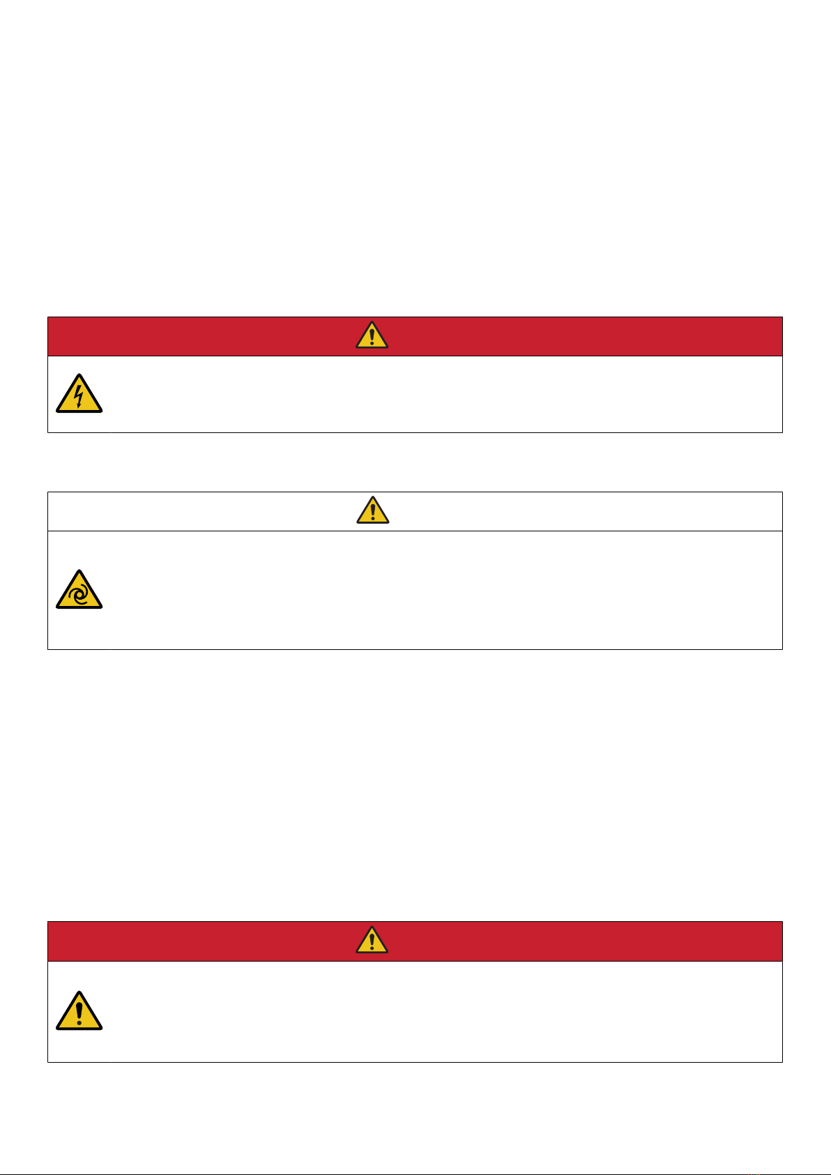
DANGER!
Hazardous live currents and voltages
Do not touch any terminals, especially the AC measurement inputs and the relay terminals, as this could lead to injury or
death.
Automatic and remote-controlled starts
CAUTION
Automatic genset start
The power management system automatically starts gensets when more power is needed. It can be difficult for an
inexperienced operator to predict which gensets will start. In addition, gensets can be started remotely (for example, via
an Ethernet connection, or a digital input).
To avoid personal injury, the genset design, the layout, and maintenance procedures must take this into account.
Switchboard control
Under Switchboard control, the operator controls and operates the equipment from the switchboard. When Switchboard control is
activated:
• The controller trips the breaker and/or shuts down the engine, if an alarm situation arises that requires a trip and/or shutdown.
• The controller does not respond to a blackout.
• The controller does not provide any power management.
• The controller does not accept operator commands.
• The controller cannot and does not prevent any manual operator actions.
The switchboard design must therefore ensure that the system is sufficiently protected when the controller is under Switchboard
control.
DANGER!
Manual override of alarm action
Do not use switchboard or manual control to override the alarm action of an active alarm.
An alarm may be active because it is latched, or because the alarm condition is still present. If the alarm action is
manually overridden, a latched alarm does NOT provide any protection.
OPERATOR'S MANUAL 4189340910O UK Page 6 of 94

1.6 Legal information
Disclaimer
DEIF A/S reserves the right to change any of the contents of this document without prior notice.
The English version of this document always contains the most recent and up-to-date information about the product. DEIF does not
take responsibility for the accuracy of translations, and translations might not be updated at the same time as the English document.
If there is a discrepancy, the English version prevails.
Warranty
The rack may only be opened to remove, replace, and/or add a hardware module or the internal battery on PCM3.1. The procedure
in the Installation instructions must be followed. If the rack is opened for any other reason, and/or the procedure is not followed,
then the warranty is void.
If the display unit is opened, then the warranty is void.
Open source software
This product contains open source software licensed under, for example, the GNU General Public License (GNU GPL) and GNU
Lesser General Public License (GNU LGPL). The source code for this software can be obtained by contacting DEIF at
[email protected]. DEIF reserves the right to charge for the cost of the service.
Trademarks
DEIF, power in control and the DEIF logo are trademarks of DEIF A/S.
Bonjour® is a registered trademark of Apple Inc. in the United States and other countries.
CANopen® is a registered community trademark of CAN in Automation e.V. (CiA).
SAE J1939® is a registered trademark of SAE International®.
CODESYS® is a trademark of CODESYS GmbH.
EtherCAT®, EtherCAT P®, Safety over EtherCAT®, are trademarks or registered trademarks, licensed by Beckhoff Automation
GmbH, Germany.
Modbus® is a registered trademark of Schneider Automation Inc.
Windows® is a registered trademark of Microsoft Corporation in the United States and other countries.
All trademarks are the properties of their respective owners.
Copyright
© Copyright DEIF A/S. All rights reserved.
OPERATOR'S MANUAL 4189340910O UK Page 7 of 94

2. Getting started
2.1 About controller operation
The PPM 300 controllers make sure that required power is available and the system is protected for typical marine applications.
Power management system (PMS) control
All controllers normally run under PMS control.
All GENSET or HYBRID controllers normally run in AUTO mode. In this mode, the PMS automatically starts and stops gensets or
inverters, according to the power requirements. The PMS also automatically closes and opens the genset or inverter breakers to the
busbar, to connect and disconnect the gensets or inverters as needed.
The SHAFT generator, SHORE connection and BUS TIE breaker controllers normally run under PMS control. These controllers do
not automatically connect to a shaft generator or shore connection, or automatically close a bus tie breaker. You need to manually
start these actions. Once you start the action, the controller automatically follows a pre-programmed sequence.
The GENSET, HYBRID, and EMERGENCY genset controllers can run in either AUTO or a semi-automatic (SEMI) mode. These are
both PMS modes. In SEMI mode, you need to manually start or stop the genset or inverter. You also need to manually start the pre-
programmed sequence to close or open the genset or inverter breaker to the busbar.
Switchboard control
Each controller can be put under switchboard control. Then you manually control the genset speed and opens and closes the
breaker. Switchboard control is useful for troubleshooting, or if you need to override the control system.
Under switchboard control, all the controller functions are disabled, but he controller protections are still active. The controller
monitors the operation, and if an alarm condition arises, the controller activates the alarm action.
Buttons and LEDs
You can use the display buttons to operate the system, for example to change modes, select actions to start pre-programmed
sequences, change genset priority, and to silence alarms. The buttons to start or stop the genset, or close or open the breakers, are
only active in SEMI mode.
You see the status of each part of the system at the display LEDs.
Display screen
From the display screen you can:
• Monitor system operation.
• Use the soft key buttons and the display screen to log on to the controller to see the alarm lists and logs, and to acknowledge
and unlatch alarms.
• See and/or change the controller configuration (some features may not be accessible due to user level permissions).
PICUS
PICUS (Power In Control Utility Software) is the PC programming and monitoring tool, available from DEIF free of charge. You
connect a computer with PICUS to the controller (direct connection), and are now able to configure, supervise, send commands and
more..
OPERATOR'S MANUAL 4189340910O UK Page 8 of 94
2.2 About the display unit (DU 300)
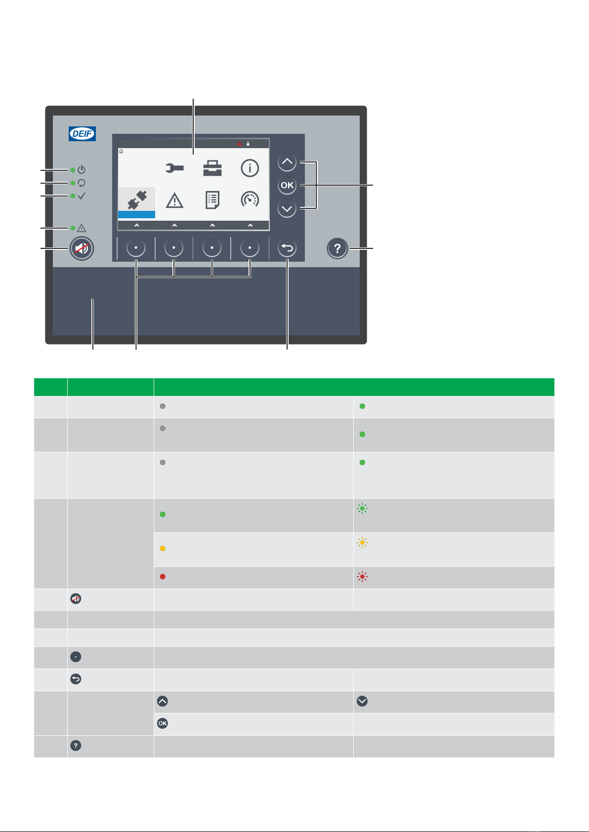
2.2.1 Display, LEDs, and buttons
Switchboard control
Home
P1
12:00
Configure Tools Info
Live dataLogAlarmLog on
1
6
9
11
2
3
4
5
7 8
10
No. Item Notes
1 Display unit power Off : Unit not powered. Green : Unit powered.
2 Self-check OK Off : Controller self-check not OK, or no
connection to the controller. Green : Controller self-check OK.
3 Ready for operation
Off : Controller under switchboard control or
an alarm action prevents source from supplying
power.
Green : Controller not under switchboard
control and no alarm action prevents the source
from supplying power.
4 Alarm
Green : No alarms. Green flash : Only cleared unacknowledged
alarms.
Yellow : Unlatched alarms can be reset. Yellow flash : Unacknowledged latched
alarms
Red : All active alarms acknowledged. Red flash : Unacknowledged alarms.
5 Horn silence Stop the horn output. Hold: Change to alarms page.
6 Screen Shows the feature or page.
7 Bottom strip LEDs and buttons for the controller type.
8 Soft key Move selection to a column, or select the soft key shown on screen.
9 Back Change to previous page. Hold: Change to home page.
10 Selection on screen
Up : Move selection up on the screen. Down : Move selection down on the screen.
OK : confirm selection on screen.
11 Help Change to help page. Hold: Change to Live data page.
OPERATOR'S MANUAL 4189340910O UK Page 9 of 94
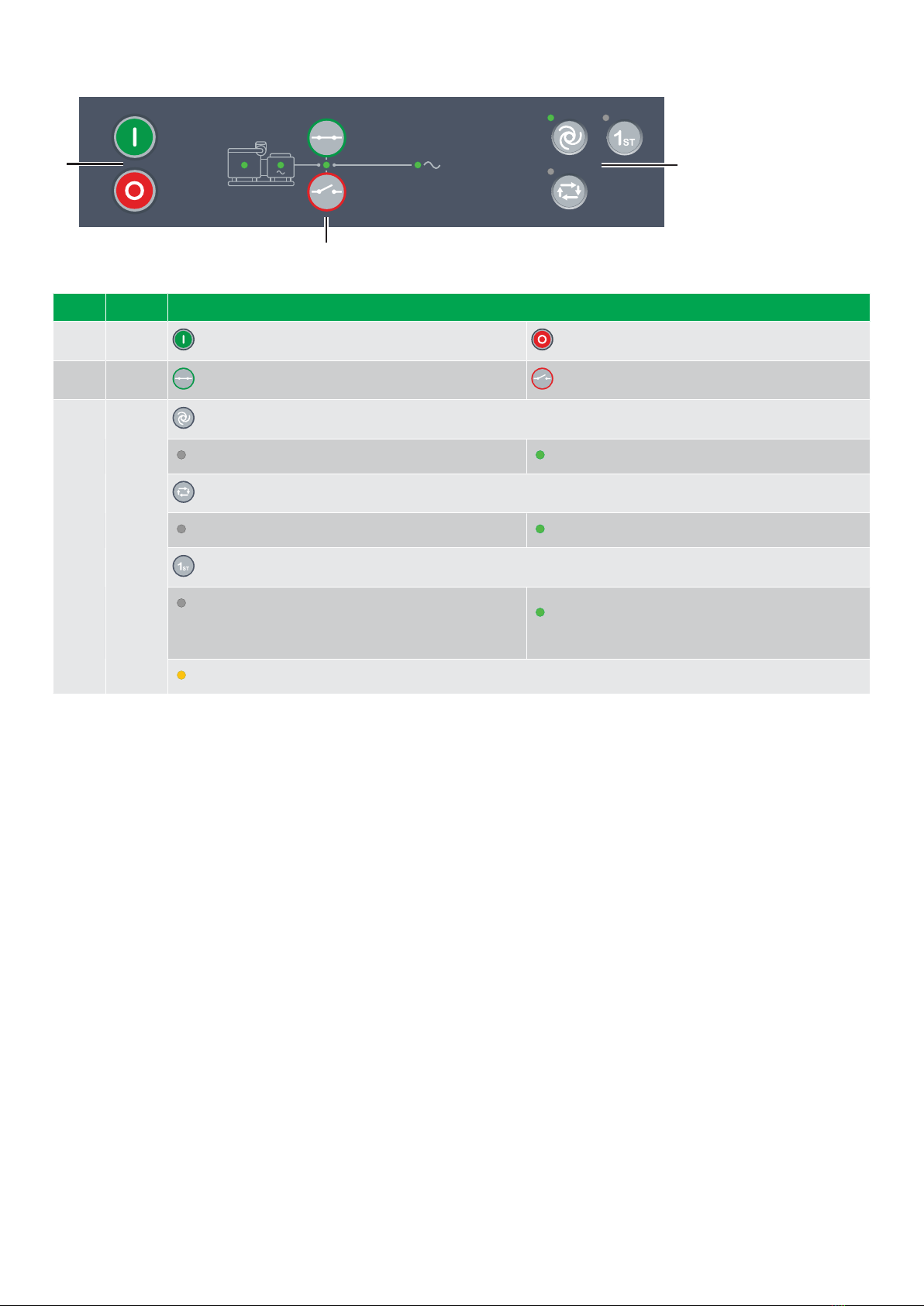
2.2.2 GENSET controller buttons
2
1 3
No. Item Notes
1 Genset Start genset and start sequence. * Stop genset and stop sequence. *
2 Breaker Close breaker : Starts close sequence. * Open breaker : Starts open sequence. *
3 Options
AUTO mode : Change to AUTO if possible. *
Off : Controller not in AUTO. Green : Controller in AUTO.
SEMI mode : Change to SEMI if possible.
Off : Controller not in SEMI. Green : Controller in SEMI.
1st: Controller gives the genset first priority in the genset start order in the power management system.
Off : Other genset has first priority, or power
management system automatically calculates genset
priority, or controller under switchboard control.
Green : Genset has first priority in the genset start
order in the power management system.
Yellow : Genset is next in the genset start order in the power management system.
NOTE * Only in SEMI mode. In AUTO or Switchboard the controller ignores the input.
OPERATOR'S MANUAL 4189340910O UK Page 10 of 94
Other manuals for PPM 300
2
Table of contents
Other Deif Control System manuals


