Deif MVR-200 Series User manual

OPERATOR'S MANUAL
Medium Voltage Relay
MVR-200 series
DEIF A/S · Frisenborgvej 33 · DK-7800 Skive
Tel.: +45 9614 9614 · Fax: +45 9614 9615
[email protected] · www.deif.com Document no.: 4189341220A

1. Introduction
1.1 About the Operator's manual.............................................................................................................................................................................................. 3
1.1.1 Intended users of the Operator's manual.................................................................................................................................................................3
1.1.2 Abbreviations....................................................................................................................................................................................................................... 3
1.1.3 Technical support............................................................................................................................................................................................................... 3
1.2 Warnings and safety.................................................................................................................................................................................................................4
1.2.1 Warnings................................................................................................................................................................................................................................4
1.2.2 Hazard markings................................................................................................................................................................................................................ 4
1.3 Legal information.......................................................................................................................................................................................................................4
1.3.1 Disclaimer..............................................................................................................................................................................................................................4
1.3.2 Copyright................................................................................................................................................................................................................................5
2. MVR-2xx overview
2.1 User interface...............................................................................................................................................................................................................................6
2.1.1 MVR-21x local panel structure..................................................................................................................................................................................... 6
2.1.2 MVR-25x local panel structure..................................................................................................................................................................................... 7
3. Using the MVR
3.1 Alarms and trips......................................................................................................................................................................................................................... 9
3.1.1 Alarm and trip indications............................................................................................................................................................................................... 9
3.2 Access control.............................................................................................................................................................................................................................9
3.2.1 User level password configuration..............................................................................................................................................................................9
3.3 Basic navigation for MVR-21x.......................................................................................................................................................................................... 11
3.3.1 Basic configuration..........................................................................................................................................................................................................11
3.3.2 Navigation in main configuration menus................................................................................................................................................................12
3.4 Menus for MVR-21x................................................................................................................................................................................................................ 12
3.4.1 General menu overview................................................................................................................................................................................................12
3.4.2 General menu................................................................................................................................................................................................................... 13
3.4.3 Protection menu............................................................................................................................................................................................................... 14
3.4.4 Control menu.....................................................................................................................................................................................................................26
3.4.5 Communication menu....................................................................................................................................................................................................37
3.4.6 Measurement menu (for all except V211)............................................................................................................................................................. 39
3.4.7 Measurement menu (MVR-V211).............................................................................................................................................................................43
3.4.8 Monitoring menu.............................................................................................................................................................................................................. 47
3.5 End-of-life.................................................................................................................................................................................................................................... 51
3.5.1 Disposal of waste electrical and electronic equipment....................................................................................................................................51
OPERATOR'S MANUAL 4189341220A UK Page 2 of 51

1. Introduction
1.1 About the Operator's manual
1.1.1 Intended users of the Operator's manual
This is the operator's manual for DEIF's Medium Voltage Relay MVR-200. The manual is for the operator who uses the controller
display unit. The manual includes an introduction to the display unit (LEDs, push-buttons and screen).
MORE INFORMATION
See the Designer's handbook for detailed function information and descriptions.
DANGER!
Read this manual before you operate the system. Failure to do this could result in personal injury and damage to the
equipment.
1.1.2 Abbreviations
CT – Current transformer
IED – Intelligent electronic device
IO – Input output
LED – Light emitting diode
MVR-21x – MVR-F201, MVR-F205, MVR-F210, MVR-F215, MVR-M210, MVR-M215, MVR-G215, MVR-T215, MVR-T216, MVR-
V211
MVR-25x – MVR-F255, MVR-M255, MVR-M257, MVR-G257, MVR-T256, MVR-T257
NC – Normally closed
NO – Normally open
RMS – Root mean square
TRMS – True root mean square
SW – Software
1.1.3 Technical support
You can read about service and support options on the DEIF website, www.deif.com. You can also find contact details on the DEIF
website.
You have the following options if you need technical support:
• Help: The display unit includes context-sensitive help.
• Technical documentation: Download all the product technical documentation from the DEIF website: www.deif.com/
documentation
• Training: DEIF regularly offers training courses at the DEIF offices worldwide.
• Support: DEIF offers 24-hour support. See www.deif.com for contact details. There may be a DEIF subsidiary located near you.
You can also e-mail [email protected].
OPERATOR'S MANUAL 4189341220A UK Page 3 of 51

• Service: DEIF engineers can help with design, commissioning, operating and optimisation.
1.2 Warnings and safety
1.2.1 Warnings
Read the documentation carefully before use, and retain for future reference. Documentation is available at http://
www.deif.com/documentation
It is the responsibility of the user to ensure that the equipment is installed, operated and used for its intended function in the manner
specified by DEIF. If this is not the case, then the safety protection provided by the equipment may be impaired.
1.2.2 Hazard markings
General warning
Electricity warning
DANGER
A high-risk hazard which will result in death or serious injury (if not avoided).
WARNING
A medium-risk hazard which could result in death or serious injury (if not avoided).
CAUTION
A low-risk hazard which could result in moderate or minor injury (if not avoided).
DANGER!
Electrical shock and arc flash
Risk of burns and electrical shock from high voltage.
Short all current transformer secondaries before breaking any current transformer connections to the controller.
WARNING
Electrical shock
Hazardous live currents and voltages.
Do not touch any terminals, especially the AC measurement inputs and the relay terminals. Only skilled personnel, who
understand the risks involved in working with electrical equipment, may do the installation. Comply with local
regulations.
1.3 Legal information
1.3.1 Disclaimer
DEIF A/S reserves the right to change any of the contents of this document without prior notice.
OPERATOR'S MANUAL 4189341220A UK Page 4 of 51

The English version of this document always contains the most recent and up-to-date information about the product. DEIF does not
take responsibility for the accuracy of translations, and translations might not be updated at the same time as the English document.
If there is a discrepancy, the English version prevails.
1.3.2 Copyright
© Copyright DEIF A/S 2019. All rights reserved.
OPERATOR'S MANUAL 4189341220A UK Page 5 of 51
2. MVR-2xx overview
2.1 User interface
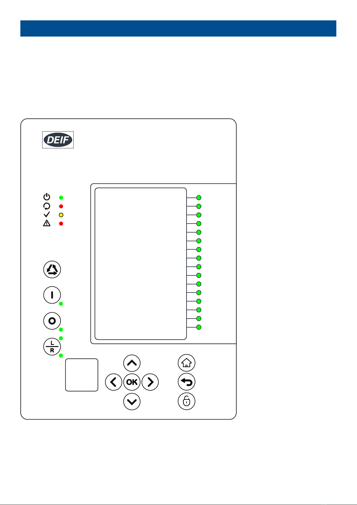
2.1.1 MVR-21x local panel structure
An MVR-21x has multiple LEDs, control buttons and local RJ-45 Ethernet port for configuration on front as a default. At the back,
each unit is equipped with RS-485 serial interface and RJ-45 Ethernet interface options as a standard. See the list below.
Figure 2.1 Local panel structure
• 4 default LEDs: Power, Error, Start (configurable) and Trip (configurable).
• 16 freely configurable LEDs with programmable legend texts.
• 3 object control buttons: Choose the controllable object with Ctrl –button, control breaker with 0- and I push-buttons.
• L/R push-button for switching between local and remote control modes.
OPERATOR'S MANUAL 4189341220A UK Page 6 of 51
• 7 navigation buttons for IED local programming and a button for password activation.
• RJ-45 Ethernet port for IED configuration.
Power LED is lit (green) when the unit is powered on. The Error LED is lit (red) when relay has an internal error that affects the
operation of the unit. This can be either a hardware or software error. The Start LED (yellow) and Trip LED (red) activation is user
settable. The activation and color (green/yellow) of the 16 LEDs on the right side of the display are user settable.
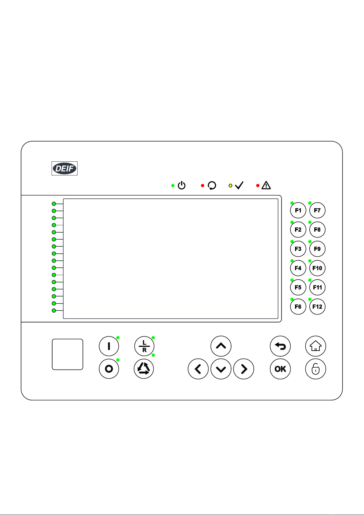
2.1.2 MVR-25x local panel structure
An MVR-25x has multiple LEDs, control buttons, function buttons and local RJ-45 Ethernet port for configuration on front as a
default. On rear each unit is equipped with RS-485 serial interface and RJ-45 Ethernet interface options as a standard. See list
below.
Figure 2.2 Local panel structure
• 4 default LEDs for free configuration: Power, Error, Start and Trip.
• 16 freely configurable LEDs with programmable legend texts.
• 3 object control buttons: Choose the controllable object with Ctrl –button, control breaker with 0- and I push buttons.
• L/R push button for local remote control.
• 7 navigation buttons for IED local programming and a button for password activation.
• 12 freely configurable function buttons.
• RJ-45 Ethernet port for IED configuration.
OPERATOR'S MANUAL 4189341220A UK Page 7 of 51

Used views are freely configurable with buttons for changing settings groups or controlling the relays logic in general. Object status
(Circuit breaker/Disconnector) can be displayed on the screen. All measured and calculated values (currents, voltages, power,
energy, frequency etc.) can be shown in the screen.
OPERATOR'S MANUAL 4189341220A UK Page 8 of 51

3. Using the MVR
3.1 Alarms and trips
3.1.1 Alarm and trip indications
MVR-21x
The Trip LED ( ) is lit whenever a protection activates a breaker trip.
For each trip, the trip name is given at the bottom of the display screen, to show the cause of the trip.
MVR-25x
The Trip LED ( ) is lit whenever a protection activates a breaker trip.
For each trip, the trip name is given at the bottom of the display screen, to show the cause of the trip.
If an LED is configured to show the trip, the LED colours are as follows:
Alarm state Details LED colour
OK There is no alarm. Green
Warning There is an alert for the operator, but no alarm action. Yellow-Orange
Trip or Fault The controller has sent a trip signal the breaker. Red
3.2 Access control
3.2.1 User level password configuration
As a factory default IEDs do not have any user levels locked behind passwords. In order to activate different user levels click the IED
HMI lock button and set the desired passwords for different user levels.
NOTE: Passwords can be set only at local HMI.
In the HMI the user level currently in use is indicated in the upper right corner with stars.
Different user levels and the indicators are:
SUPERUSER (***) = full access including configurations
CONFIGURATOR (**) = access to all settings
OPERATOR (*) = access to limited settings and control
USER ( - ) = view only
OPERATOR'S MANUAL 4189341220A UK Page 9 of 51
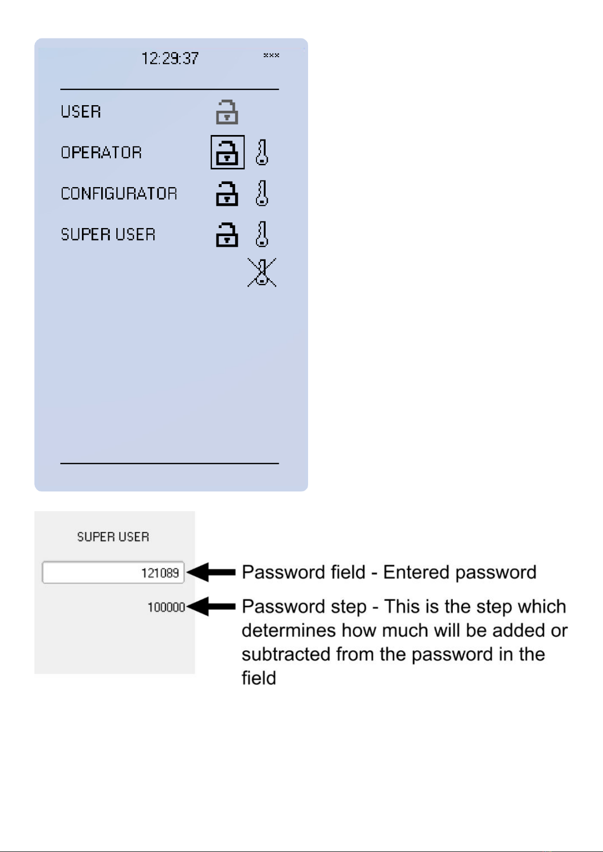
You can set a new password for the user level by selecting the key icon next to the user level. After this you can lock the user level
by pressing return key while the lock is selected. If you need to change the password you can select the key icon again and give a
new password. Please note that in order to do this the user level must be unlocked.
The required access level required to change a parameter is indicated with star (*) symbol if such is required. As a general rule the
access levels are divided as follows:
OPERATOR'S MANUAL 4189341220A UK Page 10 of 51

•User: Can view any menus and settings but cannot change any settings nor operate breakers or other equipment.
•Operator: Can view any menus and settings but cannot change any settings BUT can operate breakers or other equipment.
•Configurator: Can change most settings like basic protection pick-up levels or time delays, breaker control functions, signal
descriptions etc. Can operate breakers or other equipment.
•Super user: Access to change any setting and can operate breakers or other equipment.
3.3 Basic navigation for MVR-21x
3.3.1 Basic configuration
IED user interface is divided into 5 quick displays. The displays are Events, Favorites, Mimic, LEDs and Clock. Default quick display
is the mimic view and it is possible to glance through these menus by pressing arrows left and right. Please note that the available
quick display carousel views might be different if user has changed it with MVR Utility Software setting tools Carousel Designer.
Home button transfers the user between quick display carousel and main configuration menus. Main configuration menus are
General, Protection, Control, Communication, Measurements and Monitoring. Available menus vary depending on IED type. You
can choose the main menu by using the four arrow keys and press enter.
Figure 3.1 Basic navigation
OPERATOR'S MANUAL 4189341220A UK Page 11 of 51
• Cancel/Back key takes you one step back or holding it down for 3 seconds takes you back to general –menu. Cancel key is also
used for resetting user alarm LEDs.
• Padlock button takes user to password menu where it is possible to enter different user levels (user, operator, configurator and
super user).
3.3.2 Navigation in main configuration menus
All the settings in this IED type have been divided into main configuration menus. Main configuration menus are presented below.
Available menus may vary according to IED type.
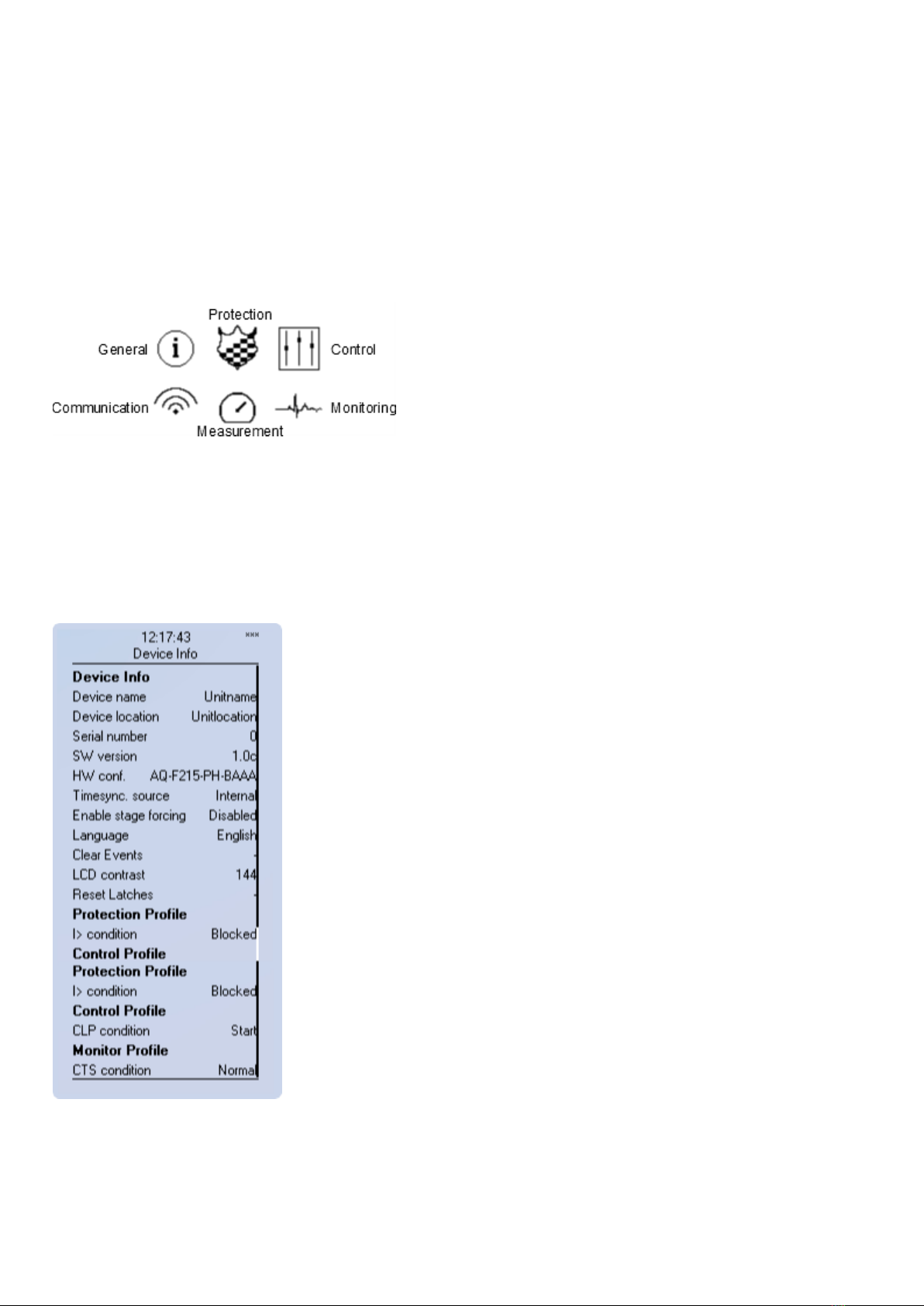
Figure 3.2 Main configuration menus
3.4 Menus for MVR-21x
3.4.1 General menu overview
Device info
Figure 3.3 Device Info sub-menu
• Set name and location of the device.
• Serial number and SW version of the IED.
• Hardware configuration (order code).
OPERATOR'S MANUAL 4189341220A UK Page 12 of 51

• Source for time synchronization, Internal or External (internal as default).
• Enable stage forcing (disabled / enabled). When forcing is disabled after using every forced output will restore. Forcing is done
individually in info menu of each stage.
• Language selection, all available languages here (English as default).
• Clear devices events.
• LCD contrast level and setting 0 to 255 (120 as default).
• Reset latched signals
• Protection/Control/Monitor profile: Displays the status of enabled functions.
3.4.2 General menu
General-menu consists of basic settings and indications of the IED. In addition to this protection, control and monitor profile displays
activated functions and their status.
Table 3.1 Parameters and indications in General-menu
Name Description Range Step Default
Device name When loading the aqs configuration file from the
MVR-200 unit the file name uses these fields.
- - Unitname
Device location - - Unitlocation
Timesync. source
If external clock time synchronization source is
available, the type is defined with this parameter. In
internal mode there is no external Timesync source.
IRIG-B requires serial fiber communication option
card.
0:Internal
1:External NTP
2:External Serial
3:IRIG-B
-0:Internal
Enable stage
forcing
When this parameter is enabled it is possible for the
user to force protection, control and monitoring
functions to different statuses like START/TRIP. This
is done in the function’s info-page with Status force
to parameter.
0:Disabled
1:Enabled - 0:Disabled
System phase
rotating order
Allows the user to switch the expected order in which
the phase measurements are wired to the unit.
0:A-B-C
1:A-C-B - 0:A-B-C
Language Changes the parameter description languages in the
HMI.
0:User defined
1:English
2:Suomi
3:Svenska
4:Español
5:Français
- 1:English
Clear events Clears the event history recorded in the MVR-200
IED.
0:-
1:Clear - 0:-
LCD Contrast Changes the contrast of the LCD display. 0…255 1 120
Display brightness Changes the display brightness. 0…8 1 4
Return to default
view
If user navigates to a menu and gives no input after
a period of time defined with this parameter the unit
will return to default view automatically. If time is set
to 0s this feature is not in use.
0…3600s 10s 0s
Reset latches
Resets latched signals in the logic and matrix. When
reset command is given the parameter will return
back to “-“ automatically.
0:-
1:Reset - 0:-
Measurement
recorder
Enables Measurement recorder tool. Measurement
recorder is configured in Tools → Misc →
Measurement recorder.
0:Disabled
1:Enabled - 0:Disabled
MIMIC reconfigure Reload the mimic to the unit. 0:-
1:Reconfigure - 0:-
OPERATOR'S MANUAL 4189341220A UK Page 13 of 51

Name Description Range Step Default
Application
Enables Railway protection specific stages
at Protection → Stage activation. Full description on
the effects of this parameter are detailed in Railway
protection module chapter.
0: Standard 3 phase
50/60Hz
1: Railroad 16,67Hz
-0: Standard 3
phase 50/60Hz
Alarm screen type Changes the type of alarm view if such is added to
carousel view.
0:Dynamic screen
1:Fixed screen
0:Dynamic
screen
0:Dynamic
screen
Table 3.2 General-menu indications
Name Description
Serial number Unique serial number identification of the unit.
SW version Units firmware software version.
HW conf. Units order code identification.
UTC time UTC time value which IED clock uses.
3.4.3 Protection menu
Protection menu includes Stage activation sub-menu and sub-menus for different protection functions like Overcurrent, Earthfault,
Seq. and balance and Supporting. Valid protection functions vary according IED type.
Figure 3.4 Protection menu view. Protection stages vary according IED type.
STAGE ACTIVATION
OPERATOR'S MANUAL 4189341220A UK Page 14 of 51

Figure 3.5 Stage activation sub-menu.
• Activation of different protection stages is done in Stage activation –sub menu. Each protection stage and supporting function is
disabled as standard.
• Activated menus will appear below the stage specific sub-menu for example I> appears below Current –module, U< appears
below Voltage-module etc.
EXAMPLE PROTECTION STAGE
Figure 3.6 Stage navigation and modification.
Each protection stage and supportive function has five stage menus Info, Settings, Registers, IO and Events.
OPERATOR'S MANUAL 4189341220A UK Page 15 of 51
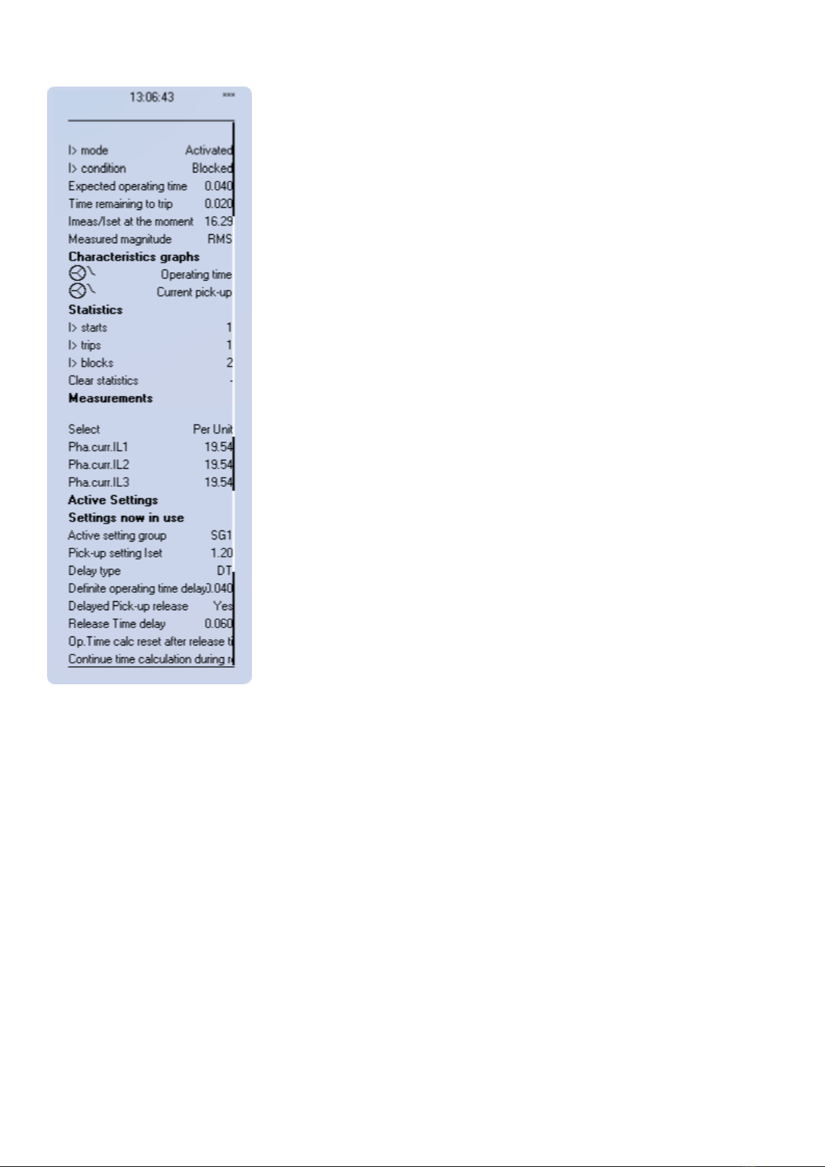
Figure 3.7 Info menu indicates all the details listed below certain protection stage or function.
• Function is activated and disabled in Stage activation menu. It is possible to disable function in Info menu as well.
• Function condition indicates whether the stages condition is Normal, Start or Trip.
• Measured amplitude can be Peak-to-peak, TRMS or RMS. As a default it is set as RMS.
• Under Characteristic graphs-title you can open graphs related to the protection function.
• Info view has calculator for function starts, trips and blockings. It is possible to clear calculators by choosing Clear statistics and
Clear.
• Measurements are visible in Info menu.
• Active setting group and its settings are all visible in Info menu.
OPERATOR'S MANUAL 4189341220A UK Page 16 of 51
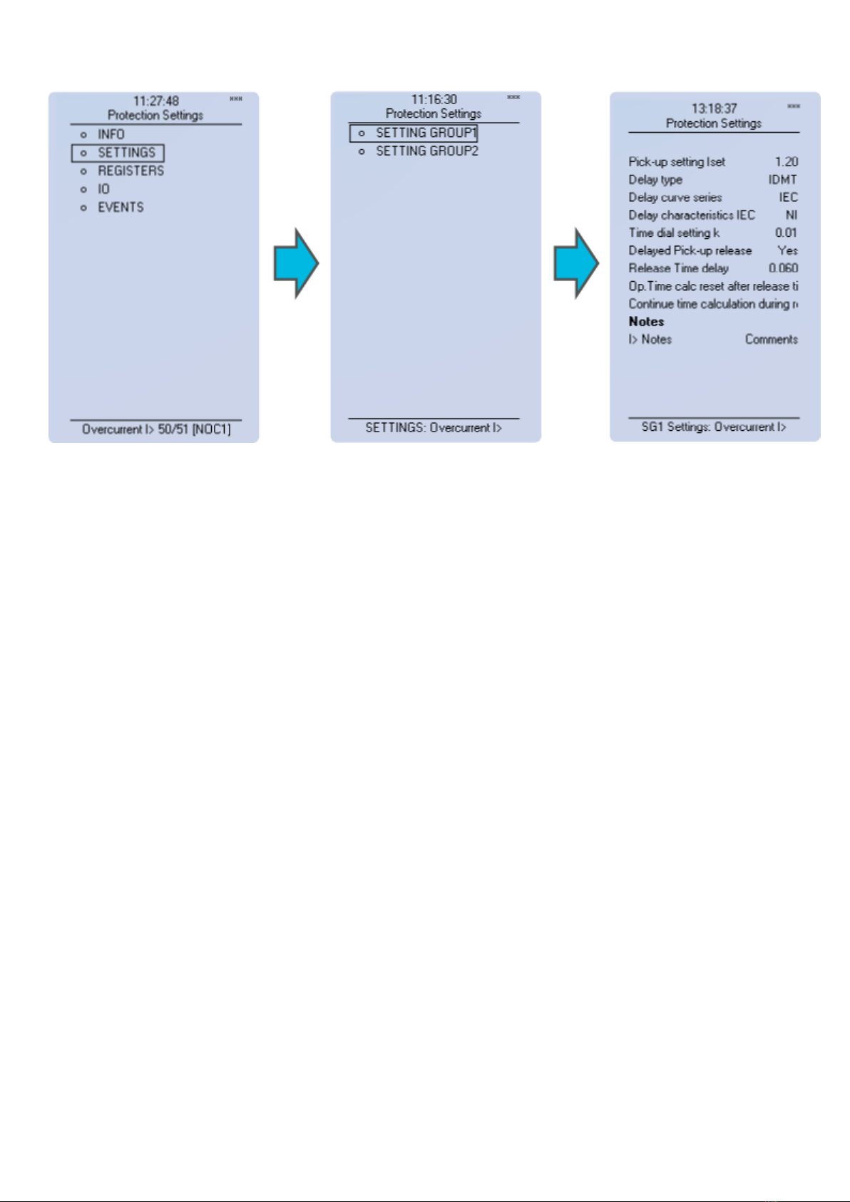
Figure 3.8 All group specific settings are done individually in Settings menu.
Stage settings vary according different protection functions. With factory settings only one group of eight is activated. To enable
more groups go to Control menu and select Setting Groups.
OPERATOR'S MANUAL 4189341220A UK Page 17 of 51

Figure 3.9 Stage information is divided into two sections.
Specific fault data of IEDs is stored in operation log under the register. Each of these 12 logs includes pre-fault current, fault current,
time stamp and active group during the triggering. Operation log can be cleared by choosing Clear registers → Clear.
Events generated by the specific stage can be checked by going to Stage event register. General events cannot be cleared.
OPERATOR'S MANUAL 4189341220A UK Page 18 of 51
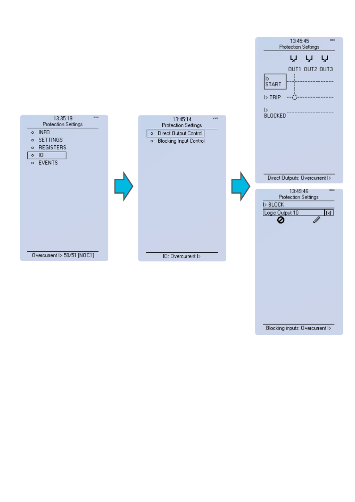
Figure 3.10 Stage information is divided into two sections.
Starting and tripping signals of protection stages are connected to physical outputs in Direct Output Control menu. It is possible to
connect to output relay or to start- trip- or user configurable LED. In case when stage is internally blocked (DI or other signal) it is
possible to configure an output to indicate that stage is blocked. Connection to outputs can be either latched |x| or non-latched x.
Stage blocking is done in Blocking Input Control menu. Blocking can be done by using digital inputs, logical inputs or outputs, stage
start- trip- or blocked information or by using object status information.
OPERATOR'S MANUAL 4189341220A UK Page 19 of 51

Figure 3.11 Protection stage related events are masked on and off individually under Events → Event mask.
Events are masked off as default. It is possible to activate desired events by masking them |x|. Only masked events appear to event
list. Events cannot be cleared.
Stage activation
Figure 3.12 Stage activation sub-menu.
•Activation of different protection stages is done in Stage activation –sub menu. Each protection stage and supporting function is
disabled as standard.
• Activated menus will appear below the stage specific sub-menu for example I> appears below Current –module, U< appears
below Voltage-module etc.
OPERATOR'S MANUAL 4189341220A UK Page 20 of 51
This manual suits for next models
2
Table of contents
Other Deif Relay manuals


