manuals.online logo
Brands
  1. Home
  2. •
  3. Brands
  4. •
  5. Panasonic
  6. •
  7. Industrial Equipment
  8. •
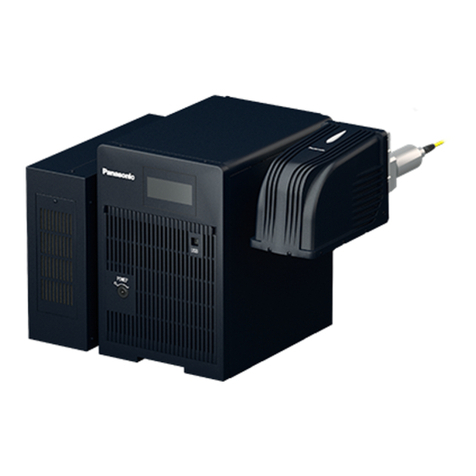
  9. Panasonic Aicure UD40 Series User manual

Panasonic Aicure UD40 Series User manual

Thank you very much for purchasing the UD40 Series Line Type LED Head.
Be sure to read this installation manual first and install this product properly.
Keep this manual in a safe place after reading this and look it up as needed.
Included Items
1
Precautions on Installation
2Consider the followings
when installing and using this product.
Power Supplies
Prepare the two types of power supplies of the following specifications for the number of
blocks to be connected.
Wiring
At connecting the power supply, please do not connect the power supply of a different
kind or in reverse polarity.
  Doing so may result in damage.
Cable to be soldered to the connector, please use the cable cross-sectional area of
larger than 0.5mm2(AWG23). Make sure to solder it properly.
  See the official website or the catalog of “NANABOSHI ELECTRIC MFG CO., LTD.” for details on
  soldering onto the connector and its handling.
Keep the cable length within 5m.
  Please contact us if you want to use the cable longer than 5m.
Hold the connector (plug) area when connecting / disconnecting the cable.
Wire the connection cable without extra load being applied.
Before Turning On the Power
Verify that the all wirings and connections are correct before turning on the power.
Installation
Do not cover up the ventilation hole.
  Doing so may result in abnormal heating.
Aicure LED Line Type UV Curing Systems
UD40 Series LED Head
Installation Manual
Safety Precautions
Please use the following precautions to prevent injuries and accidents.
Do not use this product in an environment containing flammable gas.
  Doing so may cause an explosion.
Make sure to shut off the power supply when cleaning the LED head.
  Doing so without shutting off the power supply may harm or irritate your eyes and
  skin, or may result in electric shocks.
Do not disassemble or alter the product.
  Doing so may result in accidents or injuries.
  Doing so may result in abnormal heating or fuming.
  Doing so may harm or irritate your skin by being exposed to LED-UV light.
Install this product at a place where the human body will not be exposed
to the LED-UV light.
  Being exposed to LED-UV light may harm or irritate your skin.
  When a human body is in danger of being exposed to the LED-UV light or reflected
  UV light, cover the light with an enclosure with appropriate permeability and heat
  characteristics to block the UV light.
Do not throw this product into fire.
  Doing so may cause the electrical components to explode.
Avoid placing any object on this product or block the ventilation hole.
  Doing so may result in burnout by heating.
Do not touch the terminal while the power is being supplied.
  Doing so may result in electric shocks.
Securely connect the power line and the connector.
  Improper connection may result in abnormal heating or fuming.
Prevent any foreign materials, including liquid, flammable materials and
metals, from entering into this product.
  Doing so may result in abnormal heating or fuming.
Do not perform any installation work (such as connecting or disconnecting)
with the power turned ON.
  Doing so may result in electric shocks.
Use this product in a condition sufficiently under the threshold guaranteed
or specified.
  Exceeding the threshold of the characteristics/performance guaranteed may
  damage the product.
Never look into the direct light or its reflection or expose your skin to such
light while the LED is turned ON.
  Doing so may harm or irritate your eyes and skin.
Be sure to wear protective glasses and protective gears when installing or
operating this product.
  Doing so without them may harm or irritate your eyes and skin.
  The light emitted from this product includes UV light of 365nm or 385nm
  wavelength. Make sure to wear protective glasses to block the UV light.
Do not touch with bare hands immediately after irradiation and during
irradiation.
  This product becomes very hot and may cause burn injuries.
Connect the ground wire securely.
  Doing so may result in electric shocks or malfunctions.
Do not use input power outside of the specified range.
  Doing so may result in burning out.
Do not use this product in a place where the temperature changes
drastically or a dew condensation occurs.
  Doing so may result in a malfunction.
Do not use this product at a place where extreme vibration or shock is
applied.
  Doing so may result in a malfunction.
Connector for wiring:1 set
  Connector Part No.:NJW-2824-PF16, NJW-2824-PFX16
              (NANABOSHI ELECTRIC MFG CO., LTD.)
For LED:Constant current DC power supply : Open Voltage : 40V, Max current : 3A
For Fan :Constant voltage DC power supply : DC12V±5%, Max current : 1A
Constant voltage DC power supply
: DC12V±5%, Max current : (1×number of blocks) A
Prepare the power supply of the following specifications when control the fan all at once.
Please contact us for details.
Do not touch the UV emitting window (glass) with bare hands.
  Doing so may result in smudge.
The UV emitting window is protected by the glass.
  Doing so may result in damaging the glass if a shock is applied to this area.
  If this area becomes dirty, the UV light output intensity may be degraded.
  Use alcohol (Ethanol, IPA) to wipe off smudges completely, if dirty.
Make sure to take safety measures (such as an interlock or smoke detector installation)
externally so that the entire system operates safety in case of a system failure or an
error caused by external factors.
Intake / Exhaust Direction of Fan
At the standard specification, the fan intakes the air from the side panel and exhausts
toward the back panel.
  Please contact us if you want to change the intake/exhaust direction of fan.
As an example, external dimensions of three blocks type are shown.
Dimensions of from A to C,refer to the table.
In the product of 4-6 blocks type, connectors to be connected to the main body will
be two.
Please have a margin to installation space.
Exhaust air from the fan, please do not return to the air intake area.
Warning
Caution
Be sure to
observe
Be sure to
observe
No
disassembling
Prohibited
Prohibited
General Precautions
Standard on the safety of LED products
Cables connected to this product, please use the products by our company
designation or recommended. Any malfunctions and damages occurred from use of
the other products are not covered by the product warranty.
Do not disassemble, remodel the camera or change its internal settings.
Any failure or damage arising out of using the disassembled or altered product will
not be covered by the warranty.
LED light source that is used in this product, has
become the scope of application of the
“Photobiological safety of lamps and lamp systems”
Standard:JIS C7550:2011, IEC62471:2006
Class :Risk Group 3
However, we recommend a safety management
in consideration for the safety of the user,
corresponding to the Class 4 “Standard on the
safety of laser products”
<Reference:Standard on the safety of laser products>
 Standard :JIS C6802:2011, IEC60825-1 Edition2.0:2007
 Class :Class 4 LED product
 Wavelength:365±10nm, 385±10nm
Handling of LED Products at Overseas
Currently, in JIS and IEC, LED is ordered to exemption of “Standard on the safety of
laser products”. However, since you may be adopting the old edition depending on
the country or region, please check the laser safety regulations and standards of the
country to be used.
Installation Environment
Ambient Temperature 0 to +35℃
A place free from splashes of water, oil or chemicals.
A place free from dust, oil smoke, conductive dust, corrosive or flammable gas,
salt content or iron dust.
A place free from sudden temperature changes, oscillation or shocks.
A place without direct sunlight.
A place without high magnetic field or intense electric field.
Ambient Humidity 30 to 85%RH (Without dew condensation and freezing)
UV
Dimensions
3
Unit:mm
Dimensions and Installation Space 50
or more 50
or more
50
150 or more128
A
B C
A B C
1591 72 77
2312 144 77
3033 216 77
4054 288 107
4775 360 107
5496 432 107
Number of
Blocks
Connection (Wiring)
5
Specifications
6
Wire the connection cable without extra load being applied.
Connection or disconnection, please perform in the state that power turned off.
These signals from the external device is used for detecting wavelength of LED and
the cable is connected correctly.
In Connector-1 : Connected as follows inside the LED head at LED Wavelength
If LED wavelength is 365nm, pin #1 - #2 is shorted and pin #3 is opened.
If LED wavelength is 385nm, pin #2 - #3 is shorted and pin #1 is opened.
In Connector-2 : #1, #2 and #3 is shorted.
Details of the connector pin number #1 - #3
Connector Pin Arrangement
These pins connect the constant current DC power supply for lighting the LED.
Prepare the power supplies of the following specifications for the number of blocks to
be connected.
Type of power source :Constant current DC power supply
Open voltage :DC40V (Min)
Max current :3A
The current flowing through the LED, please use less than the current value, which is
defined by specifications or the like.
Please do not mistake the polarity of the power supply to be connected.
If have a current greater than that specified, if make a mistake the polarity of the
power supply, there is a risk of damage to the LED.
Details of the connector pin number #10 - #15
These pins connect the constant voltage DC power supply for fan.
Prepare the power supplies of the following specifications for the number of blocks
to be connected.
Type of power source : Constant voltage DC power supply
(General switching power supply can be used.)
Output voltage :DC12V±5%
Max current :1A
Output voltage :DC12V±5%
Max current :(1×number of blocks) A
Prepare the power supply of the following specifications when controlling the fan all
at once.
Type of power source : Constant voltage DC power supply
(General switching power supply can be used.)
Method of wiring : Parallel connection of FAN(+)and FAN(-)
If turn on the LED, please be sure to operate the fan.
Please do not mistake the polarity of the power supply to be connected.
If you enter the wrong polarity, the fan does not operate.
There is a possibility that the fan fails.
Lighting up the LED without operating the fan may damage the LED.
Note) Please do not connect on blank terminal.
Details of the connector pin number #16 - #24
Cable to be soldered to connector
Cable cross-sectional area : Larger than 0.5mm2(AWG23)
Resistance temperature : More than 100℃
Voltage endurance : More than 100V
Length : Within 5m (Between head and power supply)
Diameter of the entire wiring : Less than 16mmφ at per connector
              (Inner diameter of connector grommet : 16mmφ)
Make sure to solder it properly.
  See the official website or the catalog of “NANABOSHI ELECTRIC MFG CO., LTD.” for
  details on soldering onto the connector and its handling.
Pin No. Block Content
1 LED 365nm
2 COM
3 LED 385nm
4
5
6
7
8
9
10 1 Anode(+)
11 1 Cathode(-)
12 2 Anode(+)
13 2 Cathode(-)
14 3 Anode(+)
15 3 Cathode(-)
16 1 FAN(+)
17
18 1 FAN(-)
19 2 FAN(+)
20
21 2 FAN(-)
22 3 FAN(+)
23
24 3 FAN(-)
Connector-1 NJW-2824-PF16
Pin No. Block Content
1
LED Connect Check 1
2 COM
3
LED Connect Check 2
4
5
6
7
8
9
10 4 Anode(+)
11 4 Cathode(-)
12 5 Anode(+)
13 5 Cathode(-)
14 6 Anode(+)
15 6 Cathode(-)
16 4 FAN(+)
17
18 4 FAN(-)
19 5 FAN(+)
20
21 5 FAN(-)
22 6 FAN(+)
23
24 6 FAN(-)
Connector-2 NJW-2824-PFX16
ANUD4A111 ANUD4A211 ANUD4A311 ANUD4A411 ANUD4A511 ANUD4A611
λ:385nm
123456
1.3kg 1.8kg 2.3kg 3.0kg 3.5kg 4.0kg
100W 200W 300W
365nm±10nm / 385nm±10nm
4,200mW/cm2(at 365nm) / 4,600mW/cm2(at 385nm)
2,300mW/cm2(at 365nm) / 2,600mW/cm2(at 385nm)
15,000 hours (70% of initial UV intensity)
400W 500W 600W
36mm 108mm 180mm 252mm 324mm 396mm
16mm 88mm 160mm 232mm 304mm 376mm
159mm 231mm 303mm 405mm 477mm 549mm
Width
Length
Height
λ:365nm
WD10mm※2
WD30mm※2
ANUD4B111 ANUD4B211 ANUD4B311 ANUD4B411 ANUD4B511 ANUD4B611
Model name
Number of blocks
Power consumption (Maximum)
Light source
Peak irradiation
intensity※1
Effective irradiation
width※1
WD10mm※2
WD30mm※2
Predicted life※1
Operating ambient temperature
Operating ambient humidity
Storage ambient temperature
Storage ambient humidity
Cooling system
Weight (Without connector and cable)
Thermistor deployment
Temperature detection of LED
0 to +35℃
30 to 85% RH (Without dew condensation and freezing)
-10 to +60℃
30 to 85% RH (Without dew condensation and freezing)
Forced air cooling by fan
Outer surface finish Cover part : A5052 (Black alumite finish)
Standard JIS C7550 / IEC 62471
50mm
142mm (Including receptacle, without connector and cable)
Size
Included Items
(Connector for wiring)※3
NJW-2824-PF16
NJW-2824-PFX16
NJW-2824-PF16
※1 It depends on our standard of measurement.
It is a representative value and is not a guarantee value.
※2 WD: Working Distance, Irradiation distance (Unit : mm)
※3 Connector made by “NANABOSHI ELECTRIC MFG CO., LTD.”
8A3 L23 7000 1
PRINTED IN JAPAN © Panasonic Industrial Devices SUNX Co., Ltd. 2014
Overseas Sales Division (Head Office)
2431-1 Ushiyama-cho, Kasugai-shi, Aichi, 486-0901, Japan
Phone: +81-568-33-7861 FAX: +81-568-33-8591
About our sale network, please visit our website.
When installed, please fix the parts firmly, use the eight M4 screws of on both sides.
(Standard of tightening torque : 1.0N·m)
Names of Part and Details of Mounting Portion
4
UV emitting window
Exhaust fan
Air intake area
Connector
Cable
Mounting screws
(Opposit side
is identical)
(Opposit side
is identical)
connection screw
F.G.
M4 depth 5.5
3010
42 40
4×M4 depth 5.5
(Opposit side
is identical)
Details of mounting portion

Other manuals for Aicure UD40 Series

2

This manual suits for next models

12

Other Panasonic Industrial Equipment manuals

Panasonic HF Series User manual

Panasonic

Panasonic HF Series User manual

Panasonic EXC28CE User manual

Panasonic

Panasonic EXC28CE User manual

Panasonic EXC24CK User manual

Panasonic

Panasonic EXC24CK User manual

Panasonic EXC14CP User manual

Panasonic

Panasonic EXC14CP User manual

Panasonic VR2 Series User manual

Panasonic

Panasonic VR2 Series User manual

Panasonic EXC14CX User manual

Panasonic

Panasonic EXC14CX User manual

Panasonic EXCX4CZ User manual

Panasonic

Panasonic EXCX4CZ User manual

Panasonic EXC14CG User manual

Panasonic

Panasonic EXC14CG User manual

Panasonic EXB 14AT Series User manual

Panasonic

Panasonic EXB 14AT Series User manual

Panasonic EXCX4CE User manual

Panasonic

Panasonic EXCX4CE User manual

Panasonic LP-GS Series Installation instructions

Panasonic

Panasonic LP-GS Series Installation instructions

Panasonic EXC16CT User manual

Panasonic

Panasonic EXC16CT User manual

Panasonic RV10C-M KXF-6Q3C User manual

Panasonic

Panasonic RV10C-M KXF-6Q3C User manual

Panasonic Tro-Reel HS User manual

Panasonic

Panasonic Tro-Reel HS User manual

Panasonic LP-GS Series Operating manual

Panasonic

Panasonic LP-GS Series Operating manual

Panasonic EXC34CG User manual

Panasonic

Panasonic EXC34CG User manual

Panasonic ERJ 2LW Series User manual

Panasonic

Panasonic ERJ 2LW Series User manual

Panasonic NAVI smart User manual

Panasonic

Panasonic NAVI smart User manual

Panasonic ERJ PA2 Series User manual

Panasonic

Panasonic ERJ PA2 Series User manual

Panasonic A35US User manual

Panasonic

Panasonic A35US User manual

Panasonic ERZVS34C201 User manual

Panasonic

Panasonic ERZVS34C201 User manual

Panasonic LP-S500W User manual

Panasonic

Panasonic LP-S500W User manual

Panasonic ERA V Series User manual

Panasonic

Panasonic ERA V Series User manual

Panasonic High-Tro-Reel User manual

Panasonic

Panasonic High-Tro-Reel User manual

Popular Industrial Equipment manuals by other brands

ABB +Q957 user manual

ABB

ABB +Q957 user manual

G.B.C BASIC EDGE 50 instruction manual

G.B.C

G.B.C BASIC EDGE 50 instruction manual

Tronair Batpak 11-6602-1000 Operation & service manual

Tronair

Tronair Batpak 11-6602-1000 Operation & service manual

Pilz PNOZ mi2p Operation manual

Pilz

Pilz PNOZ mi2p Operation manual

Clemco Zero BNP 6012 manual

Clemco

Clemco Zero BNP 6012 manual

Erskine Attachments V-Plow Operator's manual

Erskine Attachments

Erskine Attachments V-Plow Operator's manual

ABB HT610965 Operation manual

ABB

ABB HT610965 Operation manual

Morra MH 540 user manual

Morra

Morra MH 540 user manual

Eaton S090ST manual

Eaton

Eaton S090ST manual

GRIGGIO G 240 P4 instructions

GRIGGIO

GRIGGIO G 240 P4 instructions

Nexen AIR CHAMP HT45 user manual

Nexen

Nexen AIR CHAMP HT45 user manual

WTE V5 installation manual

WTE

WTE V5 installation manual

ABB HT845232 Operation manual

ABB

ABB HT845232 Operation manual

SMC Networks CJP Series Operation manual

SMC Networks

SMC Networks CJP Series Operation manual

JohnDow Industries JDI-AFT58 Operator's manual

JohnDow Industries

JohnDow Industries JDI-AFT58 Operator's manual

IMB MB9016A instruction manual

IMB

IMB MB9016A instruction manual

Clarke CUMB1 Assembly & operating instructions

Clarke

Clarke CUMB1 Assembly & operating instructions

amiad Arkal Spin Klin 2 user guide

amiad

amiad Arkal Spin Klin 2 user guide

manuals.online logo
manuals.online logoBrands
  • About & Mission
  • Contact us
  • Privacy Policy
  • Terms and Conditions

Copyright 2025 Manuals.Online. All Rights Reserved.