Delem DA-52 User manual

Manual version V0608
DA-52
Reference Manual
Operation of Version 1
English

V0608, II
Preface
This manual describes the operation of the Delem controller type DA-52 and is meant for
operators who are instructed for operation of the total machine.
Delem Limited warranty
• This manual does not entitle you to any rights. Delem reserves the right to change this
manual without prior warning.
• All rights reserved. The copyright is held by Delem. No part of this publication may be
copied or reproduced without written permission from Delem BV.

V0208, 1
Table of contents
1. Operation overview and general introduction . . . . . . . . . . . . . . . . . . . . 1.1
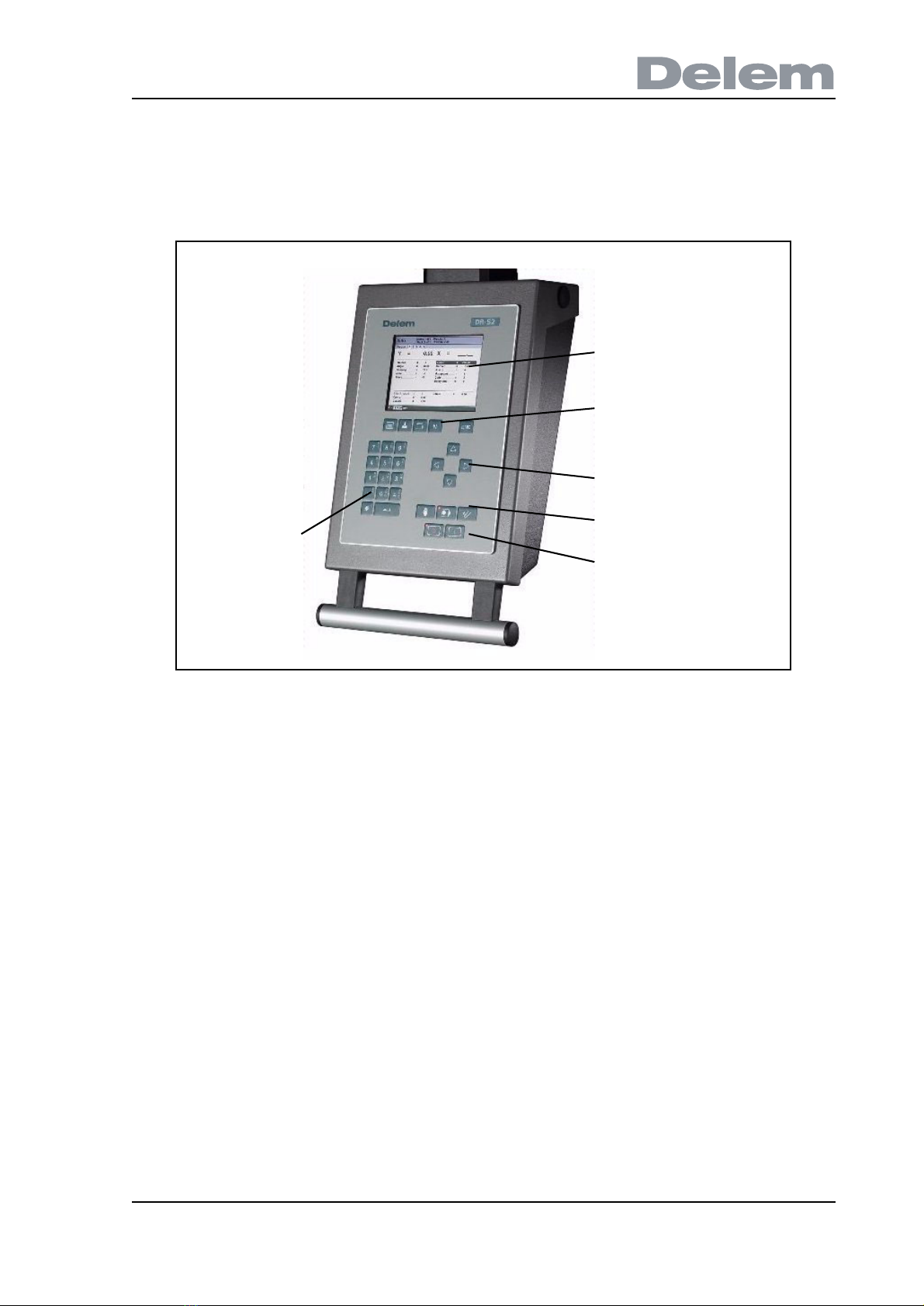
1.1. The control unit . . . . . . . . . . . . . . . . . . . . . . . . . . . . . . . . . . . . . . . . . . . . . . . . . . . . 1.1
1.2. Operation modes . . . . . . . . . . . . . . . . . . . . . . . . . . . . . . . . . . . . . . . . . . . . . . . . . . 1.2
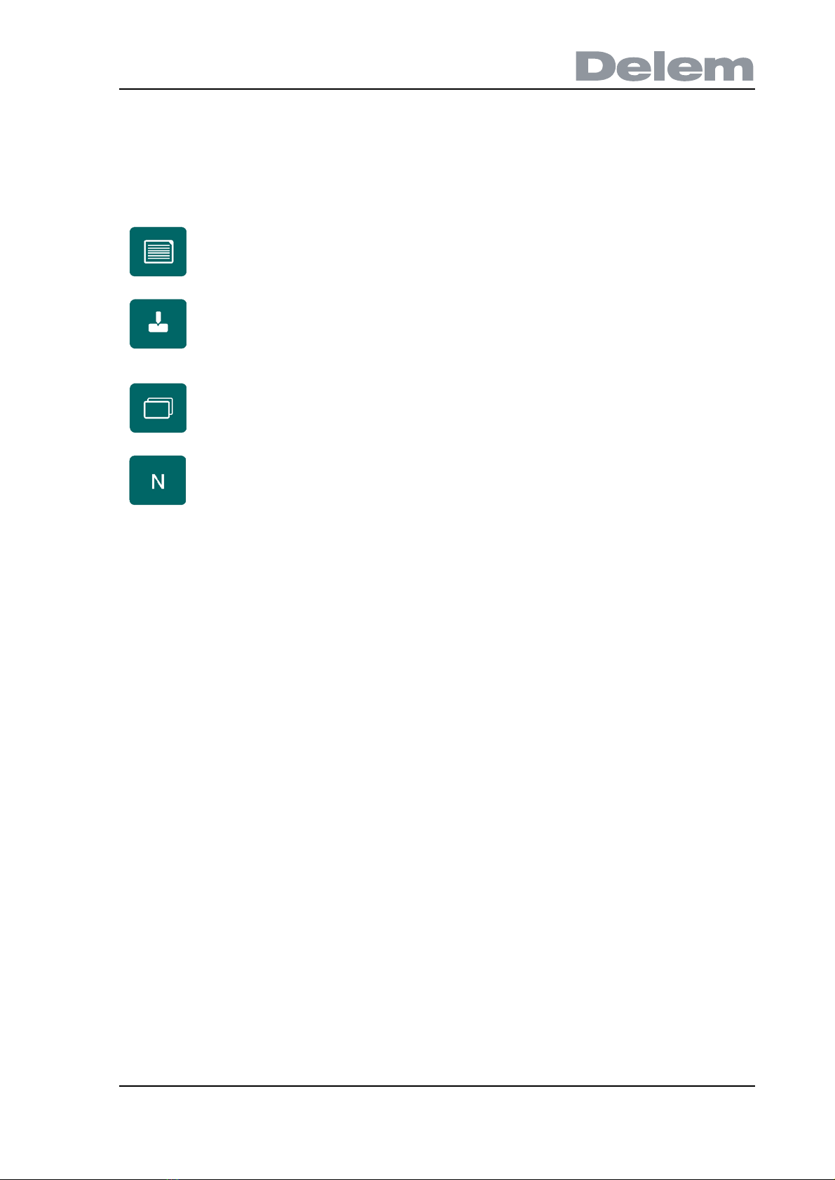
1.3. Programming modes . . . . . . . . . . . . . . . . . . . . . . . . . . . . . . . . . . . . . . . . . . . . . . . 1.3
1.4. Other frontpanel keys . . . . . . . . . . . . . . . . . . . . . . . . . . . . . . . . . . . . . . . . . . . . . . . 1.4
1.5. Software versions . . . . . . . . . . . . . . . . . . . . . . . . . . . . . . . . . . . . . . . . . . . . . . . . . . 1.5
2. Product programming . . . . . . . . . . . . . . . . . . . . . . . . . . . . . . . . . . . . . . . 2.1
2.1. Program selection . . . . . . . . . . . . . . . . . . . . . . . . . . . . . . . . . . . . . . . . . . . . . . . . . . 2.1
2.2. Program edit . . . . . . . . . . . . . . . . . . . . . . . . . . . . . . . . . . . . . . . . . . . . . . . . . . . . . . 2.2
2.2.1. General properties . . . . . . . . . . . . . . . . . . . . . . . . . . . . . . . . . . . . . . . . . . . . . 2.2
2.2.2. Parameters explanation . . . . . . . . . . . . . . . . . . . . . . . . . . . . . . . . . . . . . . . . . 2.3
2.3. Bend programming . . . . . . . . . . . . . . . . . . . . . . . . . . . . . . . . . . . . . . . . . . . . . . . . . 2.5
2.3.1. Introduction . . . . . . . . . . . . . . . . . . . . . . . . . . . . . . . . . . . . . . . . . . . . . . . . . . . 2.5
2.3.2. Bend parameters - first page . . . . . . . . . . . . . . . . . . . . . . . . . . . . . . . . . . . . . 2.5
2.3.3. Bend parameters - second page . . . . . . . . . . . . . . . . . . . . . . . . . . . . . . . . . . 2.7
3. Programming of tools . . . . . . . . . . . . . . . . . . . . . . . . . . . . . . . . . . . . . . . . 3.1
3.1. Introduction . . . . . . . . . . . . . . . . . . . . . . . . . . . . . . . . . . . . . . . . . . . . . . . . . . . . . . . 3.1
3.2. Programming of Punches . . . . . . . . . . . . . . . . . . . . . . . . . . . . . . . . . . . . . . . . . . . . 3.1
3.2.1. Punch library . . . . . . . . . . . . . . . . . . . . . . . . . . . . . . . . . . . . . . . . . . . . . . . . . . 3.1
3.2.2. Punch parameters . . . . . . . . . . . . . . . . . . . . . . . . . . . . . . . . . . . . . . . . . . . . . 3.2
3.3. Programming of bottom dies . . . . . . . . . . . . . . . . . . . . . . . . . . . . . . . . . . . . . . . . . . 3.2
3.3.1. Die library . . . . . . . . . . . . . . . . . . . . . . . . . . . . . . . . . . . . . . . . . . . . . . . . . . . . 3.2
3.3.2. Die parameters . . . . . . . . . . . . . . . . . . . . . . . . . . . . . . . . . . . . . . . . . . . . . . . . 3.3
4. Program Constants . . . . . . . . . . . . . . . . . . . . . . . . . . . . . . . . . . . . . . . . . . 4.1
4.1. Introduction . . . . . . . . . . . . . . . . . . . . . . . . . . . . . . . . . . . . . . . . . . . . . . . . . . . . . . . 4.1
4.2. General . . . . . . . . . . . . . . . . . . . . . . . . . . . . . . . . . . . . . . . . . . . . . . . . . . . . . . . . . . 4.1
4.3. Materials . . . . . . . . . . . . . . . . . . . . . . . . . . . . . . . . . . . . . . . . . . . . . . . . . . . . . . . . . 4.3
4.4. Program settings . . . . . . . . . . . . . . . . . . . . . . . . . . . . . . . . . . . . . . . . . . . . . . . . . . . 4.4
4.5. Computation settings . . . . . . . . . . . . . . . . . . . . . . . . . . . . . . . . . . . . . . . . . . . . . . . 4.6
4.6. Production settings . . . . . . . . . . . . . . . . . . . . . . . . . . . . . . . . . . . . . . . . . . . . . . . . . 4.7
4.7. Backgauge dimensions . . . . . . . . . . . . . . . . . . . . . . . . . . . . . . . . . . . . . . . . . . . . . 4.9
4.8. Maintenance . . . . . . . . . . . . . . . . . . . . . . . . . . . . . . . . . . . . . . . . . . . . . . . . . . . . . 4.10
4.9. Data transfer . . . . . . . . . . . . . . . . . . . . . . . . . . . . . . . . . . . . . . . . . . . . . . . . . . . . . 4.11
5. Manual mode . . . . . . . . . . . . . . . . . . . . . . . . . . . . . . . . . . . . . . . . . . . . . . . 5.1
5.1. Introduction . . . . . . . . . . . . . . . . . . . . . . . . . . . . . . . . . . . . . . . . . . . . . . . . . . . . . . . 5.1
5.2. Parameter Explanation . . . . . . . . . . . . . . . . . . . . . . . . . . . . . . . . . . . . . . . . . . . . . . 5.1
5.3. Zoomed values . . . . . . . . . . . . . . . . . . . . . . . . . . . . . . . . . . . . . . . . . . . . . . . . . . . . 5.4
5.4. Manual operation of the axes . . . . . . . . . . . . . . . . . . . . . . . . . . . . . . . . . . . . . . . . . 5.5
5.4.1. General . . . . . . . . . . . . . . . . . . . . . . . . . . . . . . . . . . . . . . . . . . . . . . . . . . . . . . 5.5
5.4.2. To teach . . . . . . . . . . . . . . . . . . . . . . . . . . . . . . . . . . . . . . . . . . . . . . . . . . . . . 5.6
6. Automatic mode . . . . . . . . . . . . . . . . . . . . . . . . . . . . . . . . . . . . . . . . . . . . 6.1
6.1. Introduction . . . . . . . . . . . . . . . . . . . . . . . . . . . . . . . . . . . . . . . . . . . . . . . . . . . . . . . 6.1
6.2. Parameters . . . . . . . . . . . . . . . . . . . . . . . . . . . . . . . . . . . . . . . . . . . . . . . . . . . . . . . 6.2
6.3. Zoomed values . . . . . . . . . . . . . . . . . . . . . . . . . . . . . . . . . . . . . . . . . . . . . . . . . . . . 6.3
6.4. Manual operation of the axes . . . . . . . . . . . . . . . . . . . . . . . . . . . . . . . . . . . . . . . . . 6.4
A. Parameter index . . . . . . . . . . . . . . . . . . . . . . . . . . . . . . . . . . . . . . . . . . . .A.1

V0208, 2

V0608, 1.1
1. Operation overview and general introduction
1.1. The control unit
The control looks as follows:
1.a
The precise outfit of your control may vary.
Operation of the control is done with the various keys on the front panel. A description of all
keys and their functions is given in the next section.
Beside the front panel keys, an external USB mouse can be used as a pointing device to
select menu items, parameters or softkeys. It depends on your configuration whether such a
device is available. In this manual the phrase ‘mouse’ is used to describe any of these
possible pointing devices.
screen
function keys
arrow keys
mode keys
start/stop
numeric keys

V0608, 1.2
1.2. Operation modes
The control has the 3 following modes:
Each mode can be selected by pressing the relevant push button. A LED in the push button
indicates whether or not this mode is active.
Manual mode In this mode it is possible to program all
parameters of just one bending. This mode
is useful for testing and for calibration.
Programming
mode
In this mode bend programs can be
programmed and executed.
Manual
movement
In this mode any selected axis can be
moved manually with the arrow keys.

V0608, 1.3
1.3. Programming modes
The control has the following programming functions:
You select one of the programming modes in the manual- or automatic operation mode while
the controller is in the 'stop'-status.
Program
constants
In this mode you program the general
parameters for bend programming.
Tools In this mode you program and edit the tools.
There are 30 different punches and 30
different dies to program in the program
memory.
Change view Key to switch between various pages of a
bend.
It also serves to return to an active program.
Program
library
Open the library with bend programs on the
control.

V0608, 1.4
1.4. Other frontpanel keys
The frontpanel consists of the following items:
Keyboard:
decimal point
clear key: Clearance
of the input data field
in the bottom left
corner on the monitor
screen
10 numerical keys (0-
9) incl. alphanumeric
input
plus/minus toggle
enter key, to confirm a
programmed value
Cursor path control:
Stop button Start button

V0608, 1.5
Keyswitch
The control has a keyswitch to prevent uncontrolled programming. With the keyswitch in the
off position only a selected program can be executed. The parameters cannot be changed to
wrong, unwanted values.
1.5. Software versions
The version of the software in your control is displayed at the upper side of the menu screen in
the programming mode.
Example of version number:
V 1.2
V stands for version
1 is version number
2 is version level
The version number is increased when new features are added to the software, the level
number is increased when minor corrections are needed in the existing version number.
Return to previous function or abort parameter edit.

V0608, 1.6

V0608, 2.1
2. Product programming
2.1. Program selection
To edit or create a program, proceed as follows:
The program library screen appears.
2.a
Press this key to activate the automatic mode.
Press this key to open the program library.
Use the arrow keys to move to the desired program in the list.
Use the ‘enter’ key to select the highlighted program.

V0608, 2.2
A program can also be selected by entering its number directly.
To create a new program, type a number that does not exist yet. When entered, the control
asks whether or not to create a new program.
2.2. Program edit
2.2.1. General properties
When a program has been selected (or created), a screen is shown with the general product
parameters. These parameters are the same for every bend of the program.
2.b
This page gives all data which are the same for every bending of the program (main data of
program).
Use the ‘clear’ key to delete a program. Confirm this by pressing
ENTER.
Use the arrow keys up/down to move the cursor to the
desired parameter.

V0608, 2.3
2.2.2. Parameters explanation
Drawing number . . . . . . . . . . . . . . . . . . . . . . . . . . . . . . . . . . . . . . . . ..DN
A name or description of the program. The maximum length is 20 characters.
Number of bends . . . . . . . . . . . . . . . . . . . . . . . . . . . . . . . . . . . . . . . . ..NB
The number of bends in the current program.
When this value is increased, the additional bends are copied from the last bend.
When this value is decreased, the superfluous bends are deleted.
Angle selection . . . . . . . . . . . . . . . . . . . . . . . . . . . . . . . . . . . . . . . . . ..ma
Selection of the programming mode for the Y-axis.
0 = absolute: program the absolute Y-axis position for a bend.
1 = a: program the angle to bend. The required Y-axis position is computed.
Depending on this parameter, either the parameter 'angle' or the parameter 'bend
position' will appear in a bend step.
Thickness . . . . . . . . . . . . . . . . . . . . . . . . . . . . . . . . . . . . . . . . . . . . . . ..TH
Thickness of the sheet.
Material . . . . . . . . . . . . . . . . . . . . . . . . . . . . . . . . . . . . . . . . . . . . . . . . ..M
Selection of one of the programmed materials, which are used to calculate the bending
depths. The control contains 4 preprogrammed materials and 2 programmable ones. In
total, 6 materials can be programmed on the control. See the chapter about
programming constants how to program materials.
Punch . . . . . . . . . . . . . . . . . . . . . . . . . . . . . . . . . . . . . . . . . . . . . . . . . ..UP
Number of punch in library.
Use the arrow keys left/right to browse between the
various pages of the bend program.
After pressing the enter key the programmed value will
be placed at the corresponding parameter.
E-MODULE
(N/mm²)
TENSILE
STRENGTH
(N/mm²)
1 = Steel
2 = Aluminium
3 = Zinc
4 = Stainless steel
5 = Material 5
6 = Material 6
210.000
70.000
94.000
210.000
210.000
210.000
400
200
200
700
400
400

V0608, 2.4
Die . . . . . . . . . . . . . . . . . . . . . . . . . . . . . . . . . . . . . . . . . . . . . . . . . . . . .UN
Number of die in library.
Bending length . . . . . . . . . . . . . . . . . . . . . . . . . . . . . . . . . . . . . . . . . . .BL
Length of sheet between tools.
When programming a bend, it is assumed the programmed tools have the necessary length.
2.c
Stock . . . . . . . . . . . . . . . . . . . . . . . . . . . . . . . . . . . . . . . . . . . . . . . . . . .ST
The number of products that should be created with this program.
G-Corr α. . . . . . . . . . . . . . . . . . . . . . . . . . . . . . . . . . . . . . . . . . . . . . . . .Gα=
General correction of the angle, valid for each bend of the program. The value should be
programmed in the same manner as for the correction per bend.
G-Corr X . . . . . . . . . . . . . . . . . . . . . . . . . . . . . . . . . . . . . . . . . . . . . . . . .Gx =
General correction of the X-axis position, valid for each bend of the program. The value
should be programmed in the same manner as for the correction per bend.

V0608, 2.5
2.3. Bend programming
2.3.1. Introduction
The parameters of one bend are divided over 2 screen pages. The bend number, product
number and drawing number are displayed in the top row on the screen.
2.d
The parameters below the line are corrections. They are not necessary when programming a
product, but are used to correct the machine behaviour during production. They are described
in chapter 6.
2.3.2. Bend parameters - first page
Method . . . . . . . . . . . . . . . . . . . . . . . . . . . . . . . . . . . . . . . . . . . . . . . . ..BM
Select the required bending method. The control supports 2 methods:
0 = Air bend
1 = Bottoming
Bend methods:
Use the key ‘change view’ to switch to another page
with bend parameters.
When this key is pressed again, a screen with zoomed
values appears.

V0608, 2.6
Note:
When bottoming operation is selected, the end of bend position of the Y-axis beam is
depending on the working tonnage. If however the force is sufficient for the beam to go to the
calculated Y-axis end of bend position, the beam stroke will be limited by the position value.
Angle . . . . . . . . . . . . . . . . . . . . . . . . . . . . . . . . . . . . . . . . . . . . . . . . . . .α
The required angle of this bend. This parameter only appears if angle programming is
selected with the parameter 'Angle sel.' and the bend method is an air bend.
Bend position . . . . . . . . . . . . . . . . . . . . . . . . . . . . . . . . . . . . . . . . . . . .Y
The required Y-axis position for this bend. This parameter only appears if absolute
programming is selected with the parameter 'Angle sel.' This parameter also appears if
the bend method is bottoming and/or flattening.
Opening . . . . . . . . . . . . . . . . . . . . . . . . . . . . . . . . . . . . . . . . . . . . . . . . .DY
This parameter results in a certain gap opening between the punch and the die after the
bend. A positive value is the gap opening above Mute, a negative value below Mute.
When you want to limit the handling time of the product you can program a small
positive or a negative value.
Repetition . . . . . . . . . . . . . . . . . . . . . . . . . . . . . . . . . . . . . . . . . . . . . . .CY
0 = bending is skipped.
1 through 99 = the number of times this bending will be repeated.
X-axis . . . . . . . . . . . . . . . . . . . . . . . . . . . . . . . . . . . . . . . . . . . . . . . . . . .X
Backgauge position. When a negative sign is programmed this backgauge dimension is
an incremental dimension. The incremental dimension is subtracted from the actual X-
axis position. Therefore this parameter can also be used as a chaining measure.
Retract . . . . . . . . . . . . . . . . . . . . . . . . . . . . . . . . . . . . . . . . . . . . . . . . . .DX
Retract distance of backgauge during the bending. The "backgauge retract" is started at
the pinching point of the sheet.
Auxiliary axis. . . . . . . . . . . . . . . . . . . . . . . . . . . . . . . . . . . . . . . . . . . . .R/Z/Aux.
If you have one or more auxiliary axes (for instance a R-axis, Z-axis or part support) the
air bend The sheet is bent to the programmed angle
by bringing the punch to the required depth.
The control calculates the required Y-axis
position to obtain the programmed angle.
bottoming The sheet is bent by squeezing the sheet
between the punch and the die. The control
assumes the bottom of the die as required Y-
axis position.

V0608, 2.7
parameters of these axes appear here.
2.3.3. Bend parameters - second page
2.e
This page contains the additional parameters of a bend.
Force. . . . . . . . . . . . . . . . . . . . . . . . . . . . . . . . . . . . . . . . . . . . . . . . . . ..P
The required force during pressing (auto computed).
This force is precomputed from the bend properties Material, Thickness, Bending length
and the V-opening of the die.
Speed . . . . . . . . . . . . . . . . . . . . . . . . . . . . . . . . . . . . . . . . . . . . . . . . . ..V
Working speed (pressing speed). Initially, the value for this parameter is copied from the
parameter ‘pressing speed’ in the programming constants menu.
Dwell time. . . . . . . . . . . . . . . . . . . . . . . . . . . . . . . . . . . . . . . . . . . . . . ..T
Holding time of punch at bending point.
Decompression . . . . . . . . . . . . . . . . . . . . . . . . . . . . . . . . . . . . . . . . . ..DC
Decompression stroke after bending to release the working pressure
Decomp speed . . . . . . . . . . . . . . . . . . . . . . . . . . . . . . . . . . . . . . . . . . ..BS
The decompression speed is the programmable speed which is active during the
programmed decompression stroke.
Code . . . . . . . . . . . . . . . . . . . . . . . . . . . . . . . . . . . . . . . . . . . . . . . . . . ..CX
Programmable parameter which determines when the parameter values for the next
bending will be active. The possibilities are:
0 = Bending number change (step change) at end of decompression (next bend

V0608, 2.8
parameters active).
1 = Step change at muting position when the beam moves in opening direction.
2 = Step change at upper dead point.
3 = Step change at upper dead point without movement of any axis and the control goes
to "stop".
4 = Step change if C-input signal becomes active, without movement of the beam. When
you still have a beam movement there will be no retract function of the backgauge
performed. See also code 5.
5 = Step change if C-input signal becomes active and the beam is in the upper dead
point. Now you may move the beam and the retract function of the backgauge will be
performed.
10= Step change at end of decompression with the Y-axis beam waiting at the pinching
point until the backgauge is at the retract position.
11= Step change at mute position when the beam moves in the opening direction, with
the Y-axis beam waiting at the pinching point until the backgauge is at the retract
position.
12= Step change at upper dead point, with the Y-axis beam waiting at the pinching point
until the backgauge is at the retract position.
13= Step change at upper dead point without movement of any axis. The Y-axis beam
will wait at the sheet clamp point until the backgauge is at the retract position. After the
bending with this code, the control goes to "stop".
15= Step change if C-input signal becomes active and the beam is in the upper dead
point. The beam may be moved but not necessarily. The Y-axis beam will wait at the
sheet clamp point until the backgauge is at the retract position.
The not mentioned CX-values have no meaning.
Delay time . . . . . . . . . . . . . . . . . . . . . . . . . . . . . . . . . . . . . . . . . . . . . . .TX
Programmable delay time before step change (0-30sec).
Parallelism . . . . . . . . . . . . . . . . . . . . . . . . . . . . . . . . . . . . . . . . . . . . . . .Y2
Difference of left- and right hand side cylinder (Y1 and Y2). When positive, right hand
side lower. When negative, right hand side higher. The programmed value is active
below the clamping point.

V0608, 2.9
2.f

V0608, 2.10
Table of contents
Other Delem Controllers manuals
Popular Controllers manuals by other brands

S.R.Smith
S.R.Smith WPC2 T Series installation instructions

Regin
Regin EXOCLEVER EC-PU4-2 manual

Gemu
Gemu ADA Series operating instructions

TemperZone
TemperZone UC7 quick reference

Phoenix Contact
Phoenix Contact AUTOMATIONWORX IBS PCI SC/I-T user manual

Lattice Semiconductor
Lattice Semiconductor ispLever Core Multi-Channel DMA Controller user guide