Delfin Bisky 400 User manual

Bisky
Instruction manual

pag.ii
Bisky_firsth_page_en.fm
Bisky
This page has been intentionally left blank

pag.1
Bisky_en_03TOC.fm
Bisky
Chapter 1 General Information............................................................................................ 2
1.1 List of documents.................................................................................................. 2
1.2 This instruction manual......................................................................................... 2
1.3 Property................................................................................................................. 3
1.4 Conventions.......................................................................................................... 4
1.5 Manufacturer's identification detail........................................................................ 4
1.6 Machine identification data.................................................................................... 5
1.7 EC conformity declaration..................................................................................... 5
1.8 Warranty................................................................................................................ 6
1.9 Technical assistance............................................................................................. 7
1.10 Use of the manual................................................................................................. 7
1.11 Machine description.............................................................................................. 8
Chapter 2 Information on the safety features.................................................................... 9
2.1 Safety criteria........................................................................................................ 9
2.2 Personnel qualifications...................................................................................... 10
2.3 Safety rules......................................................................................................... 11
2.4 Protections.......................................................................................................... 12
2.5 Interlocking devices............................................................................................. 13
2.6 Safety devices..................................................................................................... 14
2.7 Signs illustrating the dangers on the machine .................................................... 15
2.8 Dangerous zones and residual risks................................................................... 17
2.9 Noise emission.................................................................................................... 19
Chapter 3 Machine Characteristics................................................................................... 21
3.1 Machine specifications........................................................................................ 21
3.2 Qualified operator................................................................................................ 22
3.3 Transport............................................................................................................. 23
3.4 Preliminary operations ........................................................................................ 25
3.5 Storing of the machine ........................................................................................ 26
3.6 Allocation............................................................................................................. 27
3.7 Installation of the machine .................................................................................. 28
3.8 Machine testing................................................................................................... 28
Chapter 4 Operator interface............................................................................................. 31
4.1 Main control panel............................................................................................... 31
Chapter 5 Machine programming...................................................................................... 33
5.1 Tooling, adjustments and setting up of the machine ........................................... 33
5.2 Recipes............................................................................................................... 34
Chapter 6 Use ..................................................................................................................... 61
6.1 Dangerous areas and residual risks during the use............................................ 61

pag.2
Bisky_en_03TOC.fm
Bisky
6.2 Operators qualification........................................................................................ 61
6.3 Working area ...................................................................................................... 61
6.4 Functioning methods .......................................................................................... 62
6.5 Starting of the machine....................................................................................... 62
6.6 Starting of the machine....................................................................................... 63
6.7 Emergency stop.................................................................................................. 63
6.8 The re-starting of the machine after an emergency has been activated............. 63
6.9 Description of the procedures............................................................................. 64
6.10 Recipe management pages................................................................................ 68
6.11 Switching off the machine................................................................................... 72
6.12 Introduction of the tray........................................................................................ 72
6.13 Introduction of the rotary, fixed or wire cut plates............................................... 73
6.14 Wire cut optional................................................................................................. 74
6.15 Dismantling the hopper....................................................................................... 77
Chapter 7 Maintenance...................................................................................................... 81
7.1 Hygienic regulations to respect during the machine cleaning and washing of the
machine. 81
7.2 Standard maintenance........................................................................................ 81
7.3 Cleaning method................................................................................................. 86
7.4 Programmed maintenance ................................................................................. 87
7.5 Dismantling of the conveyor belts....................................................................... 89
7.6 Scrapping and disposing of the machine............................................................ 90
Chapter 8 Adjusting the height of the dough extrusion table....................................... 93
8.1 Height adjustment............................................................................................... 93
Chapter 20 Attached list of documents.............................................................................. 95

pag.1
01_info_gen_en.fm
Bisky
Dear Customer,
Thank you for having chosen our machine. We take the pleasure to
supply you with this instruction manual, with the objective to help
you operate our machine efficiently and safely.
We invite you to read the contents with utmost care and make sure
that all the personnel that operate, maintain, repair and eventually
dismantle the machine fully understand the contents.
We are at your disposal for any further information that you may
require on the machine or on any idea to improve the machine
functions, safety and manual.
We remind you that we have at your disposal our technical
assistance office for any questions you may have for repairs and
maintenance, this to ensure the maximum security to the personnel
and to ensure a long machine life.
Kind regards
The Manufacturer

pag.2
01_info_gen_en.fm
General Information
Bisky
Chapter 1 General Information
1.1 List of documents
• Instruction manual (this instruction manual).
1.2 This instruction manual
Manual's datas
Instruction manual:
Bisky
•Edition:2.0
• Year and month it was printed : August 2009
Addressees
• Transport of the machine.
• Installation.
• Operator.
• Maintenance.

pag.3
01_info_gen_en.fm
General Information
Bisky
1.3 Property
The information in this manual is reserved property, all rights are reserved.
This manual cannot be reproduced or photocopied in any of its parts without
having requested written permission to the Manufacturer.
This instruction manual is addressed to the owner, user of the machine, to managers or
employees with appointed responsibility, to personnel in charge of handling, installing,
operating, watching, maintaining, dismantling ect. the machine.
The Manufacturer declares that the information contained in this manual are relative to the
technical specifications and safety devices of this machine.
The Manufacturer is not responsible for direct or indirectinjury to persons, things or domestic
animals
subsequent to the incorrect use of the machine or due to conditions other than
recommended in this manual.
The Manufacturer reserves the right to update this manual and the machines of the same
model but
with different serial numbers without any prior notice.
The information contained in this manual refer to the machine specified
Machine identification data
on page 5.

pag.4
01_info_gen_en.fm
General Information
Bisky
1.4 Conventions
Meanings and symbols
• Left, right : refers to the operators position when standing in front of the operating
panel.
• Qualified personnel : people with experience, and specific training, in depth
knowledge of the safety regulations and all the relative instructions of how to avoid injury
to people, or any other danger.
Typogrphical conventions
Writings with big characters and dark black characters : Indicates the title of a chapter or a
paragraph of a chapter, or a table or a drawing identification
DPI: Individual Protection Device.
Represents a number, for example , indicates the start button on the control
panel.
represents a letter, for example indicates a part on the machine.
NOTE The notes contain very important information, evidenced in a separate
paragraph and in dark letters.
BEWARE Are important information that help avoid damage to the machine or other
equipment connected to the machine.
DANGER Are important information the can avoid injury to the personnel responsible
for the machine in all its life span..
1.5 Manufacturer's identification detail
Delfin Srl
Plant: Via Keplero, 18
36034 Malo (VI) ITALY
Tel. 039/0445/580688
Fax. 039/0445/587112
E-mail: [email protected]
Internet: http://www.delfin.it

pag.5
01_info_gen_en.fm
General Information
Bisky
1.6 Machine identification data
Type:
Model: Bisky
Serial number:
Year of construction:
Fig. 1.1 Identification plate
Machine type____________________________ Volt____________
Model__________________________________ Hz_____________
Serial number________________________________ Kw_____________
Year of construction_______________________Phase____________
Certificate of origin______________________ Weight___________
1.7 EC conformity declaration
Vedere
Attached list of documents
Document 1 EC Conformity declaration
on page 95.
pag.6
01_info_gen_en.fm
General Information
Bisky
1.8 Warranty
General conditions
1. The warranty is 12 months from the effective delivery date of the machine. Any
defects are to be notified in writing to the manufacturer within 8 days from there
being.
2. If during this period structural defects or faults on material appear, the defected parts
will be replaced or repaired free of charge.
3. We do not acknowledge damages due to overloads, improper use, wear or tear due
to climatic conditions.
4. All transport charges, costs and custom taxes due to the replacement of defected
parts are at the buyers expense.
5. Replacement and repairs are subject to the execution of the payment terms by the
buyer. In no case we accept responsibility for paid out salaries, wages, decrease in
profit, loss of time and claims by third parties.
6. Our warranty does not include worn out parts, replacement or repairs due to
improper use, bad maintenance or lack of expertise. We will in no way be considered
responsible for direct or indirect damages.
7. For parts assembled on this machine, but not manufactured by us, such as electrical/
electronic equipment ext. are not included in the warranty. The warranty does not
cover parts subject to wear and tear.
8. Any returns of goods must be previously authorized by us in writing. The goods must
be perfectly packed and returned CIF to our company.
NOTE Should the machine be repaired in the same place where it was fitted, the
warranty coupon must be shown to the technician in charge of assistance.
Be careful because the warranty will be effective only it the coupon has
been completely filled in.
BEWARE Any particular warranty terms are to be specifically expressed in writing in
the buyers/sellers contract
The following conditions will cause the warranty to be invalid.
• • Unforeseen use of the machine.
• • Use of tools other than those specified in
Chapter 7 Maintenance
.
• • Assembly of the machine in conditions other than those specified in
Chapter 7
Maintenance
.
• • Electrical and pneumatic connections other than those specified in
Chapter 7
Maintenance
.
• • Use of non original spare parts.
pag.7
01_info_gen_en.fm
General Information
Bisky
Request for spare parts or maintenance under warranty
Modalità
Request for spare parts, or request for maintenance for machine under warranty must be
made in writing to the Manufacturer or the nearest authorized agent, immediately after the
defect or problem has come to being. General conditions a page 5. When requesting
spare parts always inform the manufacturer or agent the machine serial number and
model, this data is written on the identification plate fixed to the machine.
NOTE The in observance of the information in this manual will exclude the
Manufacturer from any responsibility in case of accidents to persons and or
property or malfunctioning of the machine.
1.9 Technical assistance
This manual must be considered an integral part of the machine, however it can never
replace the proper training and work experience of the user, who should read this manual
before starting to work on the machine.
Requests for service visits
Technical assistance service
You can contact our technical assistance office by contacting us at the following address:
DELFIN S.R.L.
Plant: Via G. Keplero n° 18
36034 Malo (VI) ITALY
Tel. 039/0445/580688
Fax. 039/0445/587112
E-mail: [email protected]
Internet: http://www.delfin.it
When requesting assistance or spare parts, you must specify the machine model and serial
number.
Requests for spare parts
When requesting spare parts, please state the following information:
• • Type of machine.
• • No. of production order marked on the relevant label.
• • Year of construction.
1.10 Use of the manual
Read the manual carefully,
Chapter 1 General Information
,
Chapter 2 Information on the safety
features
,
Chapter 3 Machine Characteristics
,
Chapter 4 Operator interface
,
Chapter 5 Machine
programming
.
For any information regarding the installation, use, maintenance and demolition of the
machine, consult the relative chapters.
pag.8
01_info_gen_en.fm
General Information
Bisky
1.11 Machine description
Foreseen uses
Foreseen operation:
The machine is intended for the production of biscuits/cookies of different shapes and sizes.
Dough used on the machine:
Semi-hard and soft dough used for the production of biscuits.
Working place
The machine was designed and constructed for use in an indoor ambient, repaired from
atmospheric agents.
Power supply nature foreseen
The machine is powered by external electrical supply that converts into mechanical
movement, necessary for the machine functioning.
The machine is not to be used in the following conditions :
All uses not explicitly specified in the list on page 6 are considered unforeseen uses, and in
particular:
• Use of the machine in an area with explosives.
• Use of the machine in a flammable area.
• Washing of the machine zone where the control apparatus are fitted with water jets;
• Use of dough other than those foreseen.
• Handling of material to be extruded with weight higher than that specified in
Envisaged uses on page 6.
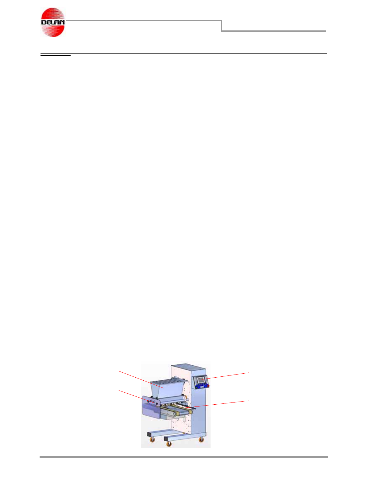
Machine composition
In this section the main parts of the machine and theIr functions withinthe production cycle
are described .
Main parts of the machine
The machine is composed of the following main parts :
a. Stainless steel hopper in which the dough is introduced
b. Control panel with screen in order to program the machine
c. Conveyor belt that transports the tray in which the dough is deposited
d.
Extruding head that contains the extruding rollers and on which the moulds and
nozzles are assembled
Fig. 1.2 Main parts of the machine
ab
c
d
page 9
02_safety_en.fm
Information on the safety features
Bisky
Chapter 2 Information on the safety features
2.1 Safety criteria
In the design and construction of this machine standards and suitable precautionary
measures were adopted to satisfy the essential safety requirements of Machine Directive
2006/42/EC, Low Voltage Directive 2006/95/EC and Electromagnetic Compatibility
Directive 2004/108/CE and its successive amendments.
The accurate analysis of the risks carried out by the manufacturer has eliminated the main
obvious risks connected to the correct operation of the machine. The complete
documentation of the standards applied to the machine to ensure its safety are contained
in a technical manual of the machine deposited by the Manufacturer.
The Manufacturer recommends the final user to carefully follow the instructions, procedures
and recommendations contained in the manual, and to observe the safety features,
hygienic, and ambient regulations and laws in the working area of the machine. The
protective mechanisms foreseen are to be integral for the entire technical life of the
machine.
DANGER Do not wear large clothes, ties, neck laces, watches which might get
entangled in the moving parts of the machine.
NOTE The Manufacturer is not responsible for injury caused to people, domestic
animals or property, due to negligence, or for disregarding the contents on
the safety features and recommendations in this manual.

page 10
02_safety_en.fm
Information on the safety features
Bisky
2.2 Personnel qualifications
NOTE The Manufacturer is not responsible for injury caused to people, domestic
animals or property, due to negligence, or for disregarding the contents on
the safety features and recommendations in this manual.
Stage of machine
technical life Qualifications of the responsible personnel
Transport The personnel transporting the machine must have read,
understood and applied the contents in:
Chapter 2 Information
on the safety features
,
2.3 Safety rules
a pag. 11 of this manual.
Installation An experienced and qualified electrician or technician that
have understood and applied the contents in:
Chapter 2
Information on the safety features
,
Chapter 3 Machine
Characteristics
,
Chapter 5 Machine programming
,
Chapter 7
Maintenance
.
Testing and fine tuning Qualified technical personnel thoroughly trained on this
specific machine, that have understood and applied the
contents in:
Chapter 2 Information on the safety features
,
Chapter 3
Machine Characteristics
,
Chapter 5 Machine programming
,
Chapter 7
Maintenance
Use Operator trained for the daily use of the machine must have
understood and applied the contents in:
Chapter 2 Information
on the safety features
,
Chapter 3 Machine Characteristics
,
Chapter 5
Machine programming
,
Chapter 7 Maintenance
.
Maintenance There are three type of maintenance personnel that can
carry out repairs on the machine:
• Mechanical maintenance personnel : Qualified
mechanical technician that is capable of carrying out
maintenance with the guards open and in normal working
conditions, capable of intervening on mechanical parts that
need adjustment, maintenance and repair. It is forbidden to
intervene electrically whilst the machine is under electrical
tension.
•Electrical maintenance personnel : Qualified electrical
technician that is capable of carrying out electrical
maintenance withthe guards open and in normal conditions,
capable of intervening on electrical parts that need
adjustment in the electrical panel even when the machine is
under tension.
• Construction technician : Qualified technician put at
disposal by the Manufacturer to carry out repairs and
maintenance of complicated nature and in particular
situations, in accordance with the owner of the machine.
Demolition Qualified mechanical technician that have understood and
applied the contents in:
Chapter 2 Information on the safety
features
.
page 11
02_safety_en.fm
Information on the safety features
Bisky
2.3 Safety rules
The following safety information specifically refers to the use of a dropping machine model
Bisky.
Before starting up the machine, the operator must be fully aware of the location and
functioning of all the commands to operate and adjust the machine.
The operator must know how to carry out the adjustments described in this manual. Make
sure that the following safety rules are read and understood. They must be observed every
day, even during maintenance operations to the machine in order to avoid injuries to the
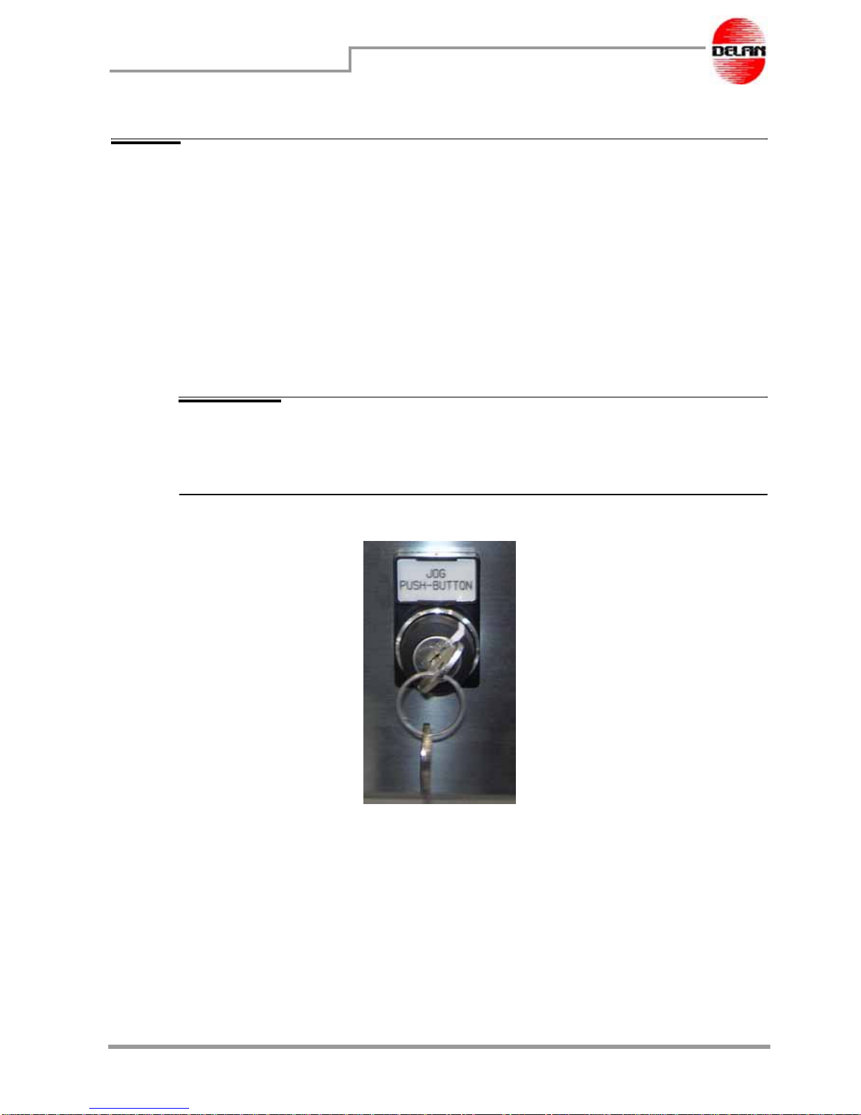
personnel and damage to the machine. The keys for the keylock switch (Fig. 2.1 Keylock
switch) for safety guards deactivation and machine start-up enabling must never be left on
the machine. They must be kept by the person in charge of the machine maintenance
operations or by the shop superintendent.
NOTE The Manufacturer cannot be held responsible for possible injuries to the
personnel in charge of machine and/or production line operation arising
from the non-observance of these safety rules and/or the tampering with the
machine and/or the production line safety devices.
Fig. 2.1 Keylock switch

page 12
02_safety_en.fm
Information on the safety features
Bisky
2.4 Protections
DEFINITION
Safety guards are all those safety measures adopted which involve the application of
specific technical mechanisms (guards, safety devices) to protect people from dangers
which cannot be neutralized completely through design.
Fixed guards
• All the fixed parts are fixed by means of bolts, screws ext. and must be unscrewed
with a tool in order to be removed
• Steel guard (A) protects against the mechanisms, the electrical/electronic
components.
Fig. 2.2 Fixed guards
NOTE The manufacturer will not be liable for injuries to persons or animals or for
damages to properties caused by the tampering with the machine safety
devices.
A

page 13
02_safety_en.fm
Information on the safety features
Bisky
2.5 Interlocking devices
DEFINITION
Emergency blocks, are switches that cause the machine to stop immediately when
activated, and do not allow the machine to start again until the emergency has been re-
activated, and the re-set button (on control panel) is pressed.
For instance, end of stroke micro-switches are considered interlocking devices because
they are used to detect when any mobile safety guard is opened. The photocells are also
considered interlocking devices. On the machine the following end of stroke micro-
switches are found and are used to stop the machine:
• a micro-switch “a” stops the machine when the steel grill (3) that cover the stainless
steel hopper is opened. The micro-switch is activated by a cam attached to the shaft on
which the grill pivots and is under the machine body;
• a micro-switch "B" stops the machine in case a tray is not found in the deposit position
above the conveyor-belts;
• a micro-switch "C" stops the machine in case the plate is extracted from its working
position;
• a photocell "D" is located at the tray infeed to stop the motion in case its reading area
was interrupted;
• two photocells "E" have been fitted at the tray outfeed to stop the motion in case their
reading is interrupted.
NOTE A side Plexiglas protection "F" has been fitted to the deposit zone and
equipped with two fastening knobs to immediately stop the machine
operation.
Fig. 2.3 End of stroke micro-switch
bd e a
cf
page 14
02_safety_en.fm
Information on the safety features
Bisky
2.6 Safety devices
DEFINITION
Active emergency systems are emergency stops assembled on the machine to prevent or
reduce the danger and injury, and are activated purposely by the operator.
1. The machine was designed with safety guards which render all its moving parts safe
and enable the operator to work under safe conditions. The Manufacturer declines
any responsibility arising from the tampering with these safety devices.
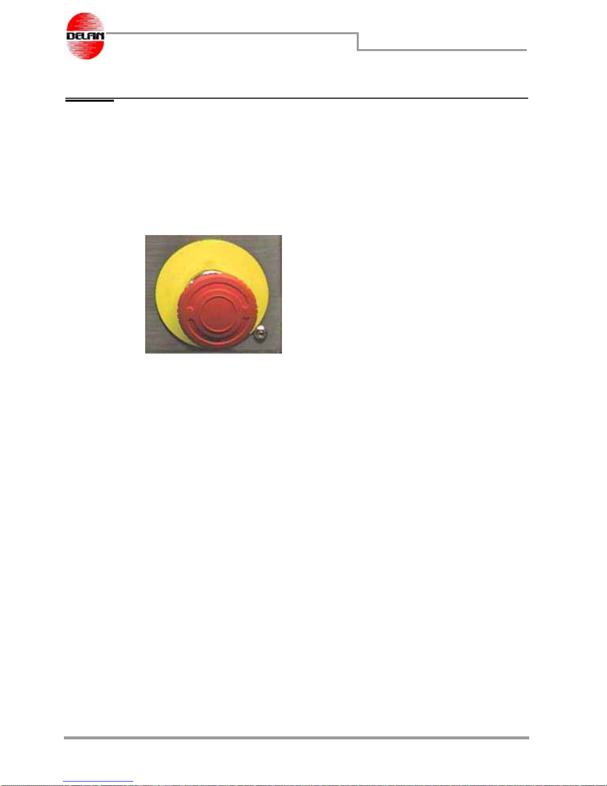
Fig. 2.4 Emergency mushroom-head button located on the control panel.
2. Some special safety systems have been installed on the machine with the purpose of
immediately stopping the machine in case of an emergency condition (
Fig. 2.4
Emergency mushroom-head button located on the control panel.
).
3. The moving guards (which can be opened through a handle) have been installed so
that when they are opened the machine stops immediately.
4. The fixed safety guards (which cannot be opened without a tool or removing some
screws) must be removed only after cutting out the electric power supply.
5. Immediately advise your superiors about any deficiency in the safety system and
guards and of any dangerous condition which occurs.
6. Under no circumstance should the safety devices be removed or tampered with.
page 15
02_safety_en.fm
Information on the safety features
Bisky
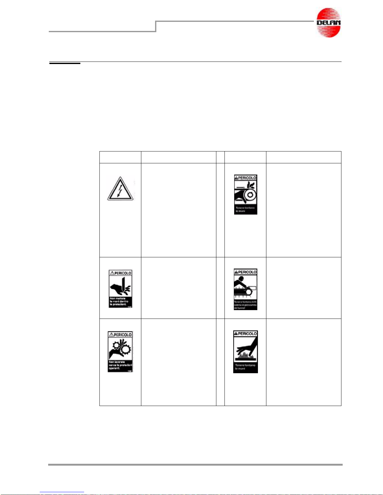
2.7 Signs illustrating the dangers on the machine
Safety labels
Safety labels are affixed in all areas where the operator - if not reminded- could be in
danger The labels are not to embellish the machine but are there to ensure the necessary
safety conditions for the operator to work in and must be understood before he operates
the machine.
LABEL MEANING LABEL MEANING
Located on the rear
guard to warn against
the presence of high
voltage inside. Be care-
ful and do not open the
safety guards without
having disconnected
the current supply
beforehand.
Located on the rear
casing to warn the
operator about the
presence inside of
driving chains, likely to
be dangerous, and
therefore it is necessary
to disconnect the
electric supply and wait
until the machine has
completely halted
before operating.
Located on the mobile
safety guard to warn
the operator that when
this guard is open, he
must keep his hands off
the moving parts
before starting operat-
ing.
Pay particular care
when the machine is
running because the
chain and the pushers
could injure your hands!
Located on the rear
casing to warn the
operator not to open
thedoorwithouthaving
cut the current supply
off and to wait until the
machine has com-
pletely stopped. This
precaution is important
in order to avoid inju-
ries to the operator's
hands.
Located on the
Plexiglassafetyguard,it
signals that the zone is
hot when the machine
is in function. Do not
touch this zone and use
gloves if operating in
this area for a long
time.

page 16
02_safety_en.fm
Information on the safety features
Bisky
Located on the rear
casing to signal that
inside the door some
dangerous electrical
connections are pres-
ent and therefore the
current supply must be
disconnected before
starting any operation.
Located next to all the
electric connector
blocks to remind the
operator to disconnect
the machine before
removing these covers.
Located on the guards
that cover any moving
parts. Before removing
these safety guards the
machine must be
turned off.
Located next to all the
safety devices which
can be removed only
with the use of tools. It
reminds the operator to
work with all the safety
guards in place and
thatbeforecarryingout
any intervention to the
machine, it must be
completely stopped.
LABEL MEANING LABEL MEANING
D_rimoz.eps
This manual suits for next models
2
Table of contents


