Delfino DRH7 User manual

Digital ORP Sensor
User Manual
Model: DRH7
Version 1.0
Daruifuno


Contents
Chapter 1 Specification......................................................................1
Chapter 2 Basic Information..............................................................2
2.1 Security Information................................................................2
2.2 Overview..................................................................................2
2.3 Dimensions.............................................................................2
Chapter 3 Installation.........................................................................3
3.1 Sensor Installation...................................................................3
3.2 Sensor Wiring............................................................................4
Ch a p te r 4 C o mm u n ic a ti o n P ro t o co l s .. . . .. . . . .. . . . .. . . .. . . .. . . . .. . . . .. . . .. .. . . . 5
4.1 Overview of Modbus RTU.........................................................9
4.2 Corresponding parameter table of communication address ..........................10
4 . 3 H o w t o u s e c o m m o n f u n c t i o n s . . . . . . . . . . . . . . . . . . . . . . . . . . . 1 2
4.3.1 Reading electrode measurements....................................................12
4.3.2 Modify electrode address....................................................12
4.3.3 Electrode calibration....................................................12
4 . 3 . 4 F a c t o r y r e s e t . . . . . . . . . . . . . . . . . . . . . . . . . . . . . . . . . . . . . . . . . . . . . . . . . . . . 1 3
Chapter 5 Maintenance and Care........................................................ 14
5. 1 Ma i n te n a n c e i n te r v a l .. . . . .. . . . . . . .. . . .. . . . . .. . . . . . .. . . . . .. . . . . . . . .. . .. . . . . . . 14
5.2 Common problems and solutions ........................................................14


Basic Information
1
Measuring range
-2000 ~ +2000 mV
0.0~50.0 °C
Resolution
1 mV 0.1 °C
Accuracy
±2 mV
Calibration method
Zero calibration, slope calibration, deviation calibration
Operating temperature
0 to 50°C
Work pressure
≤2Bar
Waterproof level
IP68
Power requirements
9~36VDC
Power consumption
About 0.2W
Electrical isolation
Power and communication are isolated inside the sensor
Communication Interface
RS485 MODBUS
Shell material
ABS
Shell size
Diameter 35mm, total length about 260mm (including
cleaning protective cover)
Installation size
One imperial 1" NPT thread on each end
Insertion depth 100mm (including cleaning connector
115mm)
weight
About 150 grams (without cable)
Cable
PUR (polyurethane) sheath, standard 10 meters, custom
lengths available
Connection method
Bare wire, M12 plug or waterproof aviation plug
Chapter 1 Specification
Product specifications are subject to change without notice.
Basic Information
2
Chapter 2 Basic Information
2.1 Security Information
Please read this manual completely before unpacking, installing and operating this
equipment. Pay special attention to all precautions. Otherwise, it may cause serious
personal injury to the operator or damage the equipment.
2.2 Overview
The digital ORP sensor adopts the classic electrochemical principle, which is reliable in
measurement and stable in performance. Widely used in environmental protection water
treatment, surface water, purified water, circulating water and other systems, as well as
electroplating, electronics, printing and dyeing, chemical, food, pharmaceutical and other
process fields. Excellent performance in sewage treatment, drinking water treatment,
surface water monitoring, pollution source monitoring, industrial process and other
applications.
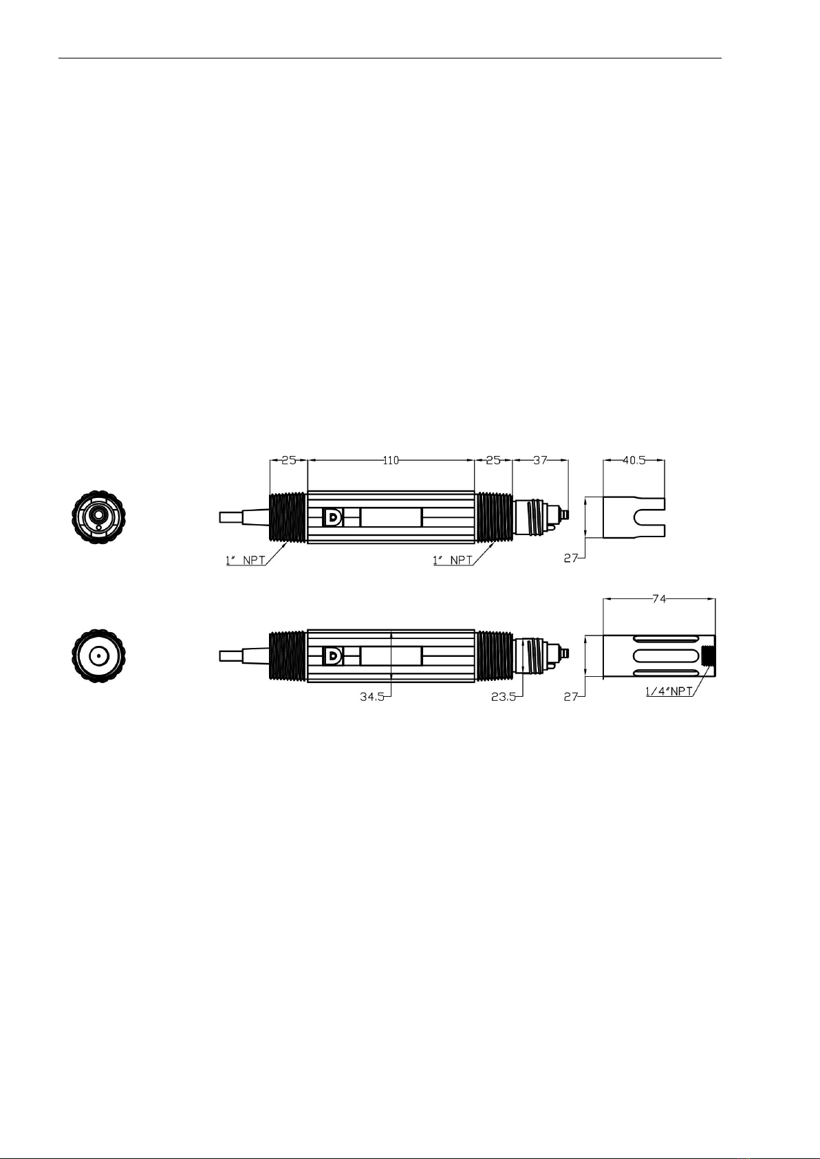
2.3 Dimensions
Figure 1 Dimensions of the sensor

Installation
3
1-DN60 U-shaped card
7-M4 screw nut 8*4
2-U-shaped board
8-“8”shaped clip 25&32
3-Handle sleeve
9-M4 screw*25*2
4-DN40 U-shaped card
10-handle
5-M6 screw nut*8
11-DN32PVC Bracket
6-Rainproof elbow
12-1 inch inner wire straight pipe joint
Chapter 3 Installation
3.1 Sensor Installation
Refer to the pictures in this section to install and fix the sensor. To ensure that the sensor can
measure safely and accurately, the following conditions must be met during installation:
Choose a location that is convenient for operation and maintenance to install the sensor.
The ORP sensor needs regular maintenance;
The electrode installation angle is within ±30°, and the electrode cannot be installed
horizontally or upside down;
Do not remove the protective cap when installing the electrode on site, and then remove
the protective cap after the installation is over.
Figure 2 Schematic diagram of railing installation
Installation
4
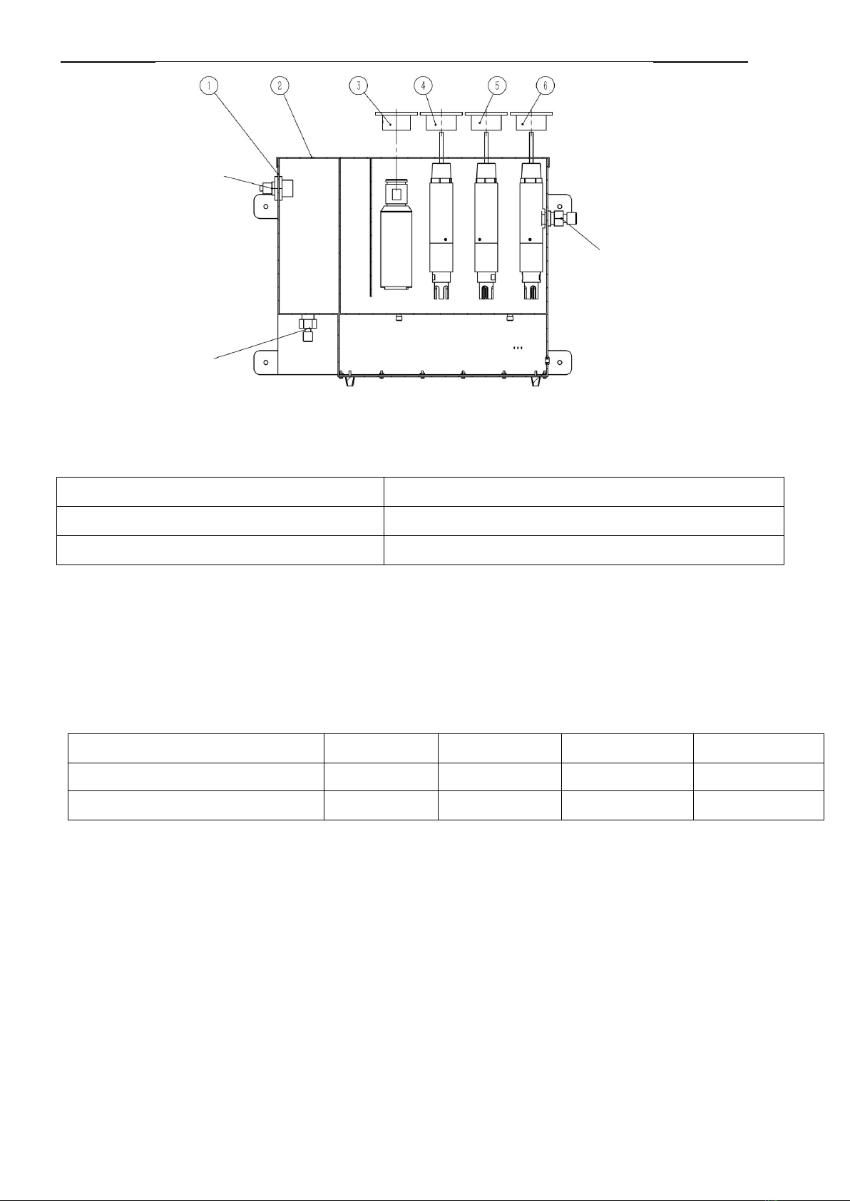
The sensors are connected correctly as defined in the table below.
Note: Aviation plug version does not require user to connect wires.
1-Flow cell
4-pH sensor fixed connection cover
2-Flow cell cover
5-dissolved oxygen sensor fixed connection cover
3-Turbidity sensor fixed connection cover
6-conductivity sensor fixed connection cover
Wire Color
red
black
white
green
Terminal Definition
Power positive
Power negative
RS485 data A (+)
RS485 data B (-)
Instrument Terminal Symbols
V+
V-
AS
BS
Water overflow
water intake
Water outlet
Figure 3 Schematic diagram of five-parameter flow cell installation
3.2 Sensor Wiring

Protocol
5
About Modbus RTU overview:
The electrode acts as a slave on the network and supports the Modbus RTU
communication protocol.
Data communication is initiated by the host, and the first byte of the transmitted message
is the target slave address. After the first byte is received by all the slaves on the network,
each slave will decode it to determine whether the message is sent to itself.
The transmission of the RTU message frame shall start with a pause interval of at least
3.5 character time. After the transmission of the last character, a pause of at least 3.5
characters time marks the end of the message frame. A new message can start after this
pause. During transmission, the entire message frame must be transmitted in a
continuous stream. If there is a pause interval of more than 1.5 character time before the
transmission of the message frame is completed, the receiving device will flush the
incomplete message and assume that the next byte is the start of a new message.
Likewise, if a new message begins with the previous frame within less than 3.5
characters, the receiving device will consider it a continuation of the previous frame, and
this will result in an error because the final CRC The value cannot be correct.
The host can send command frames to read individual or all data results.
The data frame format is as follows (all data are in Hex format)
Host sends:
1
2
3
4
5
6
7
8
slave
address
function
code
Register start
address upper
8 bits
Register
start
address
lower 8 bits
The upper
8 bits of the
number of
registers
The lower 8
bits of the
number of
registers
CRC
lower 8
bits
CRC
high 8
bits
The slave responds:
1
2
3
4
5
5+n
5+n+1
5+n+2
5+n+3
slave
address
function
code
Data
bytes
Data 1
high 8
bits
Data 1
lower 8
bits
Data n
high 8
bits
Data n
lower 8
bits
CRC
lower 8
bits
CRC
high 8
bits
Chapter 4 Communication
4.1 About Modbus RTU Overview
Protocol
6
Example:
Send frame: [01 04 00 02 00 02 D0 0B], meaning as follows:
[01]: slave address
[04]: function code
[00 02]: The starting address of the register is 0x02
[00 02]: Read 2 registers from the starting address (ie, read 1 single-precision floating-point
data result)
[D0 0B]: CRC check data
Return frame: [01 04 04 00 00 41 C8 CA 42], meaning as follows:
[01]: slave address
[04]: function code
[04]: The number of bytes returned is 4
[00 00 41 C8]: 41 C8 00 00 (that is, the floating-point value is 25, the specific value meaning
is to find the corresponding address)
(Note: Combine two 16-bit integer registers to form a single-precision floating-point number,
pay attention to the order of the data)
4.2 Corresponding parameter table of communication address
Main measurement (read with function code 04)
Parameter
Address
Data Format
Value Range
Initial Value
Illustrate
Main measured value
2
32 Bit Float
-2000~+2000
-
Unit: mV
Temp. measurement
4
32 Bit Float
0~50
-
Unit: Celsius
Communication parameters (read with function code 03, write with function code 06)
Parameter
Address
Data Format
Value range
Initial Value
Illustrate
Address
0
Unsigned
1~254
9
-
Baud rate
1
Unsigned
0~3
1
0:4800
1:9600
2:19200
3:38400
Check Digit
2
Unsigned
0~2
0
0: no verification
1: Even parity
2: odd parity
Stop bit
3
Unsigned
1~2
1
1:1 bit
2: 2 bits

Protocol
7
System setting parameters (read with function code 03, write with function code 06)
Parameter
Address
Data Format
Value range
Initial Value
Illustrate
Sample rate
4
Unsigned
0~4
2
0: Level 2 buffering
1: Level 4 buffering
2: 8-level buffer
3: 16-level buffer
4: 32-level buffer
Temperature
mode
5
Unsigned
0~1
0
0: Automatic
1: Manual
User setting parameters (use function code 03 to read, function code 16 to write)
Parameter
Address
Data Format
Value range
Initial
Value
Illustrate
Slope calibration
point calibration
value
100
32 Bit Float
-
256
The calibration point
value can be changed,
the default is 256mV
Zero calibration
point standard
liquid value
102
32 Bit Float
-
86
The calibration point
value can be changed,
the default is 86mV
zero
106
32 Bit Float
-
0
The value is generated
according to the user
calibration, the zero value
can be changed
Slope
108
32 Bit Float
-
1
The value is generated
according to the user
calibration, the slope
value can be changed
Main measurement
offset
112
32 Bit Float
-2000~+2000
0
The main measurement
offset value can be
changed, the setting
range is between -2000
and +2000
Temperature offset
114
32 Bit Float
-100~100
0
The temperature offset
value can be changed,
the setting range is
between -100 and 100
Manual
temperature value
116
32 Bit Float
0~100
25
Manual temperature
value can be changed,
the setting range is
between 0 and 100
User calibration parameters (read with function code 03, write with function code 16)
Parameter
Address
Data Format
Value range
Initial
Value
Illustrate
Slope
calibration
200
32 Bit Float
-
-
Write the value 256 for
slope calibration
Zero calibration
206
32 Bit Float
-
-
Write the value 86 for
zero calibration

Protocol
8
Recovery (Write with function code 06)
Parameter
Address
Data Format
Value range
Initial
Value
Illustrate
Restore settings
400
Unsigned
-
-
Write the value of 99 to
restore the setting
parameters, but the
communication settings
will not be restored
Read the ORP value and temperature value measured by the electrode (assuming the
electrode address is 1)
Host sends [01 04 00 02 00 04 50 09]
[01] Indicates the electrode address, where the electrode address is 1
[04] Indicates the function code, here use the function code 04 to read the measured value
[00 02] represents the starting register address, where the starting register address is 2
[00 04] indicates the number of registers to be read, here 4 registers are read
[50 09] Indicates CRC check code
Electrode return data [01 04 08 00 00 40 E0 00 00 41 C8 9A DD]
[01] Indicates the electrode address, where the electrode address is 1
[04] Indicates the function code, here use the function code 04 to read the measured value
[08] Indicates the number of data bytes, there are 8 bytes here
[00 00 40 E0] These 4 bytes represent the ORP value, the value is represented by a
floating point number, [00 00] is the lower 16 bits, [40 E0] is the upper 16 bits, that is, the
32-bit floating point number is [40 E0 00 00 ], after converting to decimal, it is 7, and the mV
value is 7
[00 00 41 C8] These 4 bytes represent the temperature value, the value is represented by a
floating point number, [00 00] is the lower 16 bits, [41 C8] is the upper 16 bits, that is, the
32-bit floating point number is [41 C8 00 00 ], converted to decimal number is 25, the
temperature value is 25 degrees Celsius
[9A DD] means CRC check code
Modify the electrode address, change the electrode address from 1 to 2
Host sends [01 06 00 00 00 02 08 0B]
4.3 How to use common functions
4.3.1 Reading electrode measurements
4.3.2 Modify electrode address

Protocol
9
Electrode calibration (assuming the electrode address is 1)
Zero calibration:
The calibration value is the value set by the zero calibration point, the default is 86
Use function code 16 to write value 86 to register address 206 to perform calibration
Host send [01 10 00 CE 00 02 04 00 00 42 AC 4E AE]
Slope calibration:
The calibration value is the value set by the slope point, the default is 256
Use function code 16 to write value 256 to register address 200 to perform calibration
Host send [01 10 00 C8 00 02 04 00 00 43 80 CE C9]
Factory reset (communication parameters are not restored) (assuming the electrode address is 1)
Use function code 06 to write the value 99 to the register address 400 to perform recovery
Host sends [01 06 01 90 00 63 C8 32]
4.3.3 Electrode Calibration
4.3.4 Factory reset
Maintenance
10
In order to obtain the best measurement results, regular maintenance
and maintenance are required. Maintenance and maintenance include
cleaning of electrodes, checking for damage, etc.
Maintenance work
Maintenance frequency
Visual inspection
per month
Check Calibration
Monthly (depending on usage environment conditions)
Replace electrodes
Yearly (according to usage environment conditions)
Phenomenon
Approach
Electrodes cannot
communicate
1. Check whether the electrode wiring is correct
2. Check the communication setting parameters (address,
baud rate, parity bit, stop bit)
The measured
value is not normal
1. Check whether the electrode platinum ring is clean and
whether the sensor is damaged
2. Restore the electrode to the factory calibration value,
clean and re-calibrate with standard buffer
3. Check the service life of the electrode
Chapter 5 Maintenance
5.1 Maintenance Period
5.2 Common problems and solutions


Table of contents


 owner's manual")


