Deliverance MJH-A1 User manual

1
MJH‐A1ManualFeb26,2021
Operator’sManual:DeliveranceMiniJackHammerModelMJH‐A1 106273
Seepages11and12

2
TableofContents
SafetyInformation……………………………………………………..…………..Page3
ProductSpecifications…………………………………………………..……..…Page4
OperatingInstructions…………………………………………………..………..Pages5&6
Maintenance&Troubleshooting…………………………………………..…Page7,8&9
ExplodedView,QuickChangeHammerHeads&PartsList……….Pages10,11&12
MJH‐A1ManualFeb26,2021

3
TO AVOID SEVERE PERSONAL INJURY OR PROPERTY DAMAGE
BEFORE OPERATING THIS TOOL, ALL OPERATORS SHOULD READ AND STUDY THIS MANUALTOUNDERSTANDAND
FOLLOW THE SAFETY WARNINGS AND INSTRUCTIONS. FAILURE TO FOLLOW WARNINGS COULD RESULT IN DEATH OR
SERIOUS INJURY. KEEP THESE INSTRUCTIONS WITH THE TOOL FOR FUTURE REFERENCE.
SAFETY INSTRUCTIONS:
EYE PROTECTION which conforms to ANSI/ CE specifications and provides protection against flying particles both from the
FRONT and SIDE should ALWAYS be worn by the operator and others in the work area when connecting to air supply,
loading, operating or servicing this tool. Eye protection is required to guard against flying fasteners and debris, which
could cause severe eye injury.
The employer and/or user must ensure that proper eye protection is worn. Eye protection equipment must conform to
the requirements of the ANSI Z87.1 and 89/686/EEC, and provide both frontal and side protection. NOTE: Non‐side
shielded spectacles and face shields alone do not provide adequate protection.
CAUTION: Additional Safety Protection will be required in some environments. For example, the working area may include
exposure to noise level which can lead to hearing damage. The employer and user must ensure that any necessary hearing
protectionisprovidedandusedbytheoperatorandothersintheworkarea.Some environments will require the use of head
protection equipment. When required, the employer and user must ensure that head protection conforming to ANSI Z89.1/ CE is
used.
AIR SUPPLY AND CONNECTIONS
Do not use oxygen, combustible gases, or bottled gases as a power source for this tool as tool may explode possibly
causing injury.
Do not use supply sources which can potentially exceed 200 PSI (14 kg/cm2) as tool may burst, possibly causing injury.
SAFETY INSTRUCTIONS
Alwayswearbreathingprotectionduetoparticlesthatcouldbecomesuspendedintotheair.
Alwaysoperatethetoolinasafemannerandbecarefulforthesafetyofothersintheworkareaaroundyou.
Alwayskeepthetoolproperlymaintained.
Alwayskeephandsawayfrommovingparts.
Alwaysholdthetoolawayfromclothingandhairtoavoidthepossibilityofbecomingentangled.
Alwayskeeptoolawayfromanyelectricalsourcetoavoidelectricshockbeingtransmittedthroughthetool’saluminum
housingoranyotherportionofthetoolorit’sattachments.
Neverleavethetoolconnectedtotheaircompressorwhennotinuse.
Neveroperatethetoolnearflammablesubstances.
OnlyuseRepairPartsandAttachmentsrecommendedbythemanufacturerofthistool.
MJH‐A1ManualFeb26,2021

44
209.77mm(8.26”)
173.43mm(6.83”)
51.00mm(2.00”) Length:209.77mm(8.26”)
Height:173.43mm(6.83”)
Width:51.00mm(2.00”)
Weight:4.30lbs
ChiselShankDiameter:.401”
ToolBitRetention:QuickConnect
BoreSize:20.68mm(.814”)
StrokeLength:44.00mm(1.73”)
BlowsperSecond:37
AdjustableSpeedControl
AirInletThread:1/4‐18NPT
SwivelAirConnector
AirHose:3/8”
WorkingPressure:90PSI(atthetool’sInlet)
PRODUCTSPECIFICATIONS
MJH‐A1ManualFeb26,2021

5
NailGuide
Instructions:HowToLoadaQuickChangeHammerHeadintotheTool
ProcessingToolwithadapterfor
Chiseling/Scraping/Hammering
FencingStapleGuide
ForstandardProcessingTools,insertadapterontoshank
beforeinsertingtheQuickChangeHammerHead Adapter
PullbackSpring
LoadedCollar
1
2
InsertQuick
Change
Hammer
Head
ReleaseSpring
LoadedCollar
3
MJH‐A1ManualFeb26,2021

6
Instructions:HowtoOperatetheToolwithQuickChangeHammerHeads
Setthecompressoroutputregulatortoapressurethatwillcreate90PSIattheendofthehosethatthetoolwillbeconnected to.
Pleasereadalloftheinstructionsandwarningscarefullybeforeoperatingthetool.
3
worksurface
4
Pullthetrigger
5Pushtooltoward
worksurface
Positionthe
toolsothat
theFastener
pointortipof
Processing
Toolisagainst
thework
surface
2
ForNail&Staple
Guides,Muzzle
LoadFastenerinto
Guide.For
ProcessingTools,
skipthisstep
Fastener
Guide
Fastener
1
MJH‐A1ManualFeb26,2021

7
Maintenance,TroubleShooting
Care&Maintenance
1) Alwaysremovethetoolfromtheairsupply
beforeperforminganymaintenanceonthe
tool.
2) Tokeepthetoolproperlylubricated,addtwo
orthreedropsofAir‐ToolOildailyintotheair
inletfitting.Iftoolisusedheavily,addmore
dropsperday.
3) Ifthetoolistobestoredforanextended
periodoftime,lightlylubricatethetooland
brieflyoperatethetooltoinsurethattheoil
hasbeendistributedthroughoutthetool.
Storethetoolinaclean,drylocation,outof
thereachofchildren.
IfToolRunsSlowlyorwillnotoperate
1) Ifthereisgritorguminthetool,flushthetoolwithair‐tool
oilorgumsolvent.
2) Ifthereisnooilinthetool,addtwoorthreedropsofair‐
tooloilintotheairinletfittingandthenbrieflyoperatethe
tooltodistributetheoilthroughoutthetool.
3) Ifairleaksfromtheinletfitting,disconnectthetoolfromthe
airsupply,removeinletfitting,addthreadsealanttapeonto
thethreadsofthefittingandthenre‐installinletfitting.
4) Ifmoistureisobservedsprayingfromtheairtoolexhaust,
waterislikelyinsidetheaircompressortank.Disconnectair
toolfromhose.Unplugcompressorfromelectricalsupply.
Releaseairpressurefromthecompressortankanddrain
waterfromtheaircompressortank.
5) Sinceairpressuredropsthroughthehose,useapressure
gageatthetoolendofthehoseandsetthecompressor
outletregulatortoapressuresettingthatwillproduce90PSI
atthetoolendofthehose.
Addtwoorthreedropsof
OilDailyintoAirFittingInlet
MJH‐A1ManualFeb26,2021

8
QuickConnect
Coupler
Procedure to re-align the Quick Connect Coupler on the MJH-A1 Tool
IftheNailGuidesand/orotherQuickChangeHammerHeadsbecomedifficulttoinsertandremove
fromthetool,theQuickConnectCouplermayneedtobere‐alignedasdescribedbelow.
Step 1: Remove the three set screws from the Quick Connect Coupler.
Step 2: Slightly loosen the Quick Connect Coupler by unscrewing it slightly.
Step 3: Install a Universal Nail Guide into the coupler to insure a proper alignment of the
Coupler versus the cylinder bore.
Step 4: Re-tighten the Coupler by hand just snug, not too tight.
Step 5: Add medium strength Loctite #243 onto all three set screws.
Step 6: Install all three set screws to almost tight, then backed off slightly to avoid
causing a misalignment of the coupler versus the cylinder.
Step 7: Tighten all three set screws evenly.
ThreeSetScrews
UniversalNailGuideDPSH‐2010
MJH‐A1ManualFeb26,2021

9
Ifthemagnetsneedtobereplaced,followthisprocedure
TofurthersecuretheMagnetsinplace,addalayer
ofepoxyallaroundontopofthemagnetsalso
AddEpoxyallaround
circumferenceofthe
holes,thenInsert
DPSH‐1387Magnets SlightlyliftupontheendoftheHeatShrink
Tubingtohelpliftitoutoftherecessed
diameter,thenSlidetheHeatShrinkTubingto
exposethemagnetholes
1
2
Note:IfneedtoreplacetheHeatShrink
Tubing,seechartbelowshowingreplacement
partnumbersforeachofthefourNailGuides
3
4
SlidetheHeatShrinkTubingbackoverthemagnetholes
MJH‐A1ManualFeb26,2021

10
PartsExplodedView&PartsList
18
19
20
9
810 11 12 13 14 10
15
16
17
Shownon
Page11
Shownon
Page12
Note:Item34DPSH‐1930
Adapterisasub‐assembly
containingAdapterDPSH‐1867
andInternalO‐ringDPSH‐1869
MJH‐A1ManualFeb26,2021

11
DPSH‐2000SpikeNailGuide
DPSH‐20601‐1/2”NailGuidefor7/16”NailHeads
DPSH‐2030FenceStapleGuide
(.500”OutsideCrownx.131”StraightLeg)
DPSH‐2050FenceStapleGuide
(.700”OutsideCrownx.164”StraightLeg)
DPSH‐2010Universal(2‐1/2”)NailGuide
DPSH‐20201‐1/2”JoistHangerNailGuide
DPSH‐1720De‐Nailer
DPSH‐1725FlooringDe‐Stapler
DPSH‐1735FencingDe‐Stapler
24
22
23
21
25
26
27
28
29
MJH‐A1ManualFeb26,2021
NailGuidesandHammerHeads
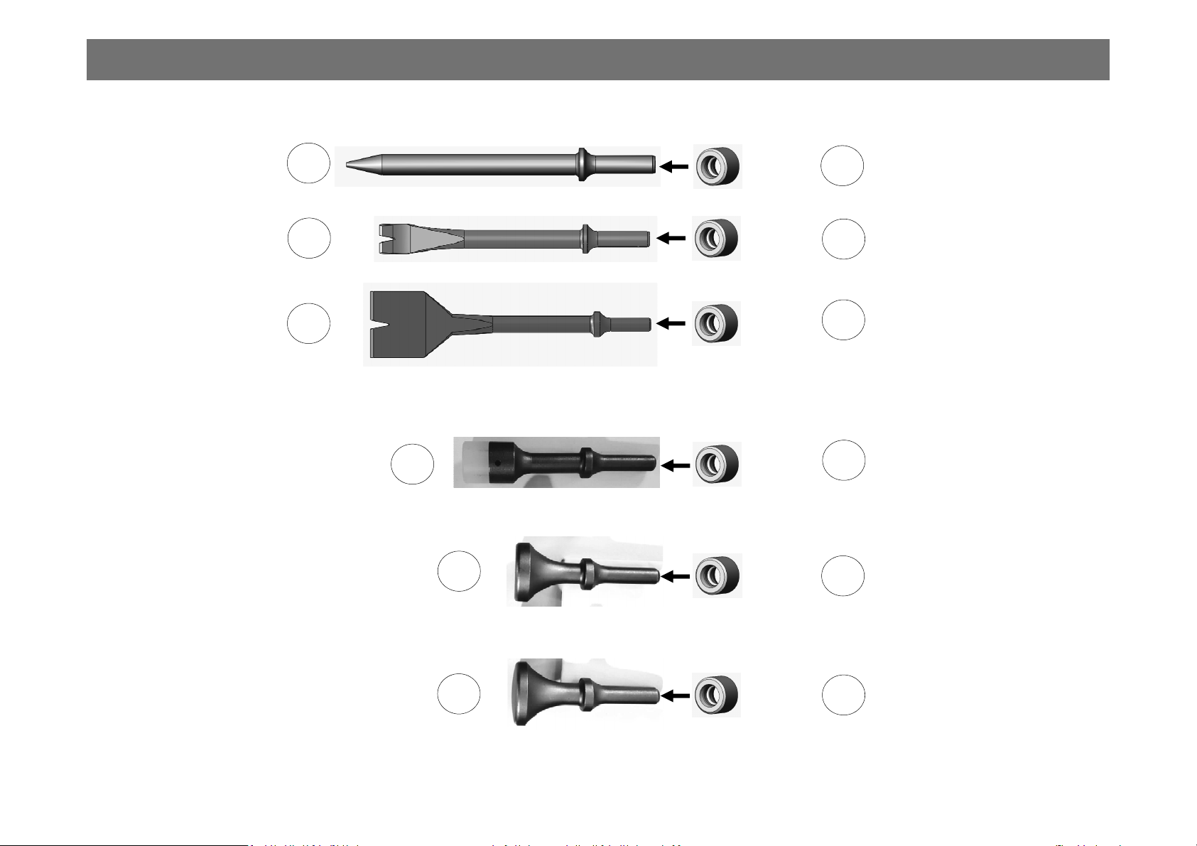
12
DPSH‐1930
DPSH‐1900PoundingHammerwith
35mmDiameterFlatSteelFace
Adapter
Adapter
DPSH‐1930
DPSH‐17363/4”WideUn‐Nailer Chisel
DPSH‐1593ConicalChipper
DPSH‐19282”WideUn‐Nailer Scraper
DPSH‐1930
Adapter
DPSH‐1905PoundingHammerwith
35mmDiameterConvexSteelFace
DPSH‐2015PoundingHammerwith25mm
DiameterReplaceablePolyurethaneFace
DPSH‐2015
DPSH‐1905
DPSH‐1900
DPSH‐1930
Adapter
Adapter
DPSH‐1930
DPSH‐1930
Adapter
33
31
32
30
34
35
36
36
36
36
36
36
MJH‐A1ManualFeb26,2021
Table of contents
Popular Tools manuals by other brands


Klein Tools
Klein Tools STP100 instructions

AHB
AHB SUGINO Barriquan BC10-20 instruction manual

Drieaz
Drieaz Rescue Mat F286 owner's manual

Central Pneumatic
Central Pneumatic 61244 Owner's manual & safety instructions

FLORABEST
FLORABEST FSG 85 D1 Translation of the original instructions
ICON
ICON A5 2021 Service bulletin

Traditional Tool Repair
Traditional Tool Repair DSA-116 Operation, parts and safety manual

Reelcraft Industries, Inc.
Reelcraft Industries, Inc. RT635-OMP operating instructions

Equalizer
Equalizer FA4TM Operator's instruction manual

Band-it
Band-it GRC002 operating instructions

Delta
Delta 36-850 instruction manual

sunjoe
sunjoe 24V-AGR100 manual