Delixi CJX2 Series User manual

CJX2 Series AC Contactor
User Manual
Please carefully read this User Manual before installing
and operating the product, and keep this manual properly
for future reference

Safety Notice
Please carefully read this instruction before the installation, operation, run, maintenance, and inspection, and
follow the contents of the instruction to properly install and operate this product.
Danger:
⚫Do not operate the contactor with your wet hands;
⚫Do not touch the energized parts during operation;
⚫Mark sure that the product is de-energized during the maintenance and service;
Caution:
⚫The installation, maintenance and service shall be performed by the qualified professional;
⚫Please confirm that the product voltage, current, frequency and utilization category of the product
meet the operating requirements before use;
⚫Please connect the control circuit first, carry out the no-load operation test, and then connect the load if
there is no abnormality;
⚫Please tighten the terminals regularly and remove the deposited dust;
⚫Do not let foreign objects fall into the product;
⚫If you need to purchase accessories, please choose the matching accessories provided by our company;
⚫If found damage or abnormal sound when unpacking, please stop the operation immediately and contact
the supplier;
⚫When scrapping the product, please dispose the product waste properly. Thanks for your cooperation;

About CJX2-9~95 AC Contactor
● Panel Introduction (Figure 1 Product Diagram)
Legends:
1-Main circuit outlet 2/T1, 4/T2, 6/T3
2-Product model
3-Main circuit inlet 1/L1, 3/L2, 5/L3
4-Coil inlet terminal A1
5, 10-Coil outlet terminal A2
6-NC auxiliary inlet terminal 21/NC
7-NO auxiliary inlet terminal 13/NO
8-NO auxiliary outlet terminal 14/NO
9-NC auxiliary outlet terminal 22/NC
11-Company trademark
12-Product model
13-Certification mark
14-Standard GB/T 14048.4, IEC 60947-4-1
15-Agreed free air heating current
16-Insulation voltage Ui: 690V
17-Utilization category: AC-3, mechanical interlock
N: AC4
18-Ue, Ie and Pe under use category
19-Company name

● Technical Parameters
Table l Technical Parameters

Normal Operation, Installation and Transport Conditions
●Normal Operation and Installation Conditions
(1) The ambient air temperature is not higher than +40℃, and is not below -5℃, and the average value within 24
hours does not exceed +35℃;
(2) The altitude of the installation site does not exceed 2000m;
(3) Atmospheric conditions
The relative humidity of the atmosphere does not exceed 50% when the highest ambient temperature is +40℃, and
a higher relative humidity is allowed at lower temperatures, such as 90% at 20℃. Protective measures shall be
taken for condensation occasionally occurred due to temperature changes.
(4) The installation position shall be vertical, and the inclination angle at each direction shall not exceed ±5°;
(5) Installed at a place where there is no impact, vibration, and rain or snow erosion;
(6) Pollution level: Level 3;
(7) Installation category: Class III;
(8) Rated impact withstand voltage Uimp:8000V;
(9) Rated frequency :50Hz:
(10) Protection grade: IP20:
(11) Suitable for 8h working system, intermittent cycle working system, uninterrupted working system and short-
time working system.
●Normal Storage and Transport Conditions
(1) Temperature: -25oC~+55℃, +70oC in a short time (24h);
(2) Relative humidity : ≤95%;
(3) During the transport, please handle the product gently, and do not upside it down, and prevent the product
from harsh collision;
(4) The product shall not be attacked by rain or snow during transportation and storage.

Installation Products
● The contactor has two installation methods: screw installation and rail installation. CJX2-9~32 can be installed
with 35mm standard rail, and CJX2-40~95 can be installed with 35mm or 75mm standard rail.
● See Figure 2, Figure 3 and Table 2 for Outline and Installation Dimensions.
Fig. 2 CJX2-9~32 Fig. 3 CJX2-40~95
Table2 CJX2-9~95 AC Contactor Outline and Installation Dimensions Unit: mm

● Outline and installation dimensions of the reversible AC contactor are shown in Figure 4, Figure 5 and Table 3
Figure 4 CJX2-9N~32N
Figure 5 CJX2-40N~95N
Table 3 CJX2-9N~95N reversible AC Contactor Outline and Installation Dimensions
Unit: mm
● Accessories installation
(1) Auxiliary contact
The CJX2-9~32 contactor main body has 2 NO or 2 NC auxiliary contact groups, and the CJX2-40~95
contactor main body has 2NO + 2NC auxiliary contact groups, its main parameters are shown in Table 4;
Table 4 Main parameters of auxiliary contact
Utilization
category
Rated
insulation
voltage Ui
Conventional free air
heating current Ith
Control capacity Rated operating current Ie
Make Break 220V 380V
AC-15
690V 10A
3600VA 360VA 1.6A 0.95A
DC-13 33W 0.15A -
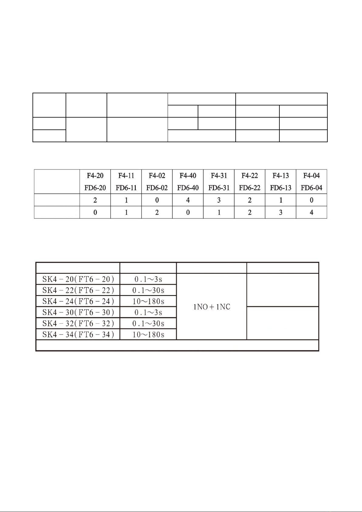
The contactor can be equipped with an independent auxiliary contact module. Its model specification and
combination of NO and NC are shown in Table 5.
(2) Air delay head (Pneumatic timer)
The contactor can be combined with SK4 (or FT6) air delay head to form a delay contactor. The delay range
is shown in Table 6.
Table 6 Air delay head
(3) Electromagnetic starter
The contactor can be installed and combined with JRSID series thermal overload relay to form an
electromagnetic starter.
NC
NO
Model
Power-on delay
Power-off delay
Model
Time Range
Contact
Delay type
Note: The air delay head is adjusted to the minimum value when delivery.

Debugging, operation
● Check whether the technical parameters of the product meet the requirements for use;
● Connect the control circuit first, conduct a no-load operation test, and then connect the load if there is no
abnormality;
● Do not let foreign objects fall into the product;
● It is recommended to select SCPD according to type 2 coordinated protection, and its fuse type is shown in
Table 7.
Table 7 Matching fuse model
● Wiring capacity and tightening torque are shown in Table 8
Table 8 Wiring capacity and tightening torque
Maintenance
● The contactor should be tightened regularly, remove the deposited dust and other operations, otherwise there will
be a risk of fire and short circuit;
● The small metal particles splashed around the contacts of the contactor or on the arc cover should be removed,
and the contact surface should be stopped when the surface of the contact is burned to expose the base material.
Fault Analysis and Treatment
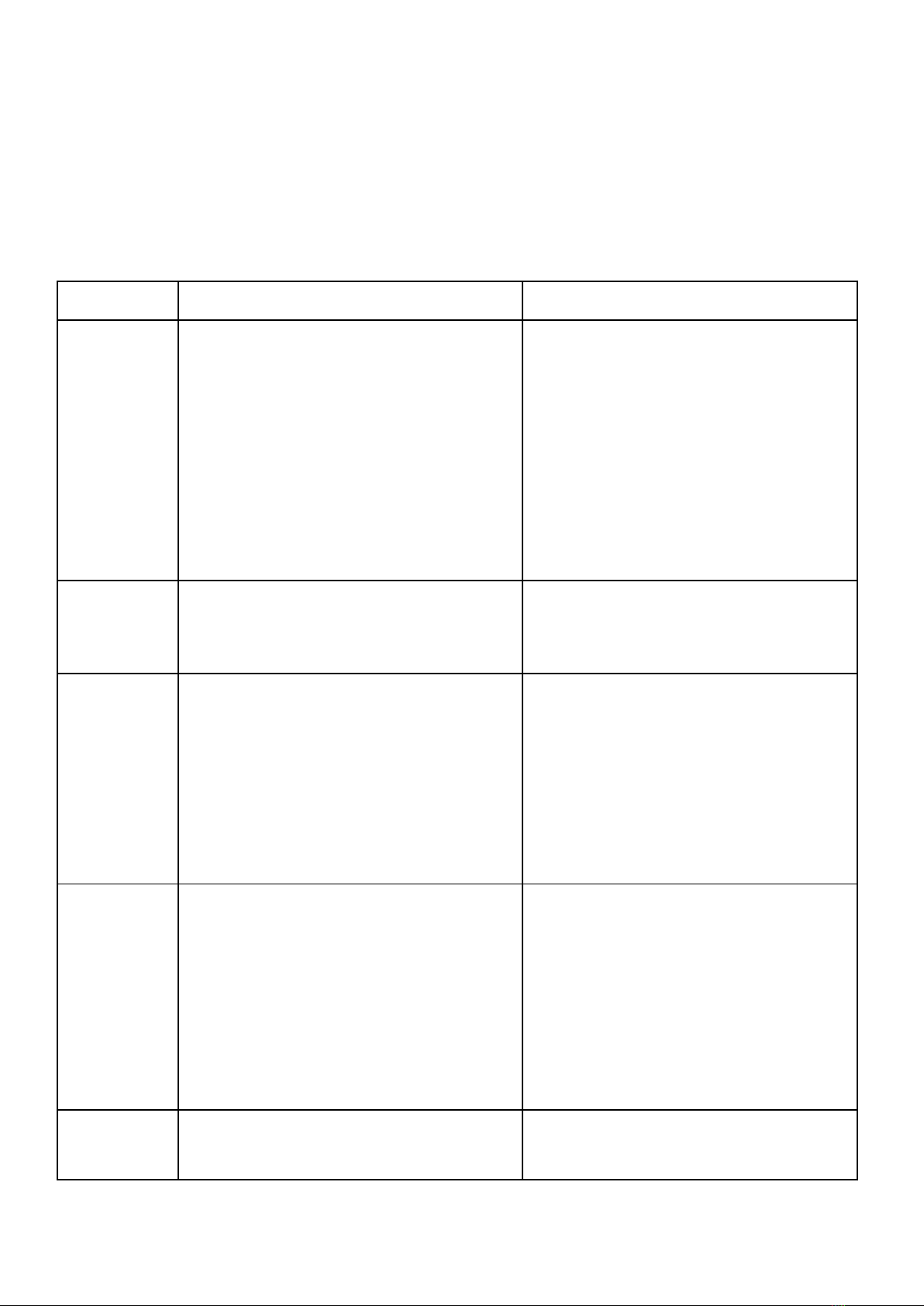
See Table 9 for common fault analysis and handling.
Table 9 Analysis and treatment of common faults
Fault Cause Analysis Treatment measures
The iron core
cannot be closed
or the suction
force is
insufficient (that
is, the contact
has been closed
but the iron core
has not been
fully attracted)
1. The power supply voltage is too low or
fluctuates too much;
2. The power supply capacity of the operating
circuit is insufficient or disconnection, wiring
errors and poor contact of the control contacts;
3. The technical parameters of the coil do not
match the conditions of use;
4. The product itself is damaged ( Such as coil
disconnection or burnout, mechanical movable
parts stuck, etc.)
1. Increase the power supply voltage;
2. Increase the power supply capacity, replace
the circuit, and repair the control contacts;
3. Replace the contactor;
4. Eliminate stuck faults and repair damaged
parts.
no release or
slow release
1. The contact is welded;
2. The movable part of the machine is stuck;
3. There is oil or dust on the pole surface of the
iron core.
1. Eliminate welding faults, repair or replace
the contactor;
2. Eliminate stuck faults;
3. Clean the pole surface of the iron core.
Coil overheating
or burning out
1. The power supply voltage is too high or too
low;
2. The technical parameters of the coil (such as
rated voltage, frequency, energization duration
and applicable working system, etc.) do not
match the actual use;
3. The moving part is stuck;
4. The pole surface of the iron core is uneven or
dust sticking.
1. Adjust the power supply voltage;
2. Replace the contactor;
3. Eliminate mechanical jamming;
4. Clear the pole surface.
Electromagnet
(AC) is noisy
1. The power supply voltage is too low;
2. The magnetic system is skewed or
mechanically stuck, so that the iron core cannot
be sucked flat;
3. The pole surface of the iron core is rusted or
foreign matter invades the pole surface of the
iron core;
4. The short-circuit ring is broken or the pole of
the iron core is broken. The surface is
excessively worn and uneven.
1. Increase the voltage of the operating circuit;
2. Adjust the magnetic system or eliminate
mechanical jamming;
3. Clean the pole surface;
4. Replace the contactor.
Contact welding
1. The operating frequency is too high or the
product is overloaded;
2. The load side is short-circuited;
1. Replace the appropriate contactor;
2. Eliminate the short circuit fault.

Certificate
DELIXI ELECTRIC LTD
Name: AC Contactor
Model: CJX2 Series
This product passes the inspection and is allowed to be
shipped.
Standard: GB/T 14048.4
Inspector: Check 06
Production date: See label on inner box
www.cn-delixi.com
The first edition of this manual was issued on Apr., 2020.
Company Commitment
Under the condition that users follow the use and storage conditions and the product are well sealed, within 18
months from the production date, our company will provide repair and replacement service free of charge for any
damage or abnormal operation due to poor manufacture quality. A paid repair will be provided if the warranty
period expires. For any damage due to one of the following situations, a paid repair will be given even if within
the warranty period:
(1) Improper operation, maintenance, or storage;
(2) Modified and improper repair without permission;
(3) Damage due to falling off or found during installation after purchase;
(4) Force majeure such as earthquakes, fires, lightning strikes, abnormal voltages, and secondary disasters; If
you have any question, please contact the dealer or our company’s customer service department.
This manual suits for next models
10
Table of contents
Other Delixi Industrial Equipment manuals


