National Instruments myDAQ User manual

USER GUIDE
NI myDAQ
NI myDAQ is a low-cost portable data acquisition (DAQ) device that uses NI LabVIEW-based
software instruments, allowing students to measure and analyze real-world signals. NI myDAQ
is ideal for exploring electronics and taking sensor measurements. Combined with NI LabVIEW
on the PC, students can analyze and process acquired signals and control simple processes
anytime, anywhere.
Figure 1. NI myDAQ
Contents
Safety Information .................................................................................................................... 2
Electromagnetic Compatibility Guidelines .............................................................................. 3
NI myDAQ Hardware Overview.............................................................................................. 3
Analog Input (AI) ............................................................................................................. 4
Analog Output (AO)......................................................................................................... 4
Digital Input/Output (DIO)............................................................................................... 5
Power Supplies ................................................................................................................. 5
Digital Multimeter (DMM) .............................................................................................. 5
NI myDAQ Software Overview ............................................................................................... 6
NI ELVISmx Driver Software.......................................................................................... 6
NI LabVIEW and NI ELVISmx Express VIs .................................................................. 6
NI myDAQ and NI Multisim............................................................................................ 6
Getting Started .......................................................................................................................... 6
ni.com/manuals
DeutschFrançais
NI myDAQ
AUDIOIN
Analog Input
USB
Power Supply
Gain
Analog Output
Digital Input/Output
AUDIOOUT
NI myDAQSystem Diagram
AI
DIO
5 V
±15 V
DC-toDC
Converter
Analog-
to-Digital
Converter
Digital-
to-Analog
Converter
Digital
Multimeter
AnalogICs
suppliedby
HIHI
1A
1A
MAX
MAX
60
V
20 Vrms
20Vrms
MAX
MAX
VΩ
VΩ
A
COM
VΩA
System Timing
Controller
Current
Limiter
AO
Switch
Multiplexer

2|ni.com |NI myDAQ User Guide
Making Signal Connections with NI myDAQ..........................................................................7
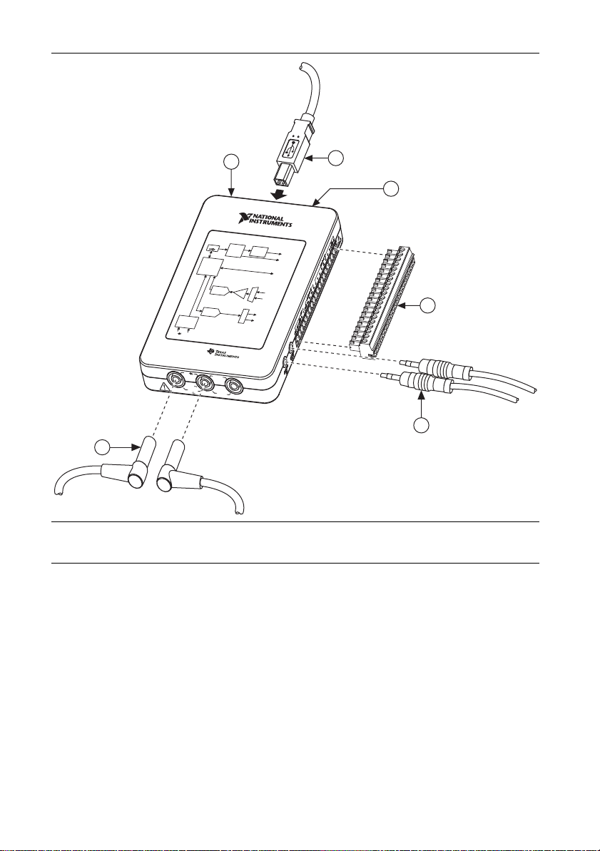
Setting up Your NI myDAQ Device.................................................................................7
Connecting Signals ...........................................................................................................9
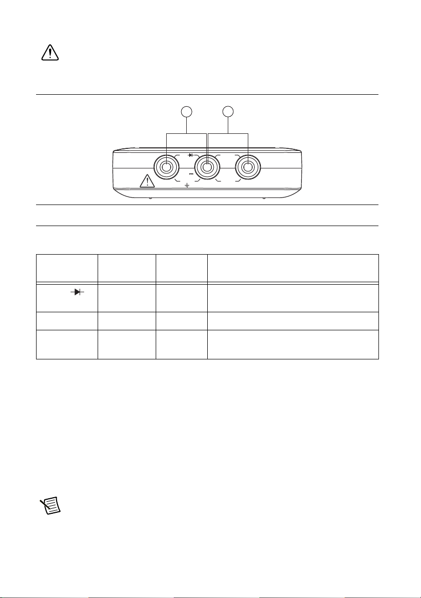
Connecting Analog Input Signals ..................................................................................... 10
NI myDAQ DMM Fuse Replacement .............................................................................. 13
Digital I/O (DIO) and Counters/Timers.................................................................................... 15
Using NI myDAQ with NI ELVISmx Software Instruments................................................... 16
NI ELVISmx Instrument Launcher ..................................................................................17
Digital Multimeter (DMM)............................................................................................... 18
Oscilloscope (Scope) ........................................................................................................ 19
Function Generator (FGEN) .............................................................................................20
Bode Analyzer .................................................................................................................. 21
Dynamic Signal Analyzer (DSA) ..................................................................................... 22
Arbitrary Waveform Generator (ARB)............................................................................. 23
Digital Reader ................................................................................................................... 24
Digital Writer.................................................................................................................... 25
Example: Measuring a Signal Using the NI ELVISmx Oscilloscope
with NI myDAQ ............................................................................................................ 26
Using NI myDAQ with LabVIEW ...........................................................................................27
NI ELVISmx Express VIs in LabVIEW...........................................................................27
Example: Measuring Signals Using the NI ELVISmx Oscilloscope Express VI
with NI myDAQ ............................................................................................................ 28
Using NI-DAQmx with NI myDAQ ................................................................................30
Example: Measuring Audio Pass-Through in LabVIEW with NI myDAQ .....................30
Texas Instruments Components in NI myDAQ........................................................................34
Resource Conflicts ....................................................................................................................35
Additional Resources ................................................................................................................ 37
Related Documentation..................................................................................................... 37
Other Resources ................................................................................................................ 38
Common Terms and Acronyms........................................................................................ 38
Warranty ...........................................................................................................................39
Worldwide Support and Services .....................................................................................39
Safety Information
Caution Do not operate the hardware in a manner not specified in this document
and in the user documentation. Misuse of the hardware can result in a hazard. You
can compromise the safety protection if the hardware is damaged in any way. If the
hardware is damaged, return it to National Instruments for repair.
Clean the hardware with a soft, nonmetallic brush. Make sure that the hardware is completely
dry and free from contaminants before returning it to service.

NI myDAQ User Guide |© National Instruments |3
Electromagnetic Compatibility Guidelines
Cautions To ensure the specified EMC performance:
•The USB cable must be less than 2.0 m (6.6 ft) in length.
•The length of any wire or cable connected to the 20-pin screw terminal
connector must be no longer than 0.3 m (1 ft).
•The length of any wire or cable connected to the Audio or DMM ports must be
no longer than 3 m (10 ft).
This product was tested and complies with the regulatory requirements and limits for
electromagnetic compatibility (EMC) as stated in the product specifications. These requirements
and limits are designed to provide reasonable protection against harmful interference when the
product is operated in its intended operational electromagnetic environment.
This product is intended for use in residential, commercial, and industrial locations. There is no
guarantee that harmful interference will not occur in a particular installation or when the product
is connected to a test object. To minimize the potential for the product to cause interference to
radio and television reception or to experience unacceptable performance degradation, install
and use this product in strict accordance with the instructions in the product documentation.
Furthermore, any changes or modifications to the product not expressly approved by National
Instruments could void your authority to operate it under your local regulatory rules.
NI myDAQ Hardware Overview
NI myDAQ provides analog input (AI), analog output (AO), digital input and output (DIO),
audio, power supplies, and digital multimeter (DMM) functions in a compact USB device.
Tip The Common Terms and Acronyms section has a list of acronyms and terms
that you will see in this manual, and in many engineering and measurement
documents and websites.
Integrated circuits supplied by Texas Instruments form the power and analog I/O subsystems of
NI myDAQ. Figure 2 depicts the arrangement and function of the NI myDAQ subsystems. Refer
to Table 5 for more information on all of the Texas Instruments components used in NI myDAQ.

4|ni.com |NI myDAQ User Guide
Figure 2. NI myDAQ Hardware Block Diagram
Analog Input (AI)
There are two analog input channels on NI myDAQ. These channels can be configured either as
general-purpose high-impedance differential voltage input or audio input. The analog inputs are
multiplexed, meaning a single analog-to-digital converter (ADC) is used to sample both
channels. In general-purpose mode, you can measure up to ±10 V signals. In audio mode, the
two channels represent left and right stereo line level inputs. Analog inputs can be measured at
up to 200 kS/s per channel, so they are useful for waveform acquisition. Analog inputs are used
in the NI ELVISmx Oscilloscope, Dynamic Signal Analyzer, and Bode Analyzer instruments.
Analog Output (AO)
There are two analog output channels on NI myDAQ. These channels can be configured as either
general-purpose voltage output or audio output. Both channels have a dedicated
digital-to-analog converter (DAC), so they can update simultaneously. In general-purpose
mode, you can generate up to ±10 V signals. In audio mode, the two channels represent left and
right stereo outputs.
Caution f using earphones to listen to the audio output of the NI myDAQ, ensure
that the volume is set to a safe level. Listening to audio signals at a high volume may
result in permanent hearing loss.
Note: NI myDAQ components may be changed or substituted without notice.
Protection
Circuit
(CSD25302Q2)
DC/DC
Isolation
Transformer
LDO
Regulator
(TPS76433)
LDO
Regulator
(TPS76433)
VBUS
Isolated +3.3V
+15 V
+3.3V
+1.2 V
+5 V
–15 V
USB-STC3
Digital
Isolator
(ISO7241)
DMM
Shift
Register
(SN74AHC595)
Switch
(TS5A3159)
Regulator
(TPS61170)
Isolation
Barrier
HI HI
COM
DAC
(DAC8551)
Switch
(TS12A44514)
Gain
(TLE2082)
OP AMP
(OPA1642)
Audio AMP
(TPA6110A2)
AO 0
AO 1
Line Out R
Line Out L
Instrumentation
Amplifier
(OPA1642) Channel
Multiplexer
AI 0–
AI 0+
AI 1–
AI 1+
Line In L
Line In R
8DIO x
USB Connector
Regulator
(TPS62007)
Regulator
(TPS62003)
ADC
(ADS8319)
OP AMP
(OPA1642)
Current
Limiter
(TPS2553)
(V Ω) (A)
+3.3V
LDO
Regulator
(TPS71501)
Isolated +5 V

NI myDAQ User Guide |© National Instruments |5
Analog outputs can be updated at up to 200 kS/s per channel, making them useful for waveform
generation. Analog outputs are used in the NI ELVISmx Function Generator, Arbitrary
Waveform Generator, and Bode Analyzer instruments.
Digital Input/Output (DIO)
There are eight DIO lines on NI myDAQ. Each line is a Programmable Function Interface (PFI),
meaning that it can be configured as a general-purpose software-timed digital input or output, or
it can act as a special function input or output for a digital counter. Refer to Digital I/O (DIO)
and Counters/Timers section for more information about the counter on NI myDAQ.
Note The digital I/O lines are 3.3 V LVTTL and are tolerant to 5 V inputs. The
digital output is not compatible with 5 V CMOS logic levels.
Power Supplies
There are three power supplies available for use on NI myDAQ. +15 V and -15 V can be used
to power analog components such as operational amplifiers and linear regulators. +5 V can be
used to power digital components such as logic devices.
The total power available for the power supplies, analog outputs, and digital outputs is limited
to 500 mW (typical)/100 mW (minimum). To calculate the total power consumption of the
power supplies, multiply the output voltage by the load current for each voltage rail and sum
them together. For digital output power consumption, multiply 3.3 V by the load current. For
analog output power consumption, multiply 15 V by the load current. Using audio output
subtracts 100 mW from the total power budget.
For example, if you use 50 mA on +5 V, 2 mA on +15 V, 1 mA on -15 V, use four DIO lines to
drive LEDs at 3 mA each, and have a 1 mA load on each AO channel, the total output power
consumption is:
5 V × 50 mA = 250 mW
|+15 V| × 2 mA = 30 mW
|-15 V| × 1 mA = 15 mW
3.3 V × 3 mA × 4 = 39.6 mW
15 V × 1 mA × 2 = 30 mW
Total output power consumption = 250 mW + 30 mW + 15 mW + 39.6 mW +
30 mW = 364.6 mW
Digital Multimeter (DMM)
The NI myDAQ DMM provides the functions for measuring voltage (DC and AC), current (DC
and AC), resistance, and diode voltage drop.
DMM measurements are software-timed, so update rates are affected by the load on the
computer and USB activity.

6|ni.com |NI myDAQ User Guide
NI myDAQ Software Overview
NI ELVISmx Driver Software
NI ELVISmx is the driver software that supports NI myDAQ. NI ELVISmx uses
LabVIEW-based software instruments to control the NI myDAQ device, providing the
functionality of a suite of common laboratory instruments. Refer to the Using NI myDAQ with
NI ELVISmx Software Instruments section for information on the NI ELVISmx suite of
measurement instruments.
NI ELVISmx is located on your driver software installation media included in the NI myDAQ
kit, or can be found by searching for ELVISmx on the Drivers and Updates page at ni.com/
drivers. To determine the version of NI ELVISmx software support required for your version
of LabVIEW, go to ni.com/info and enter the Info Code exsbw6.
NI LabVIEW and NI ELVISmx Express VIs
Also installed with NI ELVISmx are the LabVIEW Express VIs, which use NI ELVISmx
software instruments to program NI myDAQ with more enhanced functionality. For more
information on the NI ELVISmx Express VIs, refer to the Using NI myDAQ with LabVIEW
section.
Note NI ELVISmx supports LabVIEW (32 bit). To use NI ELVISmx with
LabVIEW on a 64-bit operating system, you must have LabVIEW (32 bit) installed.
NI myDAQ and NI Multisim
You can use NI ELVISmx instruments in NI Multisim to simulate a circuit, measure the real
signals with NI myDAQ, and compare simulated and acquired data. To see step-by-step
instructions for using NI ELVISmx instruments in NI Multisim, refer to Using NI ELVISmx in
NI Multisim help file, installed with NI ELVISmx. To access this help file, go to Start»
All Programs»National Instruments»NI ELVISmx for NI ELVIS & NI myDAQ»Using
NI ELVISmx in NI Multisim.
Getting Started
Getting started with NI myDAQ is a simple process, but it is important to ensure that you install
the right components in the correct order. To get started with your NI myDAQ, complete the
following steps:
1. Install the NI myDAQ Software Suite from the DVD shipped with your device.
The NI myDAQ Software Suite installs application software (NI LabVIEW, NI Multisim)
first, and then installs the NI ELVISmx driver software.
Note If you are not installing software from the NI myDAQ Software Suite media,
make sure to install all application software before installing the driver software.

NI myDAQ User Guide |© National Instruments |7
2. Connect the cable from the computer Hi-Speed USB port to the USB port on the device.
The computer will recognize the NI myDAQ and the NI ELVISmx Instrument Launcher
appears. You can also manually open NI ELVISmx Instrument Launcher by selecting
Start»All Programs»National Instruments»NI ELVISmx for NI ELVIS &
NI myDAQ»NI ELVISmx Instrument Launcher.
Caution To ensure the specified EMC performance, the USB cable must be less
than 2.0 m (6.6 ft) in length.
Making Signal Connections with NI myDAQ
Setting up Your NI myDAQ Device
Caution Insert and remove the 20-position screw terminal connector aligned
evenly to the NI myDAQ. Inserting the screw terminal connector at an angle to the
NI myDAQ may cause damage to the connector.
The screw terminal connector must snap securely into place to ensure proper signal
connection.

8|ni.com |NI myDAQ User Guide
Figure 3. NI myDAQ Connection Diagram
1NImyDAQ
2USBCable
3LED
4 20-Position Screw Terminal Connector
5 Audio Cable
6 DMM Banana Cable
NI myDAQ
AUDIO IN
Analog Input
USB
Power Supply
Gain
Analog Output
Digital Input/Output
AUDIO OUT
NI myDAQ SystemDiagram
AI
DIO
5V
±15 V
DC-toDC
Converter
Analog-
to-Digital
Converter
Digital-
to-Analog
Converter
Digital
Multimeter
Analog ICs
supplied by
HIHI
1A
1 A
MAX
MAX
60V
20Vrms
20Vrms
MAX
MAX
VΩ
VΩ
A
COM
VΩ A
SystemTiming
Controller
Current
Limiter
AO
Switch
Multiplexer
12
3
4
5
6

NI myDAQ User Guide |© National Instruments |9
Connecting Signals
Figure 4 shows the available audio, AI, AO, DIO, GND, and power signals accessed through the
3.5 mm audio jacks and screw terminal connections. Refer to Table 1 for descriptions of these
signals.
Cautions Signal wires must be securely affixed and screwed down in the screw
terminal connector to ensure proper connection.
To ensure the specified EMC performance:
•The length of any wire or cable connected to the 20-pin screw terminal
connector must be no longer than 0.3 m (1 ft).
•The length of any wire or cable connected to the Audio or DMM ports must be
no longer than 3 m (10 ft).
Figure 4. NI myDAQ 20-Position Screw Terminal I/O Connector
Table 1. Screw Terminal Signal Descriptions
Signal
Name Reference Direction Description
AUDIO IN —Input Audio Input—Left and right audio inputs
on a stereo connector
AUDIO OUT —Output Audio Output—Left and right audio
outputs on a stereo connector
+15V/-15V AGND Output +15 V/-15 V power supplies
AGND — — Analog Ground—Reference terminal for
AI, AO, +15 V, and -15 V
AO 0/AO 1 AGND Output Analog Output Channels 0 and 1
AI 0+/AI 0-;
AI 1+/AI 1-
AGND Input Analog Input Channels 0 and 1
DIO <0..7> DGND Input or
Output
Digital I/O Signals—General-purpose
digital lines or counter signals
DGND — — Digital Ground—Reference for the DIO
lines and the +5 V supply
5V DGND Output 5 V power supply
AUDIO
IN
AUDIO
OUT

10 |ni.com |NI myDAQ User Guide
Figure 5 shows the DMM connections on the NI myDAQ. Table 2 describes these signals.
Caution 60 VDC/20 Vrms maximum. Do not plug digital multimeter probes into
circuits with Hazardous Voltages, such as wall outlets.
Figure 5. Connections for DMM Measurements
Connecting Analog Input Signals
When configuring the input channels and making signal connections, you must first determine
whether the signal sources are floating or ground referenced. The following sections describe
these two signal types.
Ground-Referenced Signal Sources
A ground-referenced signal source is connected to the building system ground, so it is already
connected to a common ground point with respect to the NI myDAQ device, assuming that the
computer is plugged into the same power system. Instruments or devices with nonisolated
outputs that plug into the building power system are ground-referenced signal sources.
Note Most laptop computers have isolated power supplies, and are consequently
not connected to the building ground system. In these cases, treat the analog input
signal as floating with respect to NI myDAQ.
1 Connectors for Voltage/Resistance/Diode/Continuity
2 Connectors for Current
Table 2. DMM Signal Descriptions
Signal
Name Reference Direction Description
HI (VΩ)COM Input Positive terminal for voltage, resistance,
and diode measurements
COM — — Reference for all DMM measurements
HI (A) COM Input Positive terminal for current measurements
(Fused: F 1.25 A 250 V Fast-Acting)
12
HIHI COM
1
A
A
MAX
MAX
6
0 V
0 V
20 Vrms
20 Vrms
MAX
MAX
A
V
Ω

NI myDAQ User Guide |© National Instruments |11
The difference in ground potential between two instruments connected to the same building power
system is typically between 1 and 100 mV. This difference can be much higher if power
distribution circuits are improperly connected. If a grounded signal source is improperly measured,
this difference might appear as a measurement error. Connect the differential analog inputs across
the signal source and do not connect the NI myDAQ AGND pin to the grounded source.
Figure 6. Ground-Referenced Differential Connection
Floating Signal Sources
A floating signal source is not connected to the same ground reference as NI myDAQ, but
instead has an isolated reference point. Some examples of floating signal sources are
battery-powered devices, outputs of transformers, thermocouples, optical isolator outputs, and
isolation amplifiers. An instrument or device that has an isolated output is a floating signal
source. You must connect the ground reference of a floating signal to an NI myDAQ AGND pin
through a bias resistor or jumper wire to establish a local or onboard reference for the signal.
Otherwise, the measured input signal varies as the source floats out of the common-mode input
range.
The easiest way to reference the source to AGND is to connect the positive side of the signal to
AI+ and connect the negative side of the signal to AGND as well as to AI- without using
resistors. This connection works well for DC-coupled sources with low source impedance (less
than 100 Ω).
Figure 7. Differential Connections for Floating Signal Sources without Resistors
For larger source impedances, however, this connection leaves the differential signal path
significantly off balance. Noise that couples electrostatically onto the positive line does not
couple onto the negative line because it is connected to ground. This noise appears as a
differential-mode signal instead of a common-mode signal, and thus appears in your data. In this
case, instead of directly connecting the negative line to AGND, connect the negative line to
AGND through a resistor that is about 100 times the equivalent source impedance. The resistor
puts the signal path nearly in balance, so that about the same amount of noise couples onto both
+
–
+
–
AI+
AGND
Signal Source
AI–
+
–
AI+
AGND
Signal Source
Rsource >100
Ω
AI–
+
–

12 |ni.com |NI myDAQ User Guide
connections, yielding better rejection of electrostatically coupled noise. This configuration does
not load down the source.
Figure 8. Differential Connections for Floating Signal Sources with a Single Resistor
You can fully balance the signal path by connecting another resistor of the same value between
the positive input and AGND, as shown in Figure 9. This fully balanced configuration offers
slightly better noise rejection, but has the disadvantage of loading the source down with the
series combination (sum) of the two resistors. If, for example, the source impedance is 2 kΩand
each of the two resistors is 100 kΩ, the resistors load down the source with 200 kΩand produce
a -1% gain error.
Figure 9. Differential Connections for Floating Signal Sources with Two Resistors
Both positive and negative analog input lines require a DC path to ground in order for the
instrumentation amplifier to work. If the source is AC coupled (capacitively coupled), a resistor
is needed between the positive input and AGND. If the source has low impedance, choose a
resistor that is large enough not to significantly load the source but small enough not to produce
significant input offset voltage as a result of input bias current (typically 100 kΩto 1 MΩ). In
this case, connect the negative input directly to AGND. If the source has high output impedance,
balance the signal path as previously described using the same value resistor on both the positive
and negative inputs.
+
–
+
–
AI+
AGND
Signal Source
Rsource >100
Ω
AI–
+
–
+
–
AI+
AGND
Signal Source
Rsource >100
Ω
AI–

NI myDAQ User Guide |© National Instruments |13
NI myDAQ DMM Fuse Replacement
NI myDAQ has a fuse to protect the device from overcurrent through HI (A) current
measurement input on the DMM. If the NI ELVISmx DMM software instrument always reads
0 A current, the cause may be a blown fuse.
Testing Your Fuse
To test for a blown fuse, complete the following steps.
1. Using a banana cable, connect the HI (V) and HI (A) DMM terminals.
2. Launch the NI ELVISmx Digital Multimeter (DMM) software instrument from the
NI ELVISmx Instrument Launcher, located at Start»All Programs»National
Instruments»NI ELVISmx for NI ELVIS & NI myDAQ»NI ELVISmx Instrument
Launcher.
3. Select the Resistance mode by clicking the Resistance button .
4. Click Run.
5. If the fuse is blown, the display will show +Over, indicating a disconnected circuit path.
Replace the fuse and complete the procedure again.
Replacing the Fuse
Replace broken fuses with a 1.25 A Fast-Acting sand-filled 5 × 20 mm fuse (Littelfuse part
number 02161.25 at www.littelfuse.com).
To replace a broken fuse, complete the following steps.
1. Power down the device by properly disconnecting it from the PC and removing the USB
cable.
2. Remove the screw terminal connector and all other signal cables from the device.
3. Loosen the four Phillips screws that attach the bottom of the enclosure to the device, and
remove the top lid of the enclosure.
Caution Do not remove the board from the bottom half of the NI myDAQ
enclosure.

14 |ni.com |NI myDAQ User Guide
4. Replace the broken fuse while referring to Figure 10 for the fuse location, taking care to not
damage any components on the board.
Figure 10. NI myDAQ Fuse Location
5. Replace the lid and screws.
1 Enclosure Screws
2 Internal Fuse—1.25 A Fast-Acting (Littelfuse Part Number 02161.25)
1
2
1
NI myDAQ
NI myDAQ
AUDIO IN
Analog Input
USB
Power Supply
Gain
Analog Output
Digital Input/Output
AUDIO OUT
NI myDAQ System Diagram
AI
DIO
5 V
±15 V
DC-toDC
Converter
Analog-
to-Digital
Converter
Digital-
to-Analog
Converter
Digital
Multimeter
Analog ICs
supplied by
VΩ A
System Timing
Controller
Current
Limiter
AO
Switch
Multiplexer
HI HI
1A
1A
MAXMAX
60
V
20 Vrms
20 Vrms
MAX
MAX
COM
VΩVΩ
A

NI myDAQ User Guide |© National Instruments |15
Digital I/O (DIO) and Counters/Timers
There are eight, software-timed DIO lines on the NI myDAQ that can be individually configured
for input or output. Additionally, lines DIO <0..4> can be configured for counter/timer
functionality. The input—accessed through DIO 0, DIO 1, and DIO 2 signals configured as a
counter—is used for counter, timer, pulse width measuring, and quadrature encoding
applications.
When using the counter/timer, the Source is accessed through DIO 0, the Gate through DIO 1,
the Auxiliary Input through DIO 2, the Output through DIO 3, and the Frequency Output
through DIO 4. When using the counter/timer as a quadrature encoder, A, Z, and B correspond
to DIO 0, DIO 1, and DIO 2, respectively. In some instances, the software may refer to the
output lines as PFI as opposed to DIO. Refer to Table 3 for a list of the corresponding
counter/timer signals assignments through the DIO terminals.
For more information about event timing requirements, refer to the NI myDAQ Specifications
document. For more detailed information on using counter/timers with NI myDAQ, refer to the
KnowledgeBase document How Do I Use the NI myDAQ Counter?. To access this document,
go to ni.com/info and enter the Info Code mydaqcounter.
Table 3. NI myDAQ Counter/Timer Signal Assignments
NI myDAQ
Signal
Programmable
Function Interface
(PFI)
Counter/Timer
Signal
Quadrature Encoder
Signal
DIO 0 PFI 0 CTR 0 SOURCE A
DIO 1 PFI 1 CTR 0 GATE Z
DIO 2 PFI 2 CTR 0 AUX B
DIO 3*PFI 3 CTR 0 OUT —
DIO 4 PFI 4 FREQ OUT —
*Pulse-width modulation (PWM) pulse train measurements are generated through DIO 3

16 |ni.com |NI myDAQ User Guide
Using NI myDAQ with NI ELVISmx Software
Instruments
Note Before opening an NI ELVISmx software instrument, make sure that the
myDAQ device is connected to the system and is ready to use. After the myDAQ is
connected to the system, the blue LED by the connector lights, indicating the device
is ready for use. The NI ELVISmx Instrument Launcher then launches automatically.
NI ELVISmx provides a collection of software instruments, created in LabVIEW, and the source
code for the instruments. You cannot directly modify the executable files, but you can modify or
enhance the functionality of these instruments by modifying the LabVIEW code, which installs
in the following location:
• Windows XP/2000:
C:\Documentsand Settings\All Users\Shared Documents\National
Instruments\NI ELVISmx Source Code
• Windows 7/Vista:
C:\Users\Public\Public Documents\National Instruments\NI ELVISmx
Source Code
Note For a detailed explanation of the NI ELVISmx software instruments,
instructions for taking a measurement with each instrument, and information on the
other NI ELVISmx Instrument Launcher features, refer to the NI ELVISmx Help. To
access this help file, click the NI ELVISmx Help icon on the Resources tab of the
NI ELVISmx Instrument Launcher.

NI myDAQ User Guide |© National Instruments |17
NI ELVISmx Instrument Launcher
The NI ELVISmx Instrument Launcher provides access to the NI ELVISmx software
instruments, additional featured instruments, lab exercises, documentation and online resource
links, and functionality to add data and reference files. To open the Instrument Launcher,
navigate to Start»All Programs»National Instruments»NI ELVISmx for NI ELVIS &
NI myDAQ»NI ELVISmx Instrument Launcher. This opens the suite of NI ELVISmx
software instruments.
Figure 11. NI ELVISmx Instrument Launcher
To launch an instrument, click the button corresponding to the desired instrument. Select the
NI myDAQ device from the Device control pull-down dialog.
Some instruments perform similar operations using the same resources of the NI myDAQ
hardware and therefore cannot run at the same time. If you launch two instruments with
overlapping functionality that cannot run at the same time, the NI ELVISmx software generates
an error dialog describing the conflict. The instrument with the error is disabled and will not
function until the conflict is resolved. For information about possible resource conflicts, refer to
the Resource Conflicts section.

18|ni.com |NI myDAQ User Guide
Digital Multimeter (DMM)
The NI ELVISmx Digital Multimeter (DMM) is a stand-alone instrument that controls the basic
DMM capabilities of NI myDAQ. This commonly used instrument can perform the following
types of functions:
• Voltage measurement (DC and AC)
• Current measurement (DC and AC)
• Resistance measurement
• Diode test
• Audible continuity test
Make connections for measurements to the DMM banana jacks on the device. This instrument
has the following measurement parameters:
• DC voltage: 60 V, 20 V, 2 V, and 200 mV ranges
• AC voltage: 20 V, 2 V, and 200 mV ranges
• DC current: 1 A, 200 mA, and 20 mA ranges
• AC current: 1 A, 200 mA, and 20 mA ranges
• Resistance: 20 MΩ, 2 MΩ, 200 kΩ, 20 kΩ, 2 kΩ, and 200 Ωranges
• Diode: 2 V range
• Resolution (number of significant digits for display): 3.5
Figure 12. NI ELVISmx Digital Multimeter

NI myDAQ User Guide |© National Instruments |19
Oscilloscope (Scope)
The NI ELVISmx Oscilloscope (Scope) displays voltage data for analysis. This instrument
provides the functionality of the standard desktop oscilloscope found in typical undergraduate
laboratories. The NI ELVISmx Oscilloscope has two channels and provides scaling and position
adjustment knobs along with a modifiable timebase. The autoscale feature allows you to adjust
the voltage display scale based on the peak-to-peak voltage of the AC signal for the best display
of the signal.
The computer-based scope display has the ability to use cursors for accurate screen
measurements. This instrument has the following measurement parameters:
• Channel Source: Channels AI 0 and AI 1; AudioInput Left, and AudioInput Right. You can
use AI channels or AudioInput channels, but not a combination of both.
• Coupling: AI Channels support DC Coupling only. AudioInput Channels support
AC Coupling only.
• Scale Volts/Div: AI channels—5 V, 2 V, 1 V, 500 mV, 200 mV, 100 mV, 50 mV, 20 mV,
10 mV and for AudioInput Channels—1 V, 500 mV, 200 mV, 100 mV, 50 mV, 20 mV,
10 mV.
• Sample Rate: The Max Sample Rate available for AI and AudioInput Channels: 200 kS/s
when either one or both channels are configured.
• Timebase Time/Div: The available values for both AI and AudioInput channels: 200 ms to
5µs.
• Trigger settings: Immediate and Edge Trigger Types are supported. When using Edge
Trigger Type, you can specify a Horizontal Position of 0% to 100%.
Figure 13. NI ELVISmx Oscilloscope

20 |ni.com |NI myDAQ User Guide
Function Generator (FGEN)
The NI ELVISmx Function Generator (FGEN) generates standard waveforms with options for
the type of output waveform (sine, square, or triangle), amplitude selection, and frequency
settings. In addition, the instrument offers DC offset setting, frequency sweep capabilities, and
amplitude and frequency modulation. The FGEN uses AO 0 or AO 1 on the screw terminal
connector.
This instrument has the following measurement parameters:
• Output channel: AO 0 or AO 1
• Frequency range: 0.2 Hz to 20 kHz
Figure 14. NI ELVISmx Function Generator
Table of contents
Other National Instruments Industrial Equipment manuals

National Instruments
National Instruments NI 9476 User manual

National Instruments
National Instruments NI 9475 User manual

National Instruments
National Instruments NI 9220 User manual

National Instruments
National Instruments NI 9209 User manual

National Instruments
National Instruments NI SMD-7620 User manual

National Instruments
National Instruments NI 9264 User manual

National Instruments
National Instruments NI-9230 User manual

National Instruments
National Instruments VXIpc 770 Series User manual

National Instruments
National Instruments NI 5751 User manual

National Instruments
National Instruments NI 9421 User manual