Dell S2721DGFA User manual

Product Announcement:
This product is certificated to meet RoHS
Directive and Lead-Free produced definition.
Using approved critical components only is
recommended when the situation to replace
defective parts. Vender assumes no liability
express or implied, arising out of any unauthorized
modification of design or replacing non-RoHS
parts. Service providers assume all liability.
Qualified Repairability:
Proper service and repair is important to the safe,
reliable operation of all series products. The
service providers recommended by vender should
be aware of notices listed in this service manual in
order to minimize the risk of personal injury when
perform service procedures. Furthermore, the
possible existed improper repairing method may
damage equipment or products. It is recommended
that service engineers should have repairing
knowledge, experience, as well as appropriate
product training per new model before performing
the service procedures.
NOTICE:
! To avoid electrical shocks, the products should be
connected to an authorized power cord, and turn
off the master power switch each time before
removing the AC power cord.
! To prevent the product away from water or
expose in extremely high humility environment.
! To ensure the continued reliability of this
product, use only original manufacturer’s
specified parts.
! To ensure following safety repairing behavior, put
the replaced part on the components side of
PWBA, not solder side.
! To ensure using a proper screwdriver, follow the
torque and force listed in assembly and
disassembly procedures to unscrew screws.
! Using Lead-Free solder to well mounted the
parts.
! The fusion point of Lead-Free solder requested in
the degree of 220°C.
1. Important Safety Notice

2. Exploded view diagram with list of items
Front
trim
Panel
Mid
Frame
IF and
Power
BD
Main
bracket
Joystick
BD
Joystick
Key
OSD key
Stand and
Base

3. Wiring Connectivity Diagram
2nwoD0.3BSU1nwoD0.3BSU
AC In
Power Board
Panel
Function Key Board
USB3.0
Down4
USB3.0
Down3
USB Board
Interface Board
Audio Line Out
HDMI 2.0DP 1.4
USB Up-Stream
HDMI 2.0
USB Down-Stream USB Down-Stream
Power Key Board
LED Light Bar

4. Disassembly and Assembly Procedures
S2
4.1 Disassembly Procedures:
S1
S3
Remove the monitor stand base:
1. Place the monitor on a soft cloth or cushion.
2. Press and hold the stand-release button.
3. Lift the stand up and away from the monitor.
Wedge your fingers between the rear cover and the
middle bezel on the corners of the top side of the
monitor to release the rear cover, then use one hand
to press the middle bezel, the other hand to pull up
carefully the rear cover in order of arrow preference
for unlocking mechanisms of rear cover.
Use a Philips-head screwdriver to remove four
screws for unlocking mechanisms.
(No.1~4 screw size=M4x8; Torque=10~11kgfxcm)
4
3
2
3
1
23
41
Lift the rear cover up carefully. Disconnect the USB
FFC cable, joystick key cable and power key cable
from the connectors of the interface board, and then
disconnect the back LED light bar cable from the
connector of the power board, and then remove the
rear cover.
S4
Use a Philips-head screwdriver to remove one screw
for unlocking the USB board unit, then release the
USB board unit and put it aside.
(No.1 screw size=M3x6, Torque=4±0.5kgfxcm)
S5
Use a Philips-head screwdriver to remove 4pcs
screws for unlocking the joystick key board with the
rear cover. Tear off the joystick key tapes and release
the joystick key board from the hook of the rear cover.
(No.1~4 screw size=M2x0.2, Torque=0.8±0.2kgfxcm)
1
1
2
4
3
S6
Necessary repair and test equipment:
1. Philips-head screwdriver

4. Disassembly and Assembly Procedures
Tear off all the mylar and tapes, then use a Philips-
head screwdriver to remove 7pcs screws for
releasing the diffuser, reflector and LGP.
Remove the middle bezel and put it into a fixture jip,
then use a Philips-head screwdriver to remove 1pcs
screw for unlocking the power key board with the
front bezel.
(No.1 Screw size= M2x2.4, Torque=0.8±0.2kgfxcm)
S10
1
6
5
42
3
7
Tear off the mylar tape on the position as the picture
below shown. Use a Philips-head screwdriver to
remove 13pcs screws for unlocking the middle bezel
with the panel module. Use a Philips-head
screwdriver to remove 2pcs screws for unlocking the
middle bezel with the front bezel.
(No.1~13 Screw size= M3x5, Torque=3~4kgfxcm;
No.14~15 Screw size= M2x2.7,Torque=1~2kgfxcm)
Tear off all the adhesive tapes for releasing the panel
lamp cable, then disconnect the cable away from the
connectors of the power board and panel.
1
Lift up the panel module and pull out the front bezel
for releasing the front bezel.
U
.
se a Philips-head screwdriver to remove 4pcs
screws for locking the bracket chassis module with
the panel
(No.1~4 Screw size= M3x0.5x2.8, Torque=5~6kgfxcm)
S11
S12
23
4
1
S7
S8
S9

4. Disassembly and Assembly Procedures
Remove the circuit boards from the
disconnect all
of the cables.
bracket
chassis module carefully, and then
S15
Turn over the bracket chassis module. Use a Philips-
head screwdriver to remove screws for
unlocking power board and interface board, and
then release the EDP cable from the hook of the
bracket.
6pcs
(No.1 screw size=M4x8, Torque=6±0.5kgfxcm;
No.2~7 screw size=M3x7.5, Torque=6±0.5kgfxcm)
S14
Tear off the adhesive tape, and then disconnect the
EDP cable from the connector of the panel module,
then put the bracket chassis on a protective cushion.
S13
3
4
2
1
56

4. Disassembly and Assembly Procedures
Turn over a power board and put the power board
into the bracket chassis, settle the panel power
cable to the correct position.
Place a bracket chassis base on a protective
cushion, then stick 1pcs Silicon sheet on the position
as the picture below shown.
4.2 Assembly Procedures:
S2
S1
S3
S5
Take 1pcs interface board, connect 1pcs EDP cable
to the interface board, then connect the cable of the
power board to the interface board. Turn over the
interface board and locate it into the bracket. Use a
Philips-head screwdriver to tighten 6pcs screws for
locking the circuit board, then locate the EDP cable
into the hook of the bracket.
(No.1 screw size=M4x8, Torque=6±0.5kgfxcm;
No.2~6 screw size=M3x7.5, Torque=6±0.5kgfxcm)
3
4
2
1
56
S4
Panel preparation: Take out 1pcs panel module from
the carton, remove the protective film by tearing off
the tapes, then Examine the panel surface
according to inspection criteria. Turn over the panel
to place screen faced down for later assembling.
Move the bracket chassis module close to the panel
module, and then put the bracket on the back of the
panel module. Connect the EDP cable to the
connector of the panel module, then fix the EDP
cable with tape on the back of cable as the picture
below shown.
23
4
1
Adjust the bracket chassis module, and then u
.
se a
Philips-head screwdriver to tighten 4pcs screws for
locking the bracket chassis module with the panel
module
(No.1~4 Screw size= M3x0.5x2.8, Torque=5~6kgfxcm)
S6

4. Disassembly and Assembly Procedures
Fix the power key cable by tear off 2pcs tape papers
on the back of the cable. Paste 1pcs mylar tape on
the specific position of the panel as the picture below
shown. Use a Philips-head screwdriver to tighten
13pcs screws for locking the middle bezel with the
panel module.
(No.1~13 Screw size= M3x5, Torque=3~4kgfxcm)
S10
Take 1pcs front bezel, lift up the panel module and
then assemble the front bezel with the panel module
unit.
S7
Take 1pcs power key board, 1pcs key cable and
1pcs middle bezel, connect the key cable to the
connector of the power key board, and then locate
the power key board to the specific position of the
middle bezel. Put the unit into a fixture, use a Philips-
head screwdriver to tighten 1pcs screw for locking
the power key board with the middle bezel.
(No.1 Screw size= M2x2.4, Torque=0.8±0.2kgfxcm)
S8
1
Assemble the middle bezel unit with the front bezel
and panel module. Use a Philips-head screwdriver to
tighten 2pcs screws for locking the middle bezel with
front bezel.
(No.1~2 Screw size= M2x2.7,Torque=1~2kgfxcm)
S9
12
Take 1pcs panel lamp cable to connect the power
board and panel module, then locate the lamp cable
into the hooks of the middle bezel, then fix the lamp
cable with 3pcs adhesive tapes as the following
picture shown.
S11
Take 1pcs LGP, 1pcs reflector and 1pcs rear cover,
put the rear cover on a cushion foam, assemble the
LGP with the rear cover first, then assemble the
reflector with the LGP as the picture below shown.
S12
LGP

4. Disassembly and Assembly Procedures
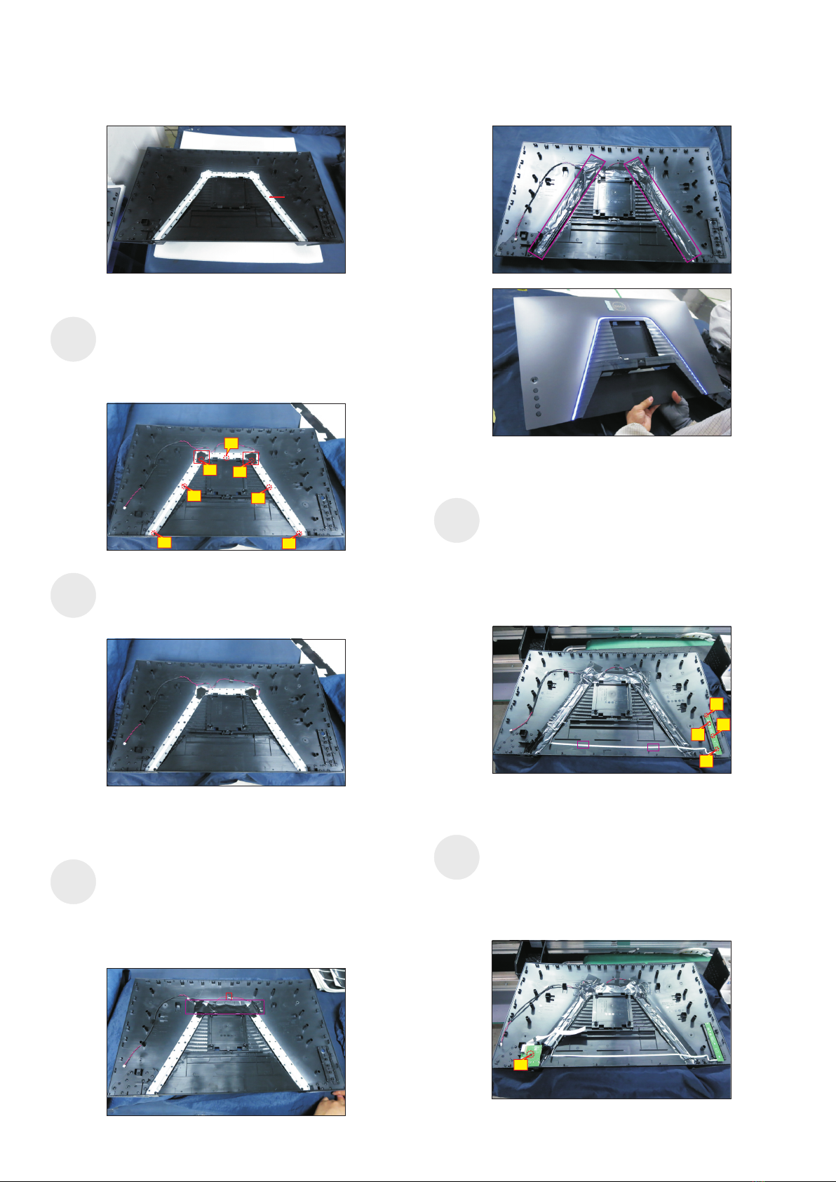
Paste 1pcs mylar tape to cover the light unit, then fix
the light cable with 1pcs acetate tape as the picture
below shown. Paste 2pcs mylar tape to cover the
light bar unit as the picture below shown. Make sure
not light-leaking between the mylar tapes,
then
connect the light cable to the circuit board, and
provide power supply to the light bar to check if light
bar work normally.
Assemble 1pcs left diffuser mylar and 1pcs right
diffuser mylar with the left and right corners as the
following picture. Use a Philips-head screwdriver to
tighten 7pcs screws for locking the diffuser, reflector
and LGP with the rear cover.
(No.1~7 screw size=M3x3.5x7, Torque=2~3kgfxcm)
Take 1pcs joystick key board, plug key cable to the
joystick key board, then locate the joystick key board
to the specific position of the rear cover, then use a
Philips-head screwdriver to tighten 4pcs screws for
locking the joystick key board with the rear cover.
Tear off the tape papers on the back of the key cable,
and then fix the key cable with tapes of the cable.
(No.1~4 screw size=M2x0.2, Torque=0.8±0.2kgfxcm)
S16
S15
reflector
S13
1
6
5
42
3
7
Take 1pcs LED lamp cable and 1pcs LED light board,
connect the cable to the LED light board, then locate
the light cable into the hooks of the rear cover, then
past 1pcs acetate tape to cover the light unit.
S14
Take 1pcs USB board and 1pcs connective cable.
Connect the cable to the USB board, paste 1pcs
conductive foam on the USB board, then locate
the USB unit into the hooks of a rear cover. Use a
Philips-head screwdriver to tighten 1pcs screw for
locking the USB unit with the rear cover.
(No.1 screw size=M3x6, Torque=4±0.5kgfxcm)
S17
1
1
2
4
3

Take a stand base close to the monitor. Fit the two
tabs on the upper part of the stand into the grooves on
the back of the monitor, and then lower the stand so
that the monitor mounting area snaps onto the stand.
Lift up the monitor to checking the gap between the
front bezel with panel module , then provide power
supply and a video signal to the monitor
, then turn on
the monitor for functionality check. Stick an energy
label on top left bezel of the monitor for European
region; Stick an energy label on top right bezel of the
monitor for Australia and New Zealand.
S20
S21
Use a Philips-head screwdriver to tighten 4pcs
screws for locking the rear cover with the assembled
unit. Paste 2pcs labels on the specific positions.
(No.1~4 screw size=M4x10; Torque=9±0.5kgfxcm)
S19
Move the assembled rear cover close to the
panel unit, then connect light bar cable to the
connector of the power board, then connect the
power key cable, joystick key cable and USB FFC
cable to the connectors of interface board. Put
down the rear cover and push the rear cover for
mechanisms engagement.
S18
23
41
4. Disassembly and Assembly Procedures

5. Trouble Shooting Instructions
Self-test
Yourmonitorprovidesaself-testfeaturethatallowsyoutocheckwhetheryour
monitorisfunctioningproperly.Ifyourmonitorandcomputerareproperlyconnected
butthemonitorscreenremainsdark,runthemonitorself-testbyperformingthe
followingsteps:
1. Turnobothyourcomputerandthemonitor.
2. Unplugthevideocablefromthebackofthecomputer.ToensureproperSelf-Test
operation,removealldigitalandtheanalogcablesfromthebackofcomputer.
3. Turnonthemonitor.
Thefloatingdialogboxshouldappearon-screen(againstablackbackground),ifthe
monitorcannotsenseavideosignalandisworkingcorrectly.Whileinself-testmode,
thepowerLEDremainswhite.Also,dependingupontheselectedinput,oneofthe
dialogsshownbelowwillcontinuouslyscrollthroughthescreen.
S2721DGF
The display will go into Power Save Mode in 4 minutes.
www.dell.com/support/S2721DGF
No DP Cable
Dell 27 Gaming Monitor
or
S2721DGF
The display will go into Power Save Mode in 4 minutes.
www.dell.com/support/S2721DGF
No HDMI 1 Cable
Dell 27 Gaming Monitor
1
or
S2721DGF
The display will go into Power Save Mode in 4 minutes.
www.dell.com/support/S2721DGF
No HDMI 2 Cable
Dell 27 Gaming Monitor
2
4. Thisboxalsoappearsduringnormalsystemoperationifthevideocable
becomesdisconnectedordamaged.
5. Turnoyourmonitorandreconnectthevideocable;thenturnonbothyour
computerandthemonitor.
Ifyourmonitorscreenremainsblankafteryouusethepreviousprocedure,checkyour
videocontrollerandcomputer,becauseyourmonitorisfunctioningproperly.

5. Trouble Shooting Instructions
Built-in diagnostics
Yourmonitorhasabuilt-indiagnostictoolthathelpsyoudetermineifthescreen
abnormalityyouareexperiencingisaninherentproblemwithyourmonitor,orwithyour
computerandvideocard.
1
2
3
4
5
To run the built-in diagnostics:
1. Ensurethatthescreenisclean(nodustparticlesonthesurfaceofthescreen).
2. PressandholdButton5forfoursecondsuntilamenuappearsonthescreen.
3. Usingthejoystickcontrol,highlighttheDiagnostics optionandpressthe
joystickbuttontostartthediagnostics.Agrayscreenisdisplayed.
4. Observeifthescreenhasanydefectsorabnormalities.
5. Togglethejoystickonceagainuntilaredscreenisdisplayed.
6. Observeifthescreenhasanydefectsorabnormalities.
7. Repeatsteps5and6untilthescreendisplaysgreen,blue,black,andwhite
colors.Noteanyabnormalitiesordefects.
Thetestiscompletewhenatextscreenisdisplayed.Toexit,togglethejoystickcontrol
again.
Ifyoudonotdetectanyscreenabnormalitiesuponusingthebuilt-indiagnostictool,
themonitorisfunctioningproperly.Checkthevideocardandcomputer.

5. Trouble Shooting Instructions
Common Problems
Thefollowingtablecontainsgeneralinformationaboutcommonmonitorproblemsyou
mightencounterandthepossiblesolutions:
Common
Symptoms
What You
Experience
Possible Solutions
NoVideo/
PowerLEDoff
Nopicture •Ensurethatthevideocableconnectingthe
monitorandthecomputerisproperlyconnected
andsecure.
•Verifythatthepoweroutletisfunctioning
properlyusinganyotherelectricalequipment.
•Ensurethatthepowerbuttonisdepressedfully.
•Ensurethatthecorrectinputsourceisselected
intheInput Sourcemenu.
NoVideo/
PowerLEDon
Nopictureorno
brightness
•Increasebrightnessandcontrastcontrolsvia
OSD.
•Performmonitorself-testfeaturecheck.
•Checkforbentorbrokenpinsinthevideocable
connector.
•Runthebuilt-indiagnostics.
•Ensurethatthecorrectinputsourceisselected
intheInput Sourcemenu.
MissingPixels LCDscreenhas
spots
•Cyclepoweron-off.
•Pixelthatispermanentlyoffisanaturaldefect
thatcanoccurinLCDtechnology.
•FormoreinformationonDellMonitorQuality
andPixelPolicy,seeDellSupportsiteat:
www.dell.com/pixelguidelines.
Stuck-onPixels LCDscreenhas
brightspots
•CyclepowerOn-Off.
•Pixelthatispermanentlyoffisanaturaldefect
thatcanoccurinLCDtechnology.
•FormoreinformationonDellMonitorQuality
andPixelPolicy,seeDellSupportsiteat:
www.dell.com/pixelguidelines.
Brightness
Problems
Picturetoodim
ortoobright
•Resetthemonitortofactorysettings.
•AdjustbrightnessandcontrastcontrolsviaOSD.
SafetyRelated
Issues
Visiblesignsof
smokeorsparks
•Donotperformanytroubleshootingsteps.
•ContactDellimmediately.

5. Trouble Shooting Instructions
Common
Symptoms
What You
Experience
Possible Solutions
Intermittent
Problems
Monitor
malfunctionson
&off
•Ensurethatthevideocableconnectingthe
monitortothecomputerisconnectedproperly
andissecure.
•Resetthemonitortofactorysettings.
•Performmonitorself-testfeaturecheckto
determineiftheintermittentproblemoccursin
self-testmode.
HDRProblems Cannotset
GFXsolution
intoHDRmode
afterswitching
intoDesktop/
MovieHDR/
GameHDR/
DisplayHDR
Presets
•Ensureyourcomputerorgraphicssolution
meetstheminimumrequirementforHDR
playbackandinstallthelatestsoftwaredrivers
forthegraphicscard.
•EnsurethattheHDMI2.0cablethatcomeswith
thepackageisused.
•Iftheabovestepsfail,choosetheresolution
2560x1440fromtheDisplayPropertiestoforce
theproperHDRsignaling.
MissingColor Picturemissing
color
•Performmonitorself-test.
•Ensurethatthevideocableconnectingthe
monitortothecomputerisconnectedproperly
andissecure.
•Checkforbentorbrokenpinsinthevideocable
connector.
WrongColor Picturecolor
notgood
•ChangethesettingsofthePresetModesinthe
ColormenuOSDdependingontheapplication.
•AdjustR/G/BvalueunderCustomColorinColor
menuOSD.
•ChangetheInputColorFormattoPCRGBor
YPbPrintheColormenuOSD.
•Runthebuilt-indiagnostics.
Imageretention
fromastatic
imagelefton
themonitorfor
alongperiodof
time
Faintshadow
fromthestatic
imagedisplayed
appearsonthe
screen
•UsethePowerManagementfeaturetoturn
othemonitoratalltimeswhennotinuse(for
moreinformation,seePower Management
Modes).
•Alternatively,useadynamicallychanging
screensaver.

5. Trouble Shooting Instructions
Product specific problems
Problem What you
experience
Possible solutions
Screenimageis
toosmall
Imageis
centeredon
screen,but
doesnotfill
entireviewing
area
•ChecktheAspectRatiosettingintheDisplay
menuOSD.
•Resetthemonitortofactorysettings.
Cannotadjust
themonitor
withthe
buttonsonthe
frontpanel
OSDdoesnot
appearonthe
screen
•Turnothemonitor,unplugthemonitorpower
cable,plugitback,andthenturnonthemonitor.
NoInputSignal
whenuser
controlsare
pressed
Nopicture,the
LEDlightis
white
•Checkthesignalsource.Ensurethecomputer
isnotinthepowersavingmodebymovingthe
mouseorpressinganykeyonthekeyboard.
•Checkwhetherthesignalcableisplugged
inproperly.Connectthesignalcableagain,if
necessary.
•Resetthecomputerorvideoplayer.
Thepicture
doesnotfillthe
entirescreen
Thepicture
cannotfillthe
heightorwidth
ofthescreen
•Duetodierentvideoformats(aspectratio)of
DVDs,themonitormaydisplayinfullscreen.
•Runthebuilt-indiagnostics.
Noimage
whenusingDP
connectionto
thePC
Blackscreen •VerifywhichDPstandard(DP1.1aorDP1.4)is
yourGraphicsCardcertiedto.Downloadand
installthelatestgraphicscarddriver.
•SomeDP1.1agraphicscardcannotsupport
DP1.4monitors.GotoOSDmenu,underInput
Sourceselection,pressandholdDPselect
joystick
keyfor8sectochangethemonitorsettingfrom
DP1.4toDP1.1a.

5. Trouble Shooting Instructions
Universal Serial Bus (USB) specific problems
Specific
Symptoms
What You
Experience
Possible Solutions
USBinterfaceis
notworking
USBperipherals
arenotworking
•CheckthatyourdisplayisturnedON.
•Reconnecttheupstreamcabletoyour
computer.
•ReconnecttheUSBperipherals(downstream
connector).
•Turnothemonitorandturnitonagain.
•Rebootthecomputer.
•CertainUSBdevicessuchasportablehard
drivesrequirehigherpowersource;connectthe
drivetothecomputerdirectly.
SuperSpeed
USB3.0
interfaceis
slow.
SuperSpeed
USB3.0
peripherals
workingslowly
ornotworking
atall
•CheckthatyourcomputerisUSB3.0-capable.
•SomecomputershaveUSB3.0,USB2.0,and
USB1.1ports.EnsurethatthecorrectUSBport
isused.
•Reconnecttheupstreamcabletoyour
computer.
•ReconnecttheUSBperipherals(downstream
connector).
•Rebootthecomputer.
WirelessUSB
peripheralsstop
workingwhena
USB3.0device
ispluggedin
WirelessUSB
peripherals
responding
slowlyoronly
workingas
thedistance
betweenitself
anditsreceiver
decreases
•IncreasethedistancebetweentheUSB3.0
peripheralsandthewirelessUSBreceiver.
•PositionyourwirelessUSBreceiverascloseas
possibletothewirelessUSBperipherals.
•UseaUSB-extendercabletopositionthe
wirelessUSBreceiverasfarawayaspossible
fromtheUSB3.0port.
USBisnot
working
NoUSB
functionalities
RefertoinputsourceandUSBpairingtable.
Other manuals for S2721DGFA
1
Table of contents
Other Dell Monitor manuals

Dell
Dell S2230MX User manual

Dell
Dell M782P User manual

Dell
Dell P2423D User manual

Dell
Dell SX2210WFP User manual

Dell
Dell UltraSharp U2422Hb Instructions for use

Dell
Dell DR4300 User manual

Dell
Dell P2421D User manual

Dell
Dell WASHING MACHINE User manual

Dell
Dell E1909WDD User manual

Dell
Dell E151FPp User manual