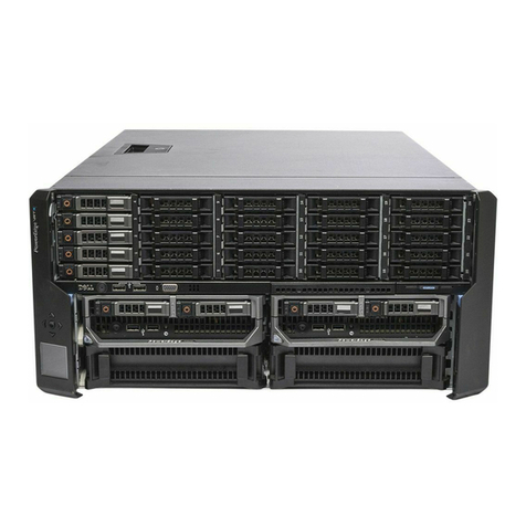
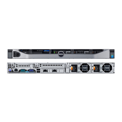
Dell PowerFlex Custom Node R6525 User manual

Dell Technologies PowerFlex Custom Node
R6525
Owner's Guide
October 2021
Rev. 01

Notes, cautions, and warnings
NOTE: A NOTE indicates important information that helps you make better use of your product.
CAUTION: A CAUTION indicates either potential damage to hardware or loss of data and tells you how to avoid
the problem.
WARNING: A WARNING indicates a potential for property damage, personal injury, or death.
© 2021 Dell Inc. or its subsidiaries. All rights reserved. Dell, EMC, and other trademarks are trademarks of Dell Inc. or its subsidiaries. Other
trademarks may be trademarks of their respective owners.

Chapter 1: About this guide........................................................................................................... 5
Chapter 2: System overview..........................................................................................................6
Front view of the system.................................................................................................................................................. 6
Right control panel view.............................................................................................................................................. 8
Left control panel view.................................................................................................................................................9
Rear view of the system.................................................................................................................................................. 10
Inside the system .............................................................................................................................................................. 12
Locating the Express Service Code and Service Tag............................................................................................... 12
System information label.................................................................................................................................................. 12
Rail sizing and rack compatibility matrix.......................................................................................................................15
Chapter 3: Component installation guidelines.............................................................................. 16
Cable routing.......................................................................................................................................................................16
Drive backplane.................................................................................................................................................................. 19
Expansion card installation guidelines.......................................................................................................................... 20
Supported GPU cards...................................................................................................................................................... 29
System memory................................................................................................................................................................. 29
System memory guidelines........................................................................................................................................29
General memory module installation guidelines.....................................................................................................31
Chapter 4: Upgrade kits.............................................................................................................. 35
BOSS S2 kit........................................................................................................................................................................ 35
PCIe Gen 4 NVMe enablement Kit................................................................................................................................36
Serial COM port kit........................................................................................................................................................... 36
Chapter 5: Jumpers and connectors............................................................................................ 37
System board connectors............................................................................................................................................... 37
System board jumper settings....................................................................................................................................... 39
Disabling a forgotten password..................................................................................................................................... 39
Chapter 6: System diagnostics and indicator codes.....................................................................40
Status LED indicators.......................................................................................................................................................40
System health and system ID indicator codes............................................................................................................ 41
iDRAC Quick Sync 2 indicator codes.............................................................................................................................41
iDRAC Direct LED indicator codes................................................................................................................................ 42
LCD panel............................................................................................................................................................................ 42
NIC indicator codes.......................................................................................................................................................... 43
Power supply unit indicator codes................................................................................................................................ 44
Drive indicator codes........................................................................................................................................................45
Using system diagnostics................................................................................................................................................ 46
Dell Embedded System Diagnostics........................................................................................................................46
Chapter 7: Getting help............................................................................................................... 48
Contents
Contents 3

Recycling or End-of-Life service information.............................................................................................................48
Contacting Dell.................................................................................................................................................................. 48
Accessing system information by using QRL..............................................................................................................48
Quick Resource Locator for PowerEdge R6525 system................................................................................... 49
Receiving automated support with SupportAssist ...................................................................................................49
Chapter 8: Documentation resources.......................................................................................... 50
4 Contents

About this guide
This guide provides an overview of the R6525 system, diagnostic tools, and additional component installation guidelines. Use this
guide for information about your system.
1
About this guide 5

System overview
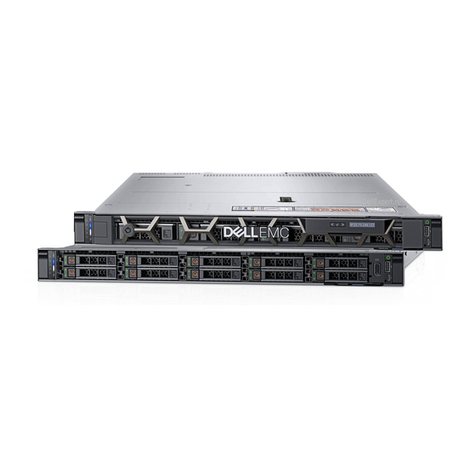
The Dell Technologies PowerFlex custom node R6525 system is a 1U rack server that supports:
●Two AMD EPYCTM 7002 or 7003 series processors
●32 DIMM slots
●Two redundant AC or DC power supply units
●Up to 8 x 2.5-inch, or 10 x 2.5-inch SAS, SATA, or NVMe drives.
NOTE: For more information about how to hot swap NVMe PCIe SSD U.2 devices, see the Dell Express Flash NVMe
PCIe SSD User's Guide at https://www.dell.com/support. Look for Data Center Infrastructure > Storage Adapters &
Controllers > Dell PowerEdge Express Flash NVMe PCIe SSD > Documentation > Manuals and Documents.
NOTE: All instances of SAS, SATA drives, PCIe SSDs, and NVMe are referred to as drives in this document, unless specified
otherwise.
WARNING: Consumer-grade GPUs should not be installed or used in Enterprise Server products.
For more information about supported drives, see the www.dell.com/poweredgemanuals section.
For more information, see the Dell Technologies PowerFlex custom node R6525 technical specifications on the product
documentation page.
Front view of the system
Figure 1. Front view of the 10 x 2.5-inch drive system
Table 1. Features available on the front of the system
Item Ports, panels, and
slots
Icon Description
1 Left control panel N/A Contains the system health, system ID, status LED, and the
iDRAC Quick Sync 2 (wireless) indicator.
NOTE: The iDRAC Quick Sync 2 indicator is available only
on certain configurations.
●Status LED: Enables you to identify any failed hardware
components. There are up to five status LEDs and an overall
system health LED (Chassis health and system ID) bar. For
more information, see the Status LED indicators section.
●Quick Sync 2 (wireless): Indicates a Quick Sync enabled
system. The Quick Sync feature is optional. This feature
allows management of the system by using mobile devices
that are called as OpenManage Mobile (OMM) feature.
Using iDRAC Quick Sync 2 with OpenManage Mobile (OMM)
aggregates hardware or firmware inventory and various
system level diagnostic and error information that can be
2
6 System overview

Table 1. Features available on the front of the system (continued)
Item Ports, panels, and
slots
Icon Description
used in troubleshooting the system. For more information,
see the Integrated Dell Remote Access Controller User's
Guide available at https://www.dell.com/idracmanuals
2 VGA port Enables you to connect a display device to the system.
3 Right control panel N/A Contains the power button, USB port, iDRAC Direct micro port,
and the iDRAC Direct status LED.
4 Information tag The Information tag is a slide-out label panel that contains
system information such as Service Tag, NIC, MAC address,
and so on. If you have opted for the secure default access
to iDRAC, the Information tag also contains the iDRAC secure
default password.
5 Drive (10) N/A Enables you to install drives that are supported on your system.
Figure 2. Front view of the 8 x 2.5-inch drive system
Table 2. Features available on the front of the system
Item Ports, panels, and
slots
Icon Description
1 Left control panel N/A Contains the system health, system ID, status LED, and the
iDRAC Quick Sync 2 (wireless) indicator.
NOTE: The iDRAC Quick Sync 2 indicator is available only
on certain configurations.
●Status LED: Enables you to identify any failed hardware
components. There are up to five status LEDs and an overall
system health LED (Chassis health and system ID) bar. For
more information, see the Status LED indicators section.
●Quick Sync 2 (wireless): Indicates a Quick Sync enabled
system. The Quick Sync feature is optional. This feature
allows management of the system by using mobile devices
that are called as OpenManage Mobile (OMM) feature.
Using iDRAC Quick Sync 2 with OpenManage Mobile (OMM)
aggregates hardware or firmware inventory and various
system level diagnostic and error information that can be
used in troubleshooting the system. For more information,
see the Integrated Dell Remote Access Controller User's
Guide available at https://www.dell.com/idracmanuals
2 Drive (8) N/A Enables you to install drives that are supported on your system.
3 Right control panel N/A Contains the power button, USB port, iDRAC Direct micro port,
and the iDRAC Direct status LED.
4 VGA port Enables you to connect a display device to the system.
System overview 7

Table 2. Features available on the front of the system (continued)
Item Ports, panels, and
slots
Icon Description
5 Information tag The Information tag is a slide-out label panel that contains
system information such as Service Tag, NIC, MAC address,
and so on. If you have opted for the secure default access
to iDRAC, the Information tag also contains the iDRAC secure
default password.
Right control panel view
Figure 3. Right control panel
Table 3. Right control panel
Item Indicator or button Icon Description
1 Power button Indicates if the system is powered on or off. Press the power button to
manually power on or off the system.
NOTE: Press the power button to gracefully shut down the ACPI-
compliant operating system.
2USB 2.0-compliant port The USB port is a 4-pin connector and 2.0-compliant. This port enables
you to connect USB devices to the system.
3iDRAC Direct LED
indicator
N/A The iDRAC Direct LED indicator lights up to indicate that the iDRAC Direct
port is actively connected to a device.
4iDRAC Direct port (Micro-
AB USB)
The iDRAC Direct port (Micro-AB USB) enables you to access
the iDRAC Direct Micro-AB features. For more information, see the
Integrated Dell Remote Access Controller User's Guide available at
https://www.dell.com/idracmanuals .
NOTE: You can configure iDRAC Direct by using a USB to micro USB
(type AB) cable, which you can connect to your laptop or tablet. Cable
length should not exceed 3 feet (0.91 meters). Performance could be
affected by cable quality.
8 System overview

Left control panel view
Figure 4. Left control panel without optional iDRAC Quick Sync 2.0 indicator
Figure 5. Left control panel with optional iDRAC Quick Sync 2.0 indicator
Table 4. Left control panel
Item Indicator, button, or
connector
Icon Description
1 Status LED indicators N/A Indicates the status of the system. For more information, see Status LED
indicators.
2System health and system ID
indicator
Indicates the system health. For more information, see System diagnostics
and indicator codes.
3iDRAC Quick Sync 2 wireless
indicator (optional)
Indicates whether the iDRAC Quick Sync 2 wireless option is activated.
The Quick Sync 2 feature allows management of the system using mobile
devices. This feature aggregates hardware/firmware inventory and various
system level diagnostic/error information that can be used in troubleshooting
the system. You can access system inventory, Dell Lifecycle Controller logs
or system logs, system health status, and also configure iDRAC, BIOS,
and networking parameters. You can also launch the virtual Keyboard,
Video, and Mouse (KVM) viewer and virtual Kernel-based Virtual Machine
(KVM), on a supported mobile device. For more information, see the
Integrated Dell Remote Access Controller User's Guide at www.dell.com/
poweredgemanuals.
NOTE: For more information about the indicator codes, see System diagnostics and indicator codes.
System overview 9

Rear view of the system
Figure 6. Rear view of the 10 x 2.5-inch drive system
Table 5. Rear view of the system
Item Ports, panels, or slots Icon Description
1 Power supply unit (PSU 1) Indicates the PSU.
2PCIe expansion card riser
(slot 1)
N/A The expansion card riser enables you to connect PCI
Express expansion cards.
3PCIe expansion card riser
(slot 2)
N/A The expansion card riser enables you to connect PCI
Express expansion cards.
4 USB 2.0 port (1) This port is USB 2.0-compliant.
5 Power supply unit (PSU
2)
Indicates the PSU.
6VGA port Enables you to connect a display device to the system. .
7 USB 3.0 port (1) This port is USB 3.0-compliant.
8 iDRAC dedicated port Enables you to remotely access iDRAC. For more
information, see the iDRAC User’s Guide at www.dell.com/
poweredgemanuals.
9 System identification
button
Press the system ID button:
●To locate a particular system within a rack.
●To turn the system ID on or off.
To reset iDRAC, press and hold the button for more than 16
seconds.
NOTE:
●To reset iDRAC using system ID, ensure that the
system ID button is enabled in the iDRAC setup.
●If the system stops responding during POST, press
and hold the system ID button (for more than 5
seconds) to enter the BIOS progress mode.
10 OCP NIC port (optional) N/A This port supports OCP 3.0. The NIC ports are integrated
on the OCP card, which is connected to the system board.
11 NIC port (2) The NIC ports are embedded on the LOM card that is
connected to the system board.
12 BOSS S2 card (optional) N/A This slot supports the BOSS S2 module.
10 System overview

Figure 7. Rear view of the 8 x 2.5-inch drive system.
Table 6. Rear view of the system
Item Ports, panels, or slots Icon Description
1 Power supply unit (PSU 1) Indicates the PSU.
2PCIe expansion card riser
(slot 1)
N/A The expansion card riser enables you to connect PCI
Express expansion cards.
3PCIe expansion card riser
(slot 2)
N/A The expansion card riser enables you to connect PCI
Express expansion cards.
4 USB 2.0 port (1) This port is USB 2.0-compliant.
5 PCIe expansion card riser
(slot 3)
N/A The expansion card riser enables you to connect PCI
Express expansion cards.
6 Power supply unit (PSU
2)
Indicates the PSU.
7VGA port Enables you to connect a display device to the system.
8 USB 3.0 port (1) This port is USB 3.0-compliant.
9 iDRAC dedicated port Enables you to remotely access iDRAC. For more
information, see the iDRAC User’s Guide at www.dell.com/
poweredgemanuals.
10 System identification
button
Press the system ID button:
●To locate a particular system within a rack.
●To turn the system ID on or off.
To reset iDRAC, press and hold the button for more than 16
seconds.
NOTE:
●To reset iDRAC using system ID, ensure that the
system ID button is enabled in the iDRAC setup.
●If the system stops responding during POST, press
and hold the system ID button (for more than 5
seconds) to enter the BIOS progress mode.
11 OCP NIC port (optional) N/A This port supports OCP 3.0. The NIC ports are integrated
on the OCP card, which is connected to the system board.
12 NIC port (2) The NIC ports are embedded on the LOM card that is
connected to the system board.
13 BOSS S2 card (optional) N/A This slot supports the BOSS S2 module.
System overview 11

Inside the system
Figure 8. Inside the system
1. Drive backplane 2. Rear mounting front PERC module
3. Dual fan module (4) 4. System board
5. Memory DIMM socket for processor 2 (B1) 6. Heat sink for processor 2
7. Riser 3 8. Intrusion switch
9. Power supply unit (PSU 2) 10. Power supply unit (PSU 1)
11. IDSDM/Internal USB card port 12. BOSS slot
13. Riser 2 14. Heat sink for processor 1
15. Memory DIMM socket for processor 1 (A1) 16. xGMI cables
Locating the Express Service Code and Service Tag
The unique Express Service Code and Service Tag are used to identify the system.
System information label
The system information label is located on the back side of the system cover.
12 System overview

Figure 9. Service information
System overview 13

Figure 10. Memory information and system board connectors
14 System overview

Figure 11. LED behavior, configuration and layout, express service tag
Rail sizing and rack compatibility matrix
For specific information about the rail solutions compatible with your system, see the Dell EMC Enterprise Systems
Rail Sizing and Rack Compatibility Matrix available at https://i.dell.com/sites/csdocuments/Business_solutions_engineering-
Docs_Documents/en/rail-rack-matrix.pdf.
The document provides the information that is listed below:
●Specific details about rail types and their functionalities.
●Rail adjustability range for various types of rack mounting flanges.
●Rail depth with and without cable management accessories.
●Types of racks supported for various types of rack mounting flanges.
System overview 15

Component installation guidelines
This section describes additional guidelines required for installing the drive backplane, expansion card risers, memory modules,
and other system components.
For detailed component installation instructions, see the Dell Technologies PowerFlex Custom Node R6525 Field Replaceable
Unit Guide.
Cable routing
Figure 12. 10 x 2.5-inch SAS XGMI
3
16 Component installation guidelines

Figure 13. 10 x 2.5-inch Universal backplane
Figure 14. 10 x 2.5-inch NVMe backplane (48 mode)
Component installation guidelines 17

Figure 15. 10 X 2.5-inch NVMe (64 mode)
Figure 16. 10 X 2.5-inch SAS with 2 x 2.5-inch SAS rear drive
18 Component installation guidelines

Figure 17. 10 x 2.5-inch SAS with 2 x 2.5-inch NVMe drive
Figure 18. 8 x 2.5- inch NVMe RAID
Drive backplane
Depending on your system configuration, the drive backplanes supported are listed here:
Table 7. Supported backplane options
System Supported drive options
PowerFlex custom node R6525 2.5-inch (x8) SAS or SATA backplane
Component installation guidelines 19

Table 7. Supported backplane options (continued)
System Supported drive options
2.5-inch (x10) SAS, SATA or NVMe backplane
2.5-inch (x2) SAS/SATA/NVME rear backplane
Figure 19. 8 x 2.5-inch drive backplane
1. BP_PWR_1 (backplane power and signal cable to system board)
Figure 20. 10 x 2.5-inch drive backplane
1. DST_SA2 (backplane to front PERC) 2. DST_PB2 (PCIe/NVMe connector)
3. DST_PA2 (PCIe/NVMe connector) 4. DST_SA1 (PERC to backplane)
5. BP_PWR_1 (backplane power and signal cable to system
board)
6. DST_PA1 (PCIe/NVMe connector)
7. DST_PB1 (PCIe/NVMe connector) 8. DST_PA3 (PCIe/NVMe connector)
Expansion card installation guidelines
The following table describes the supported expansion cards:
Table 8. Expansion card riser configurations
Expansion card riser PCIe slots on the
riser
Processor
connection
Height Length Slot
width
R1a (Riser 1) Slot 1 Processor 1 Full Height 3/4th Length x16
R2a (Riser 2) Slot 1 Processor 1 Low Profile Half Length x16
Slot 2 Processor 2 Low Profile Half Length x16
R3a (Riser 3) Slot 3 Processor 2 Low Profile Half Length x16
R4c + R4d (Riser 4) Slot 2 Processor 2 Full Height 3/4th Length x16
NOTE: The expansion-card slots are not hot-swappable.
The following table provides guidelines for installing expansion cards to ensure proper cooling and mechanical fit. The expansion
cards with the highest priority should be installed first using the slot priority indicated. All the other expansion cards should be
installed in the card priority and slot priority order.
20 Component installation guidelines
Table of contents
Other Dell Server manuals

Dell
Dell PowerEdge T630 User manual

Dell
Dell DL4300 User manual

Dell
Dell PowerEdge R300 Quick start guide

Dell
Dell DX6000G User manual

Dell
Dell PowerEdge R210 II User manual

Dell
Dell E43S001 User manual

Dell
Dell PowerEdge 2300 User manual

Dell
Dell PS4000X User manual

Dell
Dell PowerEdge R820 User manual

Dell
Dell PowerEdge T430 User manual

Dell
Dell Wyse ThinOS T10 User manual

Dell
Dell PowerEdge 4350 User manual

Dell
Dell PowerEdge T320 Quick start guide

Dell
Dell EMC PowerEdge R440 Manual

Dell
Dell Wyse ThinOS T10 User manual

Dell
Dell PowerEdge 2600 User manual

Dell
Dell PowerEdge C8000 Datasheet

Dell
Dell PowerEdge 2410 User manual

Dell
Dell DR4300 User manual

Dell
Dell POWEREDGE 1900 Technical manual