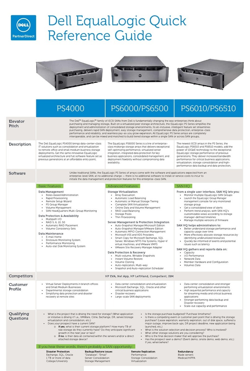
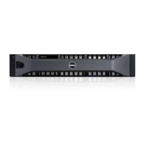
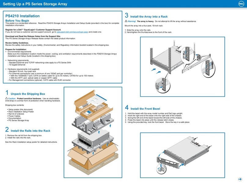
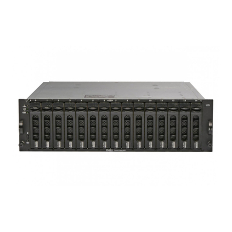
Dell EqualLogic PS4210 Assembly instructions

Dell EqualLogic PS4210 Storage Arrays
Installation and Setup Guide


Dell EqualLogic PS4210 Storage Arrays
Installation and Setup Guide
Version 1.0
Regulatory Model Series E03J and E04J

©Copyright2014DellInc.Allrightsreserved.
Dell™andEqualLogic®aretrademarksofDellInc.Alltrademarksandregisteredtrademarksmentionedherein
arethepropertyoftheirrespectiveowners.
Informationinthisdocumentissubjecttochangewithoutnotice.
ReproductionofthismaterialinanymannerwhatsoeverwithoutthewrittenpermissionofDellisstrictly
forbidden.
Published:October2014
PartNumber:M40C6-A00

Table of Contents
Preface v
1 Understanding the Array Installation Procedure 1
2 Rack Mounting the Array 3
BeforeYouBegin 3
ProtectingHardware 4
StepsforMountinganArrayinaRack 6
3 Connecting the Array Cables 9
NetworkRequirementsandRecommendations 9
MinimumandRecommendedCableConfigurations 10
ConnectandSecurethePowerCables 11
ConnecttheArraytotheNetwork 12
SetUpaSerialConnectiontotheArray 13
4 Software Configuration 17
ChooseaConfigurationMethod 17
CollectConfigurationInformation 17
StarttheSoftwareConfiguration 18
SettheMemberRAIDPolicy 21
5 Storage Allocation 23
CreateaVolume 23
ConnectaComputertoaVolume 27
6 Where to Go After Setting Up a Group 29
CommonGroupCustomizationTasks 29
7 Other Information You Might Need 31
NOMInformation(MexicoOnly) 31
Index 35
iii

Installation and Setup Guide Table of Contents
iv

Preface
Dell™EqualLogic®PSSeriesarraysoptimizeresourcesbyautomatingcapacity,performance,andnetwork
loadbalancing.Additionally,PSSeriesarraysofferall-inclusivearraymanagementsoftwareandfirmware
updates.DellEqualLogicFSSeriesappliances,combinedwithPSSeriesarrays,offerahigh-performance,high-
availability,scalableNASsolution.
Audience
Theinformationinthisguideisintendedforhardwareadministrators.Administratorsarenotrequiredtohave
extensivenetworkorstoragesystemexperience.However,itishelpfultounderstand:
• Basicnetworkingconcepts
• Currentnetworkenvironment
• Userdiskstoragerequirements
• RAIDconfigurations
• Diskstoragemanagement
Note: AlthoughthismanualprovidesexamplesofusingPSSeriesarraysinsomecommonnetwork
configurations,detailedinformationaboutsettingupanetworkisbeyonditsscope.
Related Documentation
FordetailedinformationaboutPSSeriesarrays,groups,volumes,arraysoftware,andhostsoftware:
1. LogintotheDellEqualLogicsupportsite(eqlsupport.dell.com).
2. SelectDownloads.
3. Fromthedrop-downlist,choosePS Series Firmware.
4. UnderRecommendedPSSeriesFirmware,selecttherequiredversion.Thelinktothedownloadpage
appears.
5. ClicktheDownloadpagelink.
6. ScrolldowntoDocumentation.
Dell Online Services
YoucanlearnaboutDellproductsandservicesbyvisitingdell.com(ortheURLspecifiedinanyDellproduct
information).
TolearnmoreaboutDellEqualLogicproductsandnewreleases,visittheDellEqualLogicTechCentersite:
delltechcenter.com/page/EqualLogic.Hereyoucanalsoseearticles,demos,onlinediscussions,andmoredetails
aboutthebenefitsofourproductfamily.
Technical Support and Customer Service
Dell’ssupportserviceisavailabletoansweryourquestionsaboutPSSeriesSANarrays.IfyouhaveanExpress
ServiceCode,haveitreadywhenyoucall.ThecodehelpsDell’sautomated-supporttelephonesystemdirect
yourcallmoreefficiently.
v
Installation and Setup Guide Preface
Contacting Dell
Dellprovidesseveralonlineandtelephone-basedsupportandserviceoptions.Availabilityvariesbycountryand
product,andsomeservicesmightnotbeavailableinyourarea.
TocontactDellEqualLogicTechnicalSupportbyphone,ifyouarelocatedintheUnitedStates,call800-945-
3355.ForalistingofInternationalDellEqualLogicsupportnumbers,visitdell.com/support/home.Fromthis
website,selectyourcountryfromthedrop-downlistintheupperleftcornerofthescreen.Ifyoudonothave
accesstoanInternetconnection,contactinformationisprintedonyourinvoice,packingslip,bill,orDellproduct
catalog.
UsethefollowingproceduretoregisterforanEqualLogiccustomersupportaccount,tologcasesviatheweb,
andtoobtainsoftwareupdates,furtherdocumentationandresources.
1. Visiteqlsupport.dell.comortheDellsupportURLspecifiedininformationprovidedwiththeDellproduct.
2. Selecttherequiredservice.ClicktheContact Uslink,orselecttheDellsupportservicefromthelistof
servicesprovided.
3. ChooseyourpreferredmethodofcontactingDellsupport,suchase-mailortelephone.
Warranty Information
ThePS4210arraywarrantyisincludedintheshippingbox.Forinformationaboutregisteringawarranty,visit
https://eqlsupport.dell.com/utility/form.aspx?source=warranty.
Notes, Cautions, and Warnings Symbols
ANOTEsymbolindicatesimportantinformationthathelpsyoumakebetteruseofyourhardwareorsoftware.
ACAUTIONsymbolindicatespotentialdamagetohardwareorlossofdataifinstructionsarenotfollowed.
AWARNINGsymbolindicatesapotentialforpropertydamage,personalinjury,ordeath.
Further Information
Forbasicstoragearrayinformation,maintenanceinformation,andtroubleshootinginformation,refertothe
PS4210HardwareOwner'sManual.
vi

1 Understanding the Array Installation Procedure
TosetupyourarrayandstartusingtheiSCSISANarray,followthesesteps:
1. Installthearrayinarack.SeeRack Mounting the Array on page 3.
2. Connectthearraytopowerandthenetwork.SeeConnect and Secure the Power Cables on page 11and
Connect the Array to the Network on page 12.
3. ConfigurethePSSeriessoftware.First,initializeanarraytomakeitaccessibleonthenetwork.Then,either
createagroupwiththearrayasthefirstgroupmemberoraddthearraytoanexistinggroup.Whenyou
expandagroup,capacityandperformanceincreaseautomatically.SeeChoose a Configuration Method on
page 17.
4. StartusingtheiSCSISANarray.Allocategroupstoragespacetousersandapplicationsbycreating
volumes.AvolumeappearsonthenetworkasaniSCSItarget.Useacomputer’siSCSIinitiatortoconnect
toavolume.Afteryouconnecttoavolume,itappearsasaregulardiskonthecomputer.SeeStorage
Allocation on page 23.
Aftergettingstarted,youcancustomizethegroupanduseitsmoreadvancedfeatures.SeeWhere to Go After
Setting Up a Group on page 29.
1

PS4210 Hardware Owner's Manual 1 Understanding the Array Installation Procedure
2

2 Rack Mounting the Array
Forproperoperation,aPSSeriesstoragearraymustbeproperlyinstalledinarack.Thissection
containsgeneralelectrostatic,safety,network,andinstallationinformationforPSSeriesarrays.
Afterinstallingthearrayinarack,connectthepowerandnetworkcables,asdescribedin
Chapter 3.
Before You Begin
Beforeinstallingthearray:
• RegisterforaDell™EqualLogic®CustomerSupportAccount.Ifyoudonothavea
customerservicesupportaccount,gotoeqlsupport.dell.comandcreateone.
• DownloadandreadtheReleaseNotesfromtheSupportSite.ThePS Series Storage Arrays
Release Notescontainthelatestproductinformation.
• Readtheinstallationsafetyprecautions.SeeInstallation Safety Precautions on page 3.
• Makesuretherackmeetstherackrequirements.SeeRack Requirements on page 3.
• Makesurethearrayandinstallationlocationmeettheenvironmentalrequirements.See
Environmental Requirements on page 4.
• Unpacktherailkit(ifordered)andmakesureyouhaveallthenecessarypartsandtools.
Therailkitislocatedinthearrayshippingbox.Youmustsupplyyourowntools.See
Shipping Box Contents and Required Hardware on page 5.
Installation Safety Precautions
Followthesesafetyprecautions:
• Dellrecommendsthatonlyindividualswithrack-mountingexperienceinstallanarrayina
rack.
• Makesurethearrayisfullygroundedatalltimestopreventdamagefromelectrostatic
discharge.
• Whenhandlingthearrayhardware,youmustusetheelectrostaticwristguardshippedwith
thearrayorasimilarformofprotection.
• Youneedatleasttwopeopletoliftthearraychassisfromtheshippingbox.
Rack Requirements
Therackandthearrayinstallationmustmeetthefollowingrequirements:
• Useanindustry-standard,EIA-310-Dcompliant,four-post19-inchrackwithuniversal
squareholeorunthreadedroundholespacing.
• Therackisratedfor540kg(1200pounds)staticloadorgreater.
• Theminimumrackdepthis100cm(40inches)fromthefrontoftheracktotherearofthe
rack.
3

• FortheReadyRails™IIrailkits,thedistancebetweentheoutsidesurfacesofthefrontand
rearrackposts(themountingsurfaces)canrangefrom595mmto914mm(23.4”to36.0”)
forsquare-holeracks,581mmto907mm(22.9”to35.7”)forround-holeracks,and595mm
to929mm(23.4”to36.6”)forthreaded-holeracks.
• Therackissecuredtothefloorforaddedstability.
• Loadarackwitharraysfromthebottomtothetop.
• Thereisatleast4.1cm(1.6inches)betweentherackdoorandthefrontofthearrayto
accommodatethearrayfrontbezel.
• Therack(withinstalledarrays)meetsthesafetyrequirementsofUL60950-1andIEC
60950-1,availableatulstandardsinfonet.ul.com/scopes/scopes.asp?fn=60950-1.html.
• Mountthearrayinahorizontalorientationoryouwillvoidyourarraywarrantyandsupport
contract.
Environmental Requirements
Theracklocationmustmeetthefollowingenvironmentalrequirements:
• Thepowersourcecansupplyavoltagerangeof100Vto240VAC.
• Thepowersourcehassufficientelectricaloverloadprotection:
InNorthAmerica,connectthearraytoasourceofpowerwithover-currentprotection
providedbyadoublepole20Aorlessdevice(UL489circuitbreakers).
InEurope,theover-currentprotectionmustbeprovidedbya20Aorlessdevice(IEC
circuitbreakers).
• Thereissufficientspaceforairflowinfrontofandbehindthearray.
• Thelocationisproperlyvented.
• YourenvironmentsupportsalloftherequirementslistedintheTechnical Specifications on
page 31.
Protecting Hardware
ProtectyourPSSeriesarrayfromelectrostaticdischarge.Whenhandlingarrayhardware,usean
electrostaticwriststraporasimilarformofprotection.Touseawriststrap:
1. Connectthesteelsnaponthecoilcordtothestudontheelasticband.SeeFigure1.
Figure 1: Using an Electrostatic Wrist Strap
2. Fitthebandtightlyaroundyourwrist.
4
PS4210 Installation Guide 2 Rack Mounting the Array

PS4210 Installation Guide 2 Rack Mounting the Array
3. Connectthebandtoground.Youcaneitherplugthebananaconnectorintoamatching
groundedreceptacle,orattachittothematchingalligatorclipandconnectthecliptoa
groundeddevice.ExamplesofanappropriategroundwouldbeanESDmatorthemetal
frameofagroundedpieceofequipment.
Shipping Box Contents and Required Hardware
Makesureyouhavealltheitemssuppliedintheshippingbox,describedinTable1.Youmust
provideadditionalhardwarethatisspecifictoyourenvironmentandnotincludedintheshipping
box.SeeTable2.
Table 1: Shipping Box Contents
Component Description
PSSeriesArray
• TwoType19controlmodules
• Twopowersupplyandcoolingmodules
• Upto242.5-inch10Kor123.5-inch7.2Kserial-attachedSCSI(SAS,
NearlineSAS[NL-SAS],orSolidState(SSD)drives,dependingonthe
modelsuffix
Bezel Thebezelmountstothefrontofthearray.Thebezelidentifiesthearray
modelandprotectsthedrivesfromunauthorizedoraccidentalremoval.
Powercables
Connectsanarraypowersupplytopowersources.Ifpowercablesarenot
includedintheshippingbox,contactyourPSSeriesarraysupportprovideror
reseller.
Oneortwoserial
cables
Createsaserialconnectionbetweenanarrayandaconsoleorterminal
emulator.Usethecabletorunthesetuputilityifthereisnonetworkaccess
tothearrayorgroup.
Documentation
Thefollowingdocumentationisincludedintheshippingbox:
• Setupposter
• InstallationandSetupGuide(thisdocument)
• License,regulatory,andwarrantyinformation
• Safety,Environmental,andRegulatoryInformationbooklet
Table 2: Additional Hardware Required (Not Included)
Component Description
Standard19-in.
four-postrack
Provideseasyaccesstoarraysandotherhardwareinyourcomputing
environment.
10/100Mbps
Ethernetcables
Forusewithadedicatedmanagementnetwork.ConnectstheManagementporton
thearraytoa10/100Mbpsnetworkswitch.UseCategory5EorCategory6cables
withRJ45connectors.UseCategory5cablesonlyiftheymeettheTIA/EIA
TSB95standard.
Networkswitch
Connectsdevices(array)toanetwork.Multipleswitchesarerecommended.
Switchprovides10GBASE-Tinterfacestousethe10GBASE-Tport,oran
SFP+switchtousetheSFP+port.
CAT6orCAT6A
cables
For10GBASE-Tport,useCategory6(orbetter)cableforupto55meters.Use
Category6Acableforupto100meters.
Opticalorcopper
cables ForSFP+port,useopticalcableorcopperSFP+cable.
5

Optional Hardware
Youcanoptionallyuseanuninterruptiblepowersupplysystem(UPS)toprovideahighly
availablesourceofpowertoanarray.EachUPS(notincluded)shouldbeonadifferentcircuit
andmustprovidethecorrecttypeofvoltageforanadequateamountoftime.
Steps for Mounting an Array in a Rack
Tomountanarrayinarack,followthesesteps:
1. Determinewheretoplacethemountingrailsintherack.
2. Attachthemountingrailstotherack.
3. Slidethechassisintotherack.
4. Attachthechassistothefrontofthemountingrails.
5. Installthebezel.
Thesestepsaredescribedindetailinthefollowingsections.
Determine Where to Place the Mounting Rails in the
Rack
Makesurethereisenoughspaceintherackforthechassis.Inastandardrack,a2Uchassis
willspansixholes.
Installing the Rails and Array in a Rack
Installtherailsintherackfollowingthesafetyinstructionsandtherackinstallationinstructions
providedwithyourrailkit.
Ifinstalledinaclosedormulti-unitrackassembly,theoperatingtemperatureoftherack
environmentmightbegreaterthanroomambient.Therefore,makesureyouinstallthearrayin
anenvironmentcompatiblewiththemaximumtemperaturespecifiedbythemanufacturer.For
moreinformation,seeTechnical Specifications on page 31.
Slide the Array into the Rack
SlidethearrayintotherackasshowninFigure2.
6
PS4210 Installation Guide 2 Rack Mounting the Array

PS4210 Installation Guide 2 Rack Mounting the Array
Figure 2: Installing the Array Into the Rack
Figure3showsthefrontviewofthe3.5-inchdrivearray.
Figure 3: 3.5-Inch Drive Array - Front View (Without Bezel)
Figure4showsthefrontviewofthe2.5-inchdrivearray.
Figure 4: 2.5-Inch Drive Array - Front View (Without Bezel)
Withassistance,liftthearray,keepingthearraylevel,andslideitontothemountingrailsuntil
thearrayengages.
Attach the Array to the Mounting Rails
Makesurethearraycaptivefastenersonthefrontofthearraylineupwiththethreadedholeson
thefrontofthemountingrails,andmanuallysecurethecaptivefastenerstotherails.
Note: Donotovertightenthethumbscrews.
7

Installing the Bezel
Thestepsforinstallingthebezelarethesameforallarraymodels:
1. Hooktherightendofthebezelontotherightsideofthechassis.
2. Swingtheleftendofthebezeltowardtheleftsideofthechassis.
3. Pressthebezelintoplaceuntilthereleaselatchcloses.
4. Usingthekeyprovided,lockthebezelandstorethekeyinasafeplaceasshowninFigure
5.
Figure 5: Installing the Bezel
8
PS4210 Installation Guide 2 Rack Mounting the Array

3 Connecting the Array Cables
Afteryouinstallthearrayinarack,youmustconnectthenetworkandpowercablesand,
optionally,theserialcables.
First,reviewthenetworkrecommendationsinMinimum and Recommended Cable
Configurations on page 10.
Thefollowinglistdescribesthegeneralstepsforconnectingthearraytopowerandthenetwork:
1. Connectthepowercables.Donotturnonpowertothearrayatthistime.SeeConnect and
Secure the Power Cables on page 11.
2. Connectthearraytothenetwork.SeeConnect the Array to the Network on page 12.
3. Turnonpowertothearray.SeeTurning On the Array on page 12.
Thefollowingsectionsdescribethesestepsindetail.Aftercompletingthesteps,seeSoftware
Configuration on page 17.
Network Requirements and Recommendations
TheminimumnetworkconfigurationforaPSSeriesarrayconsistsofaconnectionbetween
Ethernet0oneachcontrolmoduleandacomputerconnectedtoanetworkswitch.Toincrease
performanceandavailability,configuremultiplenetworkinterfacesonanarrayandconnect
themtomultipleswitches.
NetworkrecommendationsaredescribedinTable3.Inaddition,alltheusualrulesforproper
networkconfigurationapplytoPSSeriesarrays.Formoreinformationaboutnetwork
requirements,seetheDellEqualLogicConfigurationGuideontheDellTechCenterwebsiteat
en.community.dell.com/techcenter/storage/w/wiki/2639.equallogic-configuration-guide.aspx.
Generalnetworkconfigurationisbeyondthescopeofthismanual.
Table 3: Network Recommendations
Recommendation Description
Switched10GbE
network
Connectarraysandcomputerstoaswitchednetworkandensurethatall
networkconnectionsbetweencomputersandarraysare10GbE.
UseopticalcableswithopticalSFP+plug-inmodules,orcoppercableswith
integratedSFP+modules.10GBASE-TrequiresCat6minimally,butCat6Ais
recommended.
Requiresaswitchwith10GBASE-Tinterfacestousethe10GBASE-Tport,or
anSFP+switchtousetheSFP+port.
Multiplenetwork
connectionsto
differentnetwork
switches
Forincreasedbandwidthandavailability,connecteachcontrolmoduletotwo
differentswitches.
Theswitchesmustbeconnectedusinginterswitchlinksorbystacking
capability.ThelinksmusthavesufficientbandwidthtohandletheiSCSI
traffic.ReviewtheEqualLogicConfigurationGuideforinterswitchlinksizing
recommendations.
Afterconnectingthenetworkinterfaces,usetheGroupManagerGUIorCLIto
assignanIPaddress,netmask,andgatewayaddresstoeachinterface.
9

Recommendation Description
Management
network(optional)
Connectthemanagementportsonbothcontrolmodulestoa10/100Mbps
networkswitchtokeepmanagementtrafficseparatefromiSCSItraffic.
Accesstothegroup
IPaddress(Hosts)
Inamulti-subnetgroup,eachconfigurednetworkinterfaceshouldhaveaccess
tothesubnetonwhichthegroupIPaddressresides.
Forreplication,a
reliable,adequately
sizednetworklink
Foreffectiveandpredictablereplication,thenetworklinkbetweentheprimary
andsecondarygroupsmustbereliableandprovidesufficientbandwidthfor
copyingdata.
Useofspanning-tree
protocol
Ifpossible,donotuseSpanningTreeProtocol(STP)onswitchportsthat
connectendnodes(iSCSIinitiatorsorarraynetworkinterfaces).
IfyoumustuseSTPorRSTP(STPispreferable),enabletheportsettings
(availableonsomeswitches)thatlettheportimmediatelytransitionintoSTP
forwardingstateuponlinkup.Thisfunctionalitycanreducenetwork
interruptionsthatoccurwhendevicesrestart,andshouldbeenabledonlyon
switchportsthatconnectendnodes.
YoucanuseSTPforasingle-cableconnectionbetweenswitchesandtrunking
formulticableconnectionsbetweenswitches.
VLANs TouseDCB(DataCenterBridging),configureswitchestouseVLANsto
separateiSCSISANtrafficfromothernetworktraffic.
DCB
YoumusthaveVLANsenabled.RefertotheDell EqualLogic Group Manager
Administrator's Manual,andtheDellEqualLogic Group Manager
CLI Reference GuideformoreinformationaboutDCB.
Minimum and Recommended Cable
Configurations
Foradualcontrolmodulearray,therecommendedconfigurationistoconnectnetworkcablesto
Ethernet0onbothcontrolmodules,andconnecteachcontrolmoduletoanetworkswitch.
Forhighperformanceandavailability,distributetheconnectionsacrossmultiplenetwork
switches.
Theswitchesmustbeconnectedwithinterswitchlinksthathavesufficientbandwidthtohandle
theiSCSItraffic,orbystackingcapability.Dellrecommendsusingstackingconfigurations
whereverpossible.
Figure6illustratestherecommendednetworkconfigurationalternatives.
Note: DelldoesnotrecommendconnectingboththeSFP+and10GBASE-TEthernetportsat
thesametime.
10
PS4210 Installation Guide 3 Connecting the Array Cables

PS4210 Installation Guide 3 Connecting the Array Cables
Figure 6: Recommended Network Configurations
Connect and Secure the Power Cables
Obtainthepowercablesthatwereshippedwiththearray.Ifthearraywasnotshippedwith
powercables,contactyourPSSeriessupportproviderorresellerforpowercableinformation.
1. MakesurethatthepowerswitchisintheOFF(O)positionbeforeconnectingthepower
cables.
2. Connectthepowercablestothepowersuppliesasshownin.
3. Securethepowercablestothesystem:
a. Securethepowercablesfirmlytothebracketnexttothesystempowerreceptacle
usingtheprovidedhook-and-loopstrap.
b. Makesurethestrapistightlyboundtothebracketanchorpoint(removeanyslack).
c. Biasthepowercabletowardthestrapandwrapthestraptightlyaroundthecable
againsttheshoulderofthepowercableconnector.
4. Attachthepowercablestoapowersource:
11

– Plugthepowercablesintoagroundedelectricaloutletoraseparatepowersourcesuch
asanuninterruptedpowersupply(UPS)orapowerdistributionunit(PDU).Thebottom
LEDofthepowersupplywillbeilluminatedgreen(indicatingpowerispresent)when
powercablesareconnected.
– EachUPS(notincluded)shouldbeonadifferentcircuitandmustprovidethecorrect
typeofvoltageforanadequateamountoftime.
– Alternately,connectonepowersupplyandcoolingmoduletoaUPSsystemandconnect
theothermoduletoadifferentsourceofpower.
Caution: Donotturnonpowertothearrayyet.
Figure 7: Connecting the AC Power Cables
Connect the Array to the Network
ThePS4210arraymodelincludestwoType19controlmodules.EachType19controlmodule
includestwo10Gbase-Tportsandtwo10GbeSFP+ports.Ofeachpair,oneislabeledEthernet
0andtheotherislabeledEthernet1.
Thecontrolmodulesalsoincludeone10Mb/100MbportlabeledManagement.Themanagement
portcannotcarryiSCSItraffic.Usethemanagementportonlyifyouconfigureamanagement
network.SeetheDell EqualLogic Group Manager Administrator's Manualformoreinformation.
Obtaintheappropriatenumberofcopperoroptical10GbEnetworkcables.
Note: Opticalcablestransmitdatathroughpulsesoflight.Itisveryimportanttoroutealloptical
cableswithnomorethana4-inchbendradiusatanypointbetweenthearrayandtheswitch.
Onefunctioningnetworkconnectionisrequiredforarrayoperation.Multiplenetwork
connectionsarerecommendedforperformanceandhighavailability.SeeMinimum and
Recommended Cable Configurations on page 10foradditionalinformation.
Turning On the Array
Beforeturningonpower,allowsufficienttimeforthearraytoadjusttoambienttemperature(for
example,overnight).
Note: Youcanturnonthepowertoonepowersupplyfirst(eitherone),orbothatthesame
time.
12
PS4210 Installation Guide 3 Connecting the Array Cables
Other manuals for EqualLogic PS4210
2
Table of contents
Other Dell Speakers System manuals

Dell
Dell WL6000 User manual

Dell
Dell PowerVault MD3200 Series User manual

Dell
Dell PowerVault 720N Guide

Dell
Dell AE415 User manual

Dell
Dell PowerVault 720N User manual

Dell
Dell SB521A User manual

Dell
Dell PowerVault MD3000i User manual

Dell
Dell EqualLogic PS4210 User manual

Dell
Dell EqualLogic PS4210 User manual

Dell
Dell PS4000E User manual