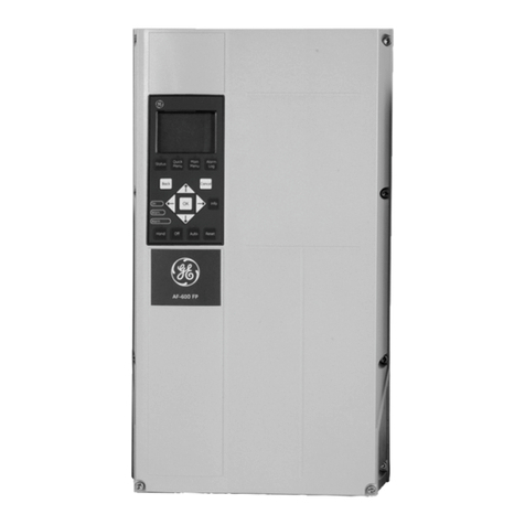
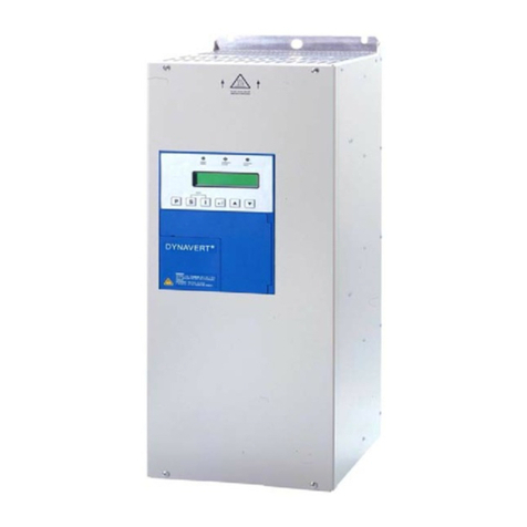
Delt VFD Series Installation guide

2 of 81
Table of Contents
VFD series AC Motor Drives ··························································································3
Motors·················································································································· 10
VFD-E··················································································································15
VFD-L ·················································································································· 42
VFD-EL ················································································································45
C2000/CP2000/CFP2000 ·························································································48
C200···················································································································· 69
MS300 ·················································································································71
ME300 ·················································································································77
VFD-ED················································································································ 78
EMC-PG01O ········································································································· 78
Brake Units ··········································································································· 78
CMM-EIP01··········································································································· 79
AFE Series Active Front End························································································ 80
AFE2000 ··············································································································80

3 of 81
VFD series AC Motor Drives
Q What does the line start lockout function do?
A If Line Start Lockout is disabled, the AC motor drive will run when mains power is
switched on if a RUN command was present at power off.
If Line Start Lockout is enabled, the AC motor drive does not run when mains power
is switched on. It needs a new RUN command after power on.
If between power off and power on the source of operation command is changed, the
AC motor drive can be set to follow this new status or ignore this and keep the old
status.
Q How to dimension brake resistors for VFD?
A Please look for the application note “Dimensioning brake resistors 2008-01.pdf” and
AMD Braking.ppsx on ftp-site (Industrial Automation Products\AMD-Options\AMD
Brake units & resistors\Application notes for braking).
Q Can two drives in parallel control one motor?
A No, with Delta VFD this is not possible.
For this application, drives need to be able to cooperate in master-slave configuration
where one drive acts as master with frequency command input and controls the slave
gate drive.
Q Reset to defaults via Modbus RS-485 communication doesn’t work. Why?
A When a reset to defaults (e.g in VFD-E Pr00-02=9 (Modbus RTU command 01 06
0002 0009) is performed, all parameters, including the communication parameters,
are reset to default.
If the settings you use are different from default (Station address, protocol and/or
Baudrate), they will be reset to the default values and the communication will fail. Also
the source of frequency command and operation command (e.g. Pr02-00 and 02-01
in VFD-E) will be reset to their default values, making it afterwards impossible to
control the drive via Modbus RS-485.
This is an extra attention point that has to be taken into account when setting up serial
communication.

4 of 81
Q Where can I find CAD drawings of the VFD series?
A You can find them on Delta’s download center.
Q How to read/write parameters via serial communication?
Which address to use?
A To read/write parameters in the drives via serial communication, the parameter
number is also the address. However, the address is in Hex format.
Please see examples below:
Pr05-14 = 050Dh
Pr10-03 = 0A03h
Q When and how are the DC-link capacitors to be recharged?
A The drive’s DC link capacitors need to be recharged if the drive has been non-
operational for more than one year. Without recharging, the capacitors may be
damaged when the drive is powered up. The recharging methods are introduced in
the application note Guide For Capacitor Recharging in Delta AC Motor
Drives.pdf which you can download from our ftp-site (Industrial Automation
Products\AMD\General VFD\VFD-General Applications).
Q How to select the potentiometer for the AVI analogue input?
A See the circuit diagram and curves below:
GND
AVI
AVI Input
Resistance
R Ω
Potentio-
meter
aR Ω
+10V
0%
100%
Assume the AVI input resistance is R Ω and the potentiometer value is aR Ω, where
“a” is a ratio.
In the curves diagram the black line represents a fully linear response when the
potentiometer is moved from 0 to 100%.
The green and red curves show the response depending on “a”, the larger “a” is, the
Potentiometer on AVI
0
10
20
30
40
50
60
70
80
90
100
010 20 30 40 50 60 70 80 90 100
Potentiomete r 0-100%
AVI signal 0-100%
a=0.1
a=0.2
a=0.5
a=1
a=2
linear

5 of 81
more non-linear the response becomes, see the red curves.
As an engineering rule of thumb “a” should be ≤0.1 to have an acceptably linear
response, although ≤0.2 is also often accepted.
The next consideration is the current that can be supplied by the 10V terminal. This
gives the minimum allowed potentiometer value. The lower the value is, the more
power is dissipated in the potentiometer, therefore you want to keep the potentiometer
resistance as high as possible.
Example for VFD-E:
- The AVI input resistance is 47kΩ.
- Select potentiometer ≤0.1*47k=4.7k.
- The 10V terminal can supply 3mA so the minimum potentiometer value is
10V/3mA=3.3kΩ.
- So in practice a potentiometer value between 3.3kΩ and 4.7kΩ gives a linear
response and will not overload the 10V terminal (if a≤0.2 is accepted, then a
potentiometer between 3.3kΩ and 10kΩ (=47kΩ/5) can be used).
Q Which parameters must be set when using the built-in brake chopper or a brake
unit?
A The OV stall prevention must be disabled because it would interfere with the brake
chopper action and the DC-bus voltage level at which the brake chopper is activated
must be set.
VFD-EL
VFD-E MS300 ME300 MH300 C2000 C2000
CFP2000
VFD-ED
Disable OV
stall
prevention
Pr06-00=0 Pr06-01=0 n.a.
Set level
n.a. Pr08-19 Pr07-00
Q How to connect a 4-20mA sensor to an analogue input?
A 4-20mA sensors have 2 terminals and “source” the current into the input. They need
normally a minimum voltage drop of ca. 8VDC.
On Delta drives the input impedance of 4-20mA inputs is 250Ω (please refer to the
user manual which input can be used for 4-20mA and how to set it).

6 of 81
At 20mA the input voltage is 5VDC.
So the total supply voltage must be ≥13VDC (5VDC + 8VDC).
The supply voltage must be able to supply at least 20mA.
Internal power supply
In general the 24VDC power supply terminal can be used, except on VFD-L, VFD-M,
VFD-S (A and D version) and VFD-VL.
On VFD-B, VFD-E, VFD-F, VF D -S (E version) and VFD-VE the 24VDC terminal can
supply 20mA, therefore it depends also on the use of the digital inputs whether 20mA
is available.Connection is as follows (also connect DCM to ACM):
+24VDC
ACI 4-20mA
Sensor
4-20mA
DRIVE
20mA max
Voltage drop
>ca. 8VDC
+
-
ACM
DCM
External power supply
For VFD-L, VFD-M, VFD-S and VFD-VL an external power supply must be used of at
least ≥13VDC and ≥20mA. (Delta’s 24VDC power supplies are perfect).
For other drives an external power supply can be used.
The external power supply must be connected as follows:
ACM/GND
ACI 4-20mA
Sensor
4-20mA
DRIVE
20mA max
Voltage drop
>ca. 8VDC
+
-
External power
supply
≥ca. 13VDC
-
+

7 of 81
Q What are the available control modes in the different drives?
A
Series
C2000 CP2000
C200 * B E EL L
V/F OK OK OK OK OK OK OK
V/F+PG OK
OK OK OK
Sensorless
OK OK OK OK OK OK
Vector+PG
OK OK
FOC+PG for IM OK
OK
FOC+PG for PM
OK
TQC+PG for IM OK
OK
TQC+PG for PM
OK
FOC Sensorless
OK
OK
PM Sensorless
OK
OK
TQC Sensorless
OK
OK
Q What is the slip compensation parameter?
A The slip to be compensated in all our drives is calculated as follows:
where
Slip = slip to be compensated
IL= actual load current
INL = no load current
IFL = full load current.
Rated_slip = the motor rated slip in Hz
Slip_compensation = slip compensation factor
In some drives the slip compensation is
The setting range is in that case 0.0~10.0 and the rated slip cannot be entered
separately
In some drives the slip compensation is
The setting range is in that case 0.0~3.0 and the rated slip can be entered separately

8 of 81
Q What is the maximum output frequency with the 599Hz limitation?
A - In VF Mode the maximum output frequency is 599Hz.
- In SVC or Vector Mode the maximum output frequency, including slip compensation,
is 599Hz. Therefore the max frequency command is 599Hz-Slip !
- In FOC mode (C2000) , the max frequency command is limited to (Fset + Pr10-
29)≤599Hz, to make sure the actual output frequency is limited to 599.00Hz.
Q When using a Profibus card how do I change the Baud rate? Do I need to make
any changes in the Menu 9 parameters?
A No, the transmission speed is only set in the master configuration (as shown below)
and the Profibus slave card will auto-detect the speed.
Q What power cable section to use?
A We often get questions about the power cable cross section that is needed in an
application and the relevant info in the user manuals.
In our user manuals, we state the cable cross section that the power terminals can
accommodate. It doesn’t mean you always have to use the indicated cable.
Example: ME300 Frame B

9 of 81
The maximum cable section that these terminals can accommodate is 12AWG or
4mm2.
The minimum cable section that these terminals can accommodate is 18AWG or
0.75mm2.
Because the terminals of a frame size are always the same, it means that the power
terminals of any ME300 in Frame B can accommodate a wire section between
0.75~4mm2.
The actual wire section, that should be used, depends on the application: Current and
Cable length.
• Very long cables or cables for higher current should be thicker
(but in this case not >4mm2).
• Short cables or cable for lower current can be thinner
(but in this case not <0.75mm2).
If you have to or want to use another cable section, please use lugs or ferrules.
The same applies to other frame sizes and Delta drives.

10 of 81
Motors
Q Can a 230V 3-phase motor be driven by a 400V drive?
A Yes, no problem. Just set the Max. Output Voltage Pr01-02=230V.
The output rms voltage is in this case 230V but the peaks are still 560V (from the DC-
bus). But 230V motors in general can handle this.If you use 400V drives, you should
select them based on the motor’s rated current.
Q How to preset speeds and master frequency via Modbus?
A When Frequency command by RS-485 and preset speeds are active, all drives will
accept a change of the master frequency via RS-485 without 04 error, except VFD-E.
Q Why do we measure voltage on PE?
A See diagram:
When PE is left open, both red capacitors (the so-called Y-capacitors) act as a voltage
divider.
The same happens because of capacitors in the built-in filter.
Therefore at PE you will find about half the mains voltage.When PE is connected
(which is very strongly recommended), you will have no problem.
Q Braking with brake resistor doesn’t work well. Why?
A When you use a brake resistor (brake chopper built-in or external brake unit) you have
to disable OV-stall prevention. It will interfere with the braking action, resulting in
longer deceleration rampes than expected.
Please refere to the different user manuals for the exact parameter.

11 of 81
QDo I need to connect the shielding on one end or on both ends?
A -Motor power cables need to be connected on both ends.
-Encoder and control cables need to be connected only at one end.
In both cases, the cable shield needs to have a 360° connection.
Below are some examples of proper shielding connection.
Connecting the shield via a pigtail directly to the VFD ground terminal is not
acceptable.
QWhen using the internal PLC of a VFD, is it possible to use the FPID function
block to control other processes? Or can it only be used for the output
frequency?
A The FPID can only be used to control the output frequency. However, the onboard
PLC does offer two independent PID functions (not in all drives) which can be
assigned to any process. These work by using the Special D registers D1200 to
D1235 as shown below.

12 of 81
In order to enable these PID functions it is necessary to use the Special M contacts
below.
A working example of such a PID function.can be found on our ftp site (Industrial
Automation Products\_Delta Application Guide\General information\Built-in PID
function).
Q How to read/write from/to the onboard PLC through Modbus TCP and Ethernet
IP?
A For the CMC-MOD01 and CMC-EIP01 cards this is supported starting with firmware
V1.08 (date code: W1852).
The drive firmware needs to be at least:
- CP2000 - V2.06 or higher.
- CFP2000 - V1.06 or higher.
- For C2000 this has not yet been released.
For the CMM-MOD01 and CMM-EIP01 cards this is supported starting with firmware
V1.04 (date code: W1850)
The drive firmware needs to be at least:
- MS300 - V1.08 or higher.
You can control the onboard PLC registers and contacts directly through station
address acc. to Pr09-35.

13 of 81
Q In C/CP2000 and MS300: What is the difference between M1042 Quick Stop and
M1044 Pause in the PLC?
A Quick Stop M1042 = 1: Drive will stop with the shortest possible deceleration ramp.
M1042 = 0: Drive start enabled. The drive will not restart by itself.
Pause M1044 = 1: The drive will stop with the normal deceleration ramp.
M1044 = 0: The drive will resume the previous operation with the normal
acceleration ramp. The user does not need to restart.
Q How can I read drive series and model by serial communication?
A Read address 2110hex.
Series Code 2110h High byte 2110h Low byte Type
C2000 20 14h
FFh
Read ID in
Pr00-00
(Address 000h)
CP2000 21 15h
CH2000 22 16h
C200 25 19h
CT2000 30 1Eh
CFP2000 42 2Ah
MH300 31 1Fh
MS300 32 20h
ME300 33 21h
MH300-L 48 30h
C2000HS 49 31h
MH300HS 51 33h
MS300HS 52 34h

14 of 81
Series Code 2110h High byte 2110h Low byte Type
VFD-M 0 00h
ID (as in Pr00-00) N/A
VFD-S 1 01h
VFD-B 2 02h
VFD-L 3 03h
VFD-V/VE 4 04h
VFD-F 5 05h
VFD-E 6 06h
VFD-E-C 7 07h
VFD-EL 8 08h
VFD-VL 9 09h
VFD-DD 13 0Dh
VFD-ED 17 11h

15 of 81
VFD-E
Q How to use the PTC function?
A Please ask for the application note “VFD-E PTC.pdf”. It shows how to set up the VFD-
E for use with PTC acc. to DIN44081/44082 for motor protection.
Q Can an option card be used together with a fieldbus option on the VFD-E?
A Yes, there is room for one option card and one fieldbus option, which can be mounted
together on the VFD-E.
Q What is the function of the dipswitches 1, 2, 3?
A Dipswitch 123
The dipswitches 1,2,3 are meant to be used in case there is no keypad.
If you use keypad, its recommended to set all dipswitches to OFF to avoid
conflict between parameter settings and dipswitches. The dipswitches have priority.
The ex-factory setting of the dipswitches is OFF.
Dipswitch 1 (50Hz defaults)
To set to 50Hz defaults. The following parameters are set: Pr01.00=50Hz and
Pr01.01=50Hz.
Dipswitch 1 = OFF
The defaults are for 60Hz.When keypad is connected it is possible to set Pr00-02=10
(60Hz defaults and all other defaults) or Pr00-02=9 (50Hz defaults and all other
defaults).
Dipswitch 1 = ON
Only Pr01.00=50Hz and Pr01.01=50Hz are set. All other parameters are not
influenced.
When keypad is connected and Pr00-02=10 then display shows "Err" and no
defaults are reset. When keypad is connected and Pr00-02=9 then 50Hz defaults
are set but also all other defaults.

16 of 81
Dipswitch 2 (Free run to stop)
This sets the stop mode. Its identical to setting Pr02 -02=1. It means the stop mode is
free run or coast.
Dipswitch 2 = OFF
When keypad connected Pr02-02 can be set as needed.
Dipswitch 2 = ON
Pr02-02 is set to 1 automatically and when keypad connected other setting results
in "Err" on display.
Dipswitch 3 (ACI)
This sets the frequency command source to ACI.
Dipswitch 3 = OFF
Pr02-00 sets the Frequency command source, see manual.
Dipswitch 3 = ON
The Frequency command source is ACI 4~20mA, independently of the ACI/AVI
dipswitch.
Normally when you set Pr02-00=2 to select ACI/AVI2 and Pr04-19=0 (ACI) or 1 (AVI2),
you can select with the dipswitch ACI/AVI the input to be ACI with 4-20mA or AVI2 with
0-10V.
If input ACI 4-20mA is selected, either via dipswitch 3 or via Pr02.00=2, Pr04-19=0
(default) with dipswitch ACI/AVI=ACI it gives "Aerr" on display and the FAULT LED
lights up because the current is >0mA and <4mA. In case of keypad, the fault "AErr"
can be reset by RESET command (via digital input of keypad depending on Pr02.01)
provided cause of the fault is removed. The FAULT LED can only be reset by power
off/power on, also if the cause of the fault is removed.
In case you want to use AVI2, you need to set Pr04-19=1, then Pr02-00=2, then set
switch ACI/AVI=AVI to avoid "AErr" error.
Therefore, it is recommended to set all dipswitches 1, 2, 3 to OFF in case you use
the keypad.

17 of 81
Q What is the function of the dipswitches ACI/AVI?
A Dipswitch ACI/AVI
Normally when you set Pr02-00=2 to select ACI/AVI2 and Pr04-19=0
(ACI) or 1 (AVI2), you can select with the dipswitch ACI/AVI the input
to be ACI with 4-20mA or AVI2 with 0-10V.
In case you want to use AVI2, you need to set Pr04-19=1, then Pr02-
00=2, then set switch ACI/AVI=AVI to avoid "AErr" error.
The delivery condition is ACI.
QWhat is the function of the dipswitch NPN/PNP?
A It can be used to select the Digital Inputs as NPN (sink) or PNP (source).
Dipswitch NPN/PNP=PNP
The Digital Inputs are PNP (source), see user manual (Sensorless Vecotr Control
Compact Drive VFD-E Series user manual).
Dipswitch NPN/PNP=NPN
The Digital Inputs are NPN (sink), see user manual (Sensorless Vecotr Control
Compact Drive VFD-E Series user manual).
The delivery condition is NPN.
Q Does the option card EME-D33A have PNP inputs?
A Yes, it can be used for PNP inputs. On the card there’s a switch J1 to select PNP or
NPN.
Q Why is Parameter group 11 not visible?
A Parameter group 11 is meant for setting parameters for options. It will become visible
and accessible when an option card is installed and recognized. Please remember to
switch off the power when installing option cards.
Q When I read AVI in a PLC program, why does it not work for frequency command?
A When any digital input/output or any analogue input/output is used in the PLC program,
it loses its normal function.
For example, if Pr02.00=1 (frequency command via AVI) and AVI is read in the PLC

18 of 81
program by reading D1028, then it doesn’t work for frequency command anymore. In
that case, the PLC program needs to include functionality to let the AVI input also
function for frequency command.
Q How to save variables in the PLC at power off?
A The VFD-E PLC cannot save variables when it is power off. However, by writing the
variable to an unused parameter, e.g. the Preset Speeds, it can be done.
Writing Constant K1 to Pr05.14:
Reading Pr05.14 and move to register D20:
Q How to set a 0.01Hz frequency step for the UP/DOWN mode?
A You can set Pr02-07=3, then each time the up/down input is activated, the change is
acc. to Pr02-08, so each step is from 0.01Hz to 10Hz. Since the output frequency
display has only resolution of 0.1Hz, you need 10 steps to notice a change on the
display.
You can set Pr02-07=2. Then the rate of change of the output frequency is acc. to
Pr02-08, so from 0.01Hz/ms to 10.00Hz/ms.
Of course, you need to set Pr02-00=0 for UP/DOWN operation.
Q How to read the PID feedback value via serial communication?
A Set Pr00.04=5 (PID feedback value 0-100%) At address 2116H you can read this
value. In general: At address 2116H you can read the value as selected by Pr00.04.
Q Why does Pr00.04=6 show strange behaviour?
A Pr00.04=6 shows the power factor angle in °(degrees) and not cosphi !

19 of 81
Q How to set a negative slope in AVI-input?
A This is not possible.
The parameters Pr04.00 ~ Pr04.03 can only be used to set Bias and Gain of the front
potentiometer on the keypad. In the examples, however, it is inadvertently suggested
that it also is possible for the AVI-input.
And with Pr04.11 ~ Pr04-14 it is also not possible, because Pr04.12 must be lower
than Pr04.14. (the same applies to the settings of ACI and AVI2).
Q How to set PID?
A To set-up PID do the following:
Pr10-00 to select the PID set point (not via Pr02-00 as e.g. in VFD-B)
Pr10-01 to select the feedback input and positive or negative feedback
[ negative means error=setpoint – feedback ]
[ positive means error=feedback – setpoint ]
Q What is the difference between “AErr” and “FbE” error messages?
A Both messages are generated when the signal on the ACI input is lost. Normally, when
using 4-20mA, if the signal is <4mA.
In normal operation (no PID) with the frequency command via ACI (Pr02-00=2) the
blinking warning “AErr” (Analogue Error) can be displayed when the signal is lost.
In Pr02-06 the required action can be set. The detection cannot be set and is
immediate.
Pr02-06=0. When feedback on ACI is lost, the drive ramps to stop. After
reconnecting ACI the drive goes back to the set frequency.
Pr02-06=1. When feedback on ACI is lost, display shows blinking "AErr" and
coasts to stop. After reconnecting ACI it becomes steady. Press reset, give new
RUN command, and it runs again to the set frequency.
Pr02-06=2. When feedback on ACI is lost, the drive goes to last frequency
command value without any warning on display. After reconnecting ACI the drive
goes back to the set frequency.
When using PID with the feedback signal on ACI, the VFD-E can show the warning
“FbE” (Feedback Error) when the feedback signal is lost. The detection time is set in
Pr10.08. The default value is 60s, so in that case it will take 60s before the warning is

20 of 81
displayed.The required action in case the signal is lost can be set in Pr10-09.
Pr10.09=0. When feedback on ACI is lost, display shows blinking "FbE" and
ramps to stop after 60s, after reconnecting ACI it remains blinking. Press reset,
give new RUN command, and it runs again.
Pr10.09=1. When feedback on ACI is lost, display shows blinking "FbE" and
coasts to stop after 60s, after reconnecting ACI it remains blinking. Press reset,
give new RUN command, and it runs again.
Pr10.09=2. When feedback on ACI is lost, display shows blinking "FbE" after
60s. Because no feedback, the output goes to max frequency, after reconnecting
ACI it goes immediately back to normal PID control.
Q How does the mechanical brake output function in case of faults?
A Normally the brake will be engaged after a STOP command and if the frequency is
lower than the value set in Pr03.12.
After one of the faults OV, OC, LV an internal STOP command is given and because
the motor coasts to 0Hz, the output frequency is immediately 0Hz and lower than
value of P03.12, therefore the brake engages also immediately.
Upon external fault EF, also an internal STOP command is given but because the
drive ramps to 0Hz, the brake will be engaged when the frequency drops below the
value of Pr03.12.
Please set one of the outputs MO1 (Pr03.01) or RA-RC (Pr03.00) to 21 for mechanical
brake control. The frequency values for brake engage and brake release can be set
in Pr03.11 and Pr03.12 respectively.
Q How to clear the status of MI3 when 3-wire operation is selected (Pr04.04=2)?
A When MI3 is on (active) and when Pr04.02=2 to select 3-wire operation, MI3 keeps
its status. To clear this, please power off and power it on again.
This manual suits for next models
9
Table of contents
Popular DC Drive manuals by other brands
Dormakaba
Dormakaba Crane 2000LE Wiring, Setup and Troubleshooting Manual
Leadshine
Leadshine MX3660 Hardware installation manual
Siemens
Siemens SINAMICS V20 Inverter quick guide

GMW
GMW 5201 user manual
Safeway
Safeway CHV-200V-D instruction manual
Assurance Engineering
Assurance Engineering Emergency Lighting Si-36 instruction manual

