manuals.online logo
Brands
  1. Home
  2. •
  3. Brands
  4. •
  5. Toshiba
  6. •
  7. DC Drive
  8. •
  9. Toshiba G7 User guide

Toshiba G7 User guide

Other manuals for G7

5

This manual suits for next models

1

Other Toshiba DC Drive manuals

Toshiba Tosvert VF-A5 User manual

Toshiba

Toshiba Tosvert VF-A5 User manual

Toshiba XM-6401B User manual

Toshiba

Toshiba XM-6401B User manual

Toshiba ACE-tronics G9 ASD User manual

Toshiba

Toshiba ACE-tronics G9 ASD User manual

Toshiba TOSVERT VF-FS1 Series User manual

Toshiba

Toshiba TOSVERT VF-FS1 Series User manual

Toshiba ACE-tronics G9 ASD User manual

Toshiba

Toshiba ACE-tronics G9 ASD User manual

Toshiba APOGEE FLN APG001Z User manual

Toshiba

Toshiba APOGEE FLN APG001Z User manual

Toshiba Q9+ User manual

Toshiba

Toshiba Q9+ User manual

Toshiba T300MVi MEDIUM VOLTAGE User manual

Toshiba

Toshiba T300MVi MEDIUM VOLTAGE User manual

Toshiba PROFIBUS-DP PDP003Z User manual

Toshiba

Toshiba PROFIBUS-DP PDP003Z User manual

Toshiba XM-6201B User manual

Toshiba

Toshiba XM-6201B User manual

Toshiba T300BMV2 User manual

Toshiba

Toshiba T300BMV2 User manual

Toshiba SuperMulti Drive User manual

Toshiba

Toshiba SuperMulti Drive User manual

Toshiba TOSVERT VF-PS1 User manual

Toshiba

Toshiba TOSVERT VF-PS1 User manual

Toshiba G3 Plus Pack Installation and operating instructions

Toshiba

Toshiba G3 Plus Pack Installation and operating instructions

Toshiba T300MV2 User manual

Toshiba

Toshiba T300MV2 User manual

Toshiba CV-10HA User manual

Toshiba

Toshiba CV-10HA User manual

Toshiba G7 User manual

Toshiba

Toshiba G7 User manual

Toshiba Adjustable Speed Drive H7 Series Installation manual

Toshiba

Toshiba Adjustable Speed Drive H7 Series Installation manual

Toshiba TOSVERT VF-P7 User manual

Toshiba

Toshiba TOSVERT VF-P7 User manual

Toshiba GX7R ASD User manual

Toshiba

Toshiba GX7R ASD User manual

Toshiba ATAPI User manual

Toshiba

Toshiba ATAPI User manual

Toshiba S15 User guide

Toshiba

Toshiba S15 User guide

Toshiba TOSVERT VF-P7 User manual

Toshiba

Toshiba TOSVERT VF-P7 User manual

Toshiba CANVIO AEROMOBILE User manual

Toshiba

Toshiba CANVIO AEROMOBILE User manual

Popular DC Drive manuals by other brands

National Instruments NI MID-7604 user guide

National Instruments

National Instruments NI MID-7604 user guide

SOMFY Maestria WT Series instructions

SOMFY

SOMFY Maestria WT Series instructions

Danfoss VLT HVAC Design guide

Danfoss

Danfoss VLT HVAC Design guide

Trane TR150 Service manual

Trane

Trane TR150 Service manual

Chamberlain Garog D Series operating manual

Chamberlain Garog

Chamberlain Garog D Series operating manual

Parker PDS Series user guide

Parker

Parker PDS Series user guide

Binks QS-5012-1-CE Service manual

Binks

Binks QS-5012-1-CE Service manual

Danfoss VLT 2800 Series Quick setup

Danfoss

Danfoss VLT 2800 Series Quick setup

YASKAWA CANopen SI-S3 Technical manual

YASKAWA

YASKAWA CANopen SI-S3 Technical manual

GE D20A6 instructions

GE

GE D20A6 instructions

Danfoss VLT AQUA Drive FC 202 operating manual

Danfoss

Danfoss VLT AQUA Drive FC 202 operating manual

Lenze PositionServo 940 user manual

Lenze

Lenze PositionServo 940 user manual

Unex MC-D-250-1000-050W-TW operating manual

Unex

Unex MC-D-250-1000-050W-TW operating manual

Geckodrive G213V manual

Geckodrive

Geckodrive G213V manual

ABB RSYC-01 user manual

ABB

ABB RSYC-01 user manual

Rockwell Automation PowerFlex 700S Programming manual

Rockwell Automation

Rockwell Automation PowerFlex 700S Programming manual

WEG DeviceNet CFW500 user manual

WEG

WEG DeviceNet CFW500 user manual

Siemens SINAMICS G List manual

Siemens

Siemens SINAMICS G List manual

manuals.online logo
manuals.online logoBrands
  • About & Mission
  • Contact us
  • Privacy Policy
  • Terms and Conditions

Copyright 2025 Manuals.Online. All Rights Reserved.

1
G7/H7 Applications
Workbook
efesotomasyon.com -Toshiba inverter,drive,servo,plc
2
G7 Applications Workbook
©2006 Toshiba International Corporation
Industrial Division
13131 West Little York Road
Houston Texas 77041
Phone 800.231.1412 • Fax 713.896.5242
www.toshiba.com/ind
efesotomasyon.com -Toshiba inverter,drive,servo,plc
TABLE OF CONTENTS
Application Page
Configuring Local / Remote 4
PID Control 9
Three Wire Control 17
Motor Operated Pot (MOP) 19
Configuring Analog Inputs 21
Configuring Analog Outputs 23
Acc/Dec Time Switching Frequency 26
Frequency Priority Switching 28
Trim Pot 30
Customizing Display Units 32
Cyclic Overhauling Loads 34
Sensorless Vector Control (Speed) 35
Sensorless Vector Control (Torque) 39
Feedback Vector Control (Speed) 41
Feedback Vector Control (Torque) 43
Encoder Recommendations 46
G7 Master/Follower Via Communications 48
Master/Follower Using Analog Terminals 53
Basic Drooping 54
Remote Mount EOI 57
Preset Speeds 58
efesotomasyon.com -Toshiba inverter,drive,servo,plc
1
Configuring Local / Remote operations
Introduction
Local/Remote Key – Toggles between the Local and Remote modes. The LED is on when the
system is in the Local mode.
The Local mode allows the Command and Frequency control functions to be carried out via the
EOI.
The Remote mode enables the Command and Frequency control functions to be carried out via the
Control Terminal Strip, LED Keypad, RS232/485, Communication card or Pulse Input.
The availablity of the Local mode of operation may be disabled via Program
⇒
EOI Option Setup
⇒
Local/Remote Key. Here you have the option of selecting Command Mode or Frequency Mode.
The availability of the Local mode of operation may be reinstated by changing this setting, performing
a Reset, or powering down.
EOI
Command Mode Selection Program
⇒
Fundamental Parameters
⇒
Standard Mode Set
Direct Access Number – F003
Parameter Type – Selection List
Factory Default – Use Control Terminal Strip
Changeable During Run – No
The Command Mode selection establishes the source of the command inputs. Command inputs
include Run, Stop, Forward, etc.
*For additional assistance, please contact Toshiba Adjustable Speed Drive Marketing Dept. at (800) 872-2192
4
efesotomasyon.com -Toshiba inverter,drive,servo,plc
*For additional assistance, please contact Toshiba Adjustable Speed Drive Marketing Dept. at (800) 872-2192
5
If the LCD or LED keypad is selected, the Local / Remote key is enabled to select either the
Keypad (local) or the Control Terminal Strip (remote) as the command source.
If the Control Terminal Strip (remote) is selected, it may be programmed to select any of the following
as a source of the command signal:
•Use RR (Factory Default)
•Use LED Keypad (option)
•Use Common (TTL)
•Use RS232/485
•Use Communication Card (option)
Frequency Mode #1 Program
⇒
Fundamental Parameters
⇒
Standard Mode Set
Direct Access Number – F004
Parameter Type – Selection List
Factory Default – Use RR
Changeable During Run – No
The Frequency Mode #1 determines the source of the frequency command or the torque command
(when operating in the torque control mode) of the G7.
If the LCD or LED keypad is selected, the Local / Remote key is enabled to select either the
Keypad (local) or the Control Terminal Strip (remote) as the command source.
Selections are
•Use Vi/II
•Use RR
•Use RX
•Use RX2 (Option Card)
•Use LED Keypad (option)
•Use Binary/BCD Input
•Use LCD Keypad
•Use RS232/485
•Use Communication Card (Option)
•Use MOP Function Simulation
•Use Pulse Input Option
Frequency Mode #2 Program
⇒
Fundamental Parameters
⇒
Standard Mode Set
Direct Access Number – F207
Parameter Type – Selection List
Factory Default – VI/II
Changeable During Run – Yes
efesotomasyon.com -Toshiba inverter,drive,servo,plc
*For additional assistance, please contact Toshiba Adjustable Speed Drive Marketing Dept. at (800) 872-2192
6
This parameter selects the source of the frequency command signal to be used as Frequency Mode
#2 in the event that Frequency Mode#1 is disabled or Frequency Mode #2 is set up as the primary
control parameter.
Selections are
•Use Vi/II
•Use RR
•Use RX
•Use RX2 (Option Card)
•Use LED Keypad (option)
•Use Binary/BCD Input
•Use LCD Keypad
•Use RS232/485
•Use Communication Card (Option)
•Use MOP Function Simulation
•Use Pulse Input Option
Lockout of Local/Remote
Lockout of the Local/Remote can be done by Program
⇒
EOI Setup
⇒
Lockout
⇒
Lockout
Local/Remote.
efesotomasyon.com -Toshiba inverter,drive,servo,plc
*For additional assistance, please contact Toshiba Adjustable Speed Drive Marketing Dept. at (800) 872-2192
7
Operating the G7 with two installed EOIs
Required Equipment
One 120V G7 Demo with simulator terminal strip and two EOIs
Connections
Connect one EOI using the TTL port on the EOI and on the G7
Connect the second EOI using the RS485 port on the EOI and the RS232/485 port on the G7
EOI #2
EOI #1
Programming
EOI Number One (Functionality Start/Stop, Frequency Control, No Programming, No monitoring)
Direct
Access Path Parameter Name Comments
NA EOI Setup Options/Local Remote
Key Command Selection Selected
(default)
NA EOI Setup Options/Local Remote
Key Frequency Selection Selected
(default)
NA EOI Setup Options/Lockout Lockout Reset Selected
NA EOI Setup Options/Lockout Lockout Monitor Selected
NA EOI Setup Options/Lockout Lockout Parameter
Access Selected
NA EOI Setup
Options/Lockout/Password Enable Password Select Enable
Password and
set password to
999
efesotomasyon.com -Toshiba inverter,drive,servo,plc
*For additional assistance, please contact Toshiba Adjustable Speed Drive Marketing Dept. at (800) 872-2192
8
EOI Number Two (Functionality: Run/Stop, No Frequency Control, Full Programming and Monitoring)
Direct
Access Path Parameter Name Comments
NA EOI Setup Options/Local Remote
Key Command Selection Selected
(default)
NA EOI Setup Options/Local Remote
Key Frequency Selection NOT Selected
Instructions
This demonstration makes obvious the ability to use multiple EOIs with one G7 drive. Each EOI may
have different functionality and privileges. This is often desirable when an EOI is mounted at the
drive to facilitate programming, troubleshooting, and monitoring while an additional EOI may be
mounted remotely for use by an operator.
efesotomasyon.com -Toshiba inverter,drive,servo,plc
2
PID Control
Introduction
The built-in PID of the G7 can be used to maintain a constant process variable such as flow,
pressure, temperature, and level. In the example below, the drive is used to vary the speed of the
motor/pump to maintain a constant pressure at the output of the pump. As the valves on the output of
the pump are opened, the pressure goes low. The drive senses this via a 4-20 mA feedback signal
and speeds up to increase pressure up to the desired level. The drive will slow the motor/pump down
as the valves close. The rate at which the drive responds to changes is adjustable via three
parameters (Proportional Gain, Integral Time, and Differential Time) and will have to be field-tuned.
Later in this guideline, PID applications will be discussed in general.
Connections
*For additional assistance, please contact Toshiba Adjustable Speed Drive Marketing Dept. at (800) 872-2192
9
Check your transducer’s schematic for connection information. The above diagram is typical for a loop-powered transducer.
Separately powered isolated transducers feed into the ‘II’ and “CC” terminals. If your transducer is not isolated, order an isolated
input board. The inputs to the standard G7 are not isolated; do not connect the ‘CC’ terminal to ground.
Output Flow
VALVES
//
//
MOTOR
D/A
4
-
20 mA feedback
Transduce
Area in which constant
pressure is desired
II
CC
P24
G7
PUMP
efesotomasyon.com -Toshiba inverter,drive,servo,plc
*For additional assistance, please contact Toshiba Adjustable Speed Drive Marketing Dept. at (800) 872-2192
10
Programming
Direct
Access Parameter Path Parameter Name Comments
F012 ProgramÎFundamental
ParametersÎFrequency Setting Upper Limit Set to 60
F011 ProgramÎFundamental
ParametersÎFrequency Setting Maximum Frequency Set to 60
F009 ProgramÎFundamental
ParametersÎStandard Mode Selection Accel #1 Set to 5
F010 ProgramÎFundamental
ParametersÎStandard Mode Selection Decel #1 Set to 5
F201 ProgramÎFrequency Setting
ParametersÎSpeed Reference
Setpoints
VI/II Set 0 hz at 20%
Set 60 hz at 100%
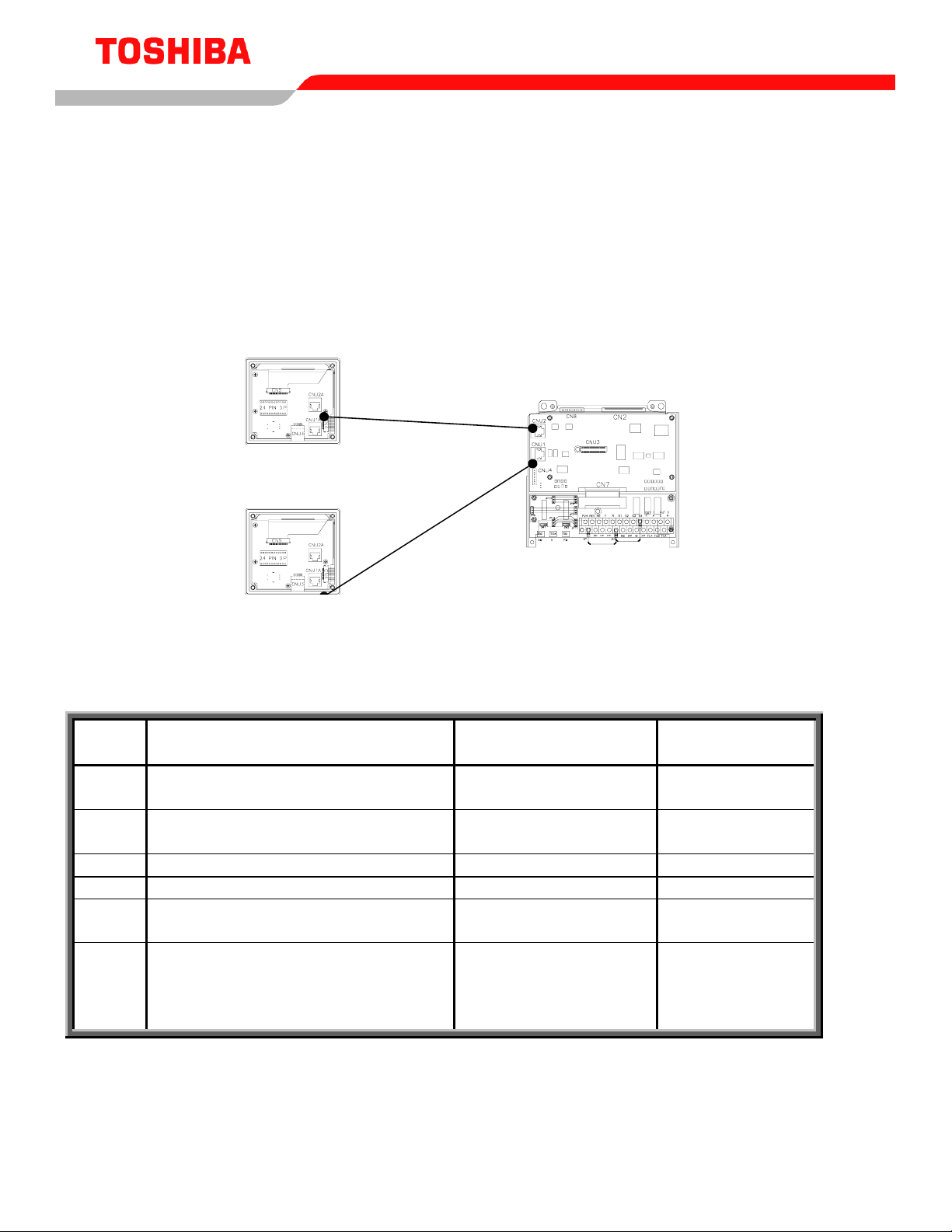
F360 ProgramÎFeedback
ParametersÎFeedback Settings Input Selection Set to VI/II for the PID feedback signal
The above programming assumes a system in which an increase in 4-20 mA feedback signal causes
the drive to reduce output frequency. If the system is such that increasing feedback should cause an
increase in output frequency, the ‘II’ terminal should be reversed by programming the following:
Direct
Access Parameter Path Parameter Name Comments
F201 ProgramÎFrequency Setting
ParametersÎSpeed Reference
Setpoints
VI/II Set 60 hz at 20%
Set 0 hz at 100%
Setting the Setpoint
In general, the setpoint is set by adjusting the setpoint to whatever level (frequency) is necessary to
yield the desired process variable setting. The commanded frequency and actual output frequency
will most likely not be the same; it is only the process variable’s (pressure, temperature, etc.) value
that is of concern. It is the ratio of Frequency Command to Maximum Output Frequency that the drive
uses to determine the feedback value it is trying to maintain (the setpoint).
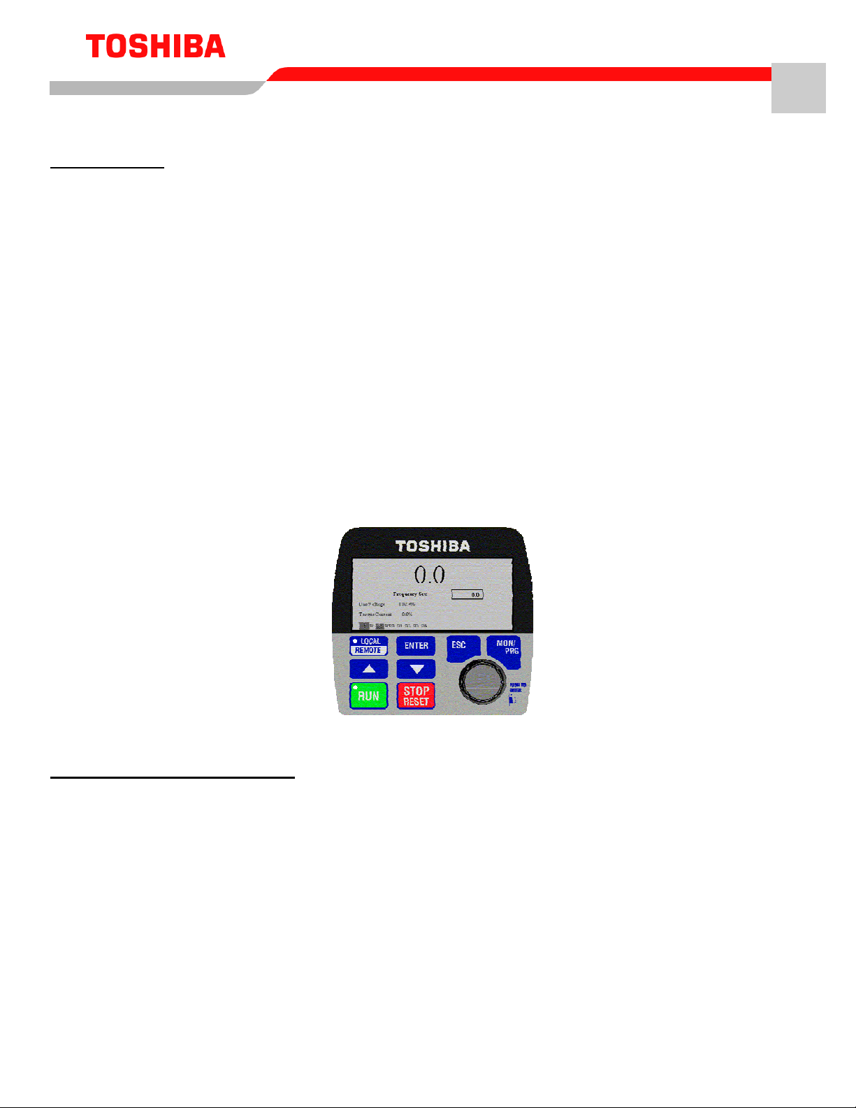
Setpoint via keypad (Local Mode)
Press LOCAL/REMOTE button to illuminate the panel’s green LED. Hit RUN and adjust the keypad
pot to whatever value it takes to develop the desired process variable value. If you still need to setup
the setpoing via the keypad but need to Start/Stop from terminal, then set the F004 Frequency Mode
#1 to Use Common (TTL).
Setpoint via pot on RR terminal (Remote Mode)
Press LOCAL/REMOTE button to turn green LED off. Make F-CC OR R-CC. Adjust RR pot to
whatever setting it takes to generate the desired process variable value.
efesotomasyon.com -Toshiba inverter,drive,servo,plc