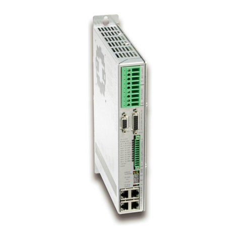
LinMot E1100-GP User manual

Documentation of the Command Table IO interface for the
following Drives:
E1100-G
E1100-G -HC
E1100-G -XC
Command Table IO Interface
User Manual

LinMot
Command Table IO Interface
© 2018 NTI AG
This work is protected by copyright.
Under the copyright laws this publication may not be reproduced or transmitted in any form electronic or mechanical including
photocopying
recording microfilm storing in an information retrieval system not even for didactical use or translating in whole or in
part without the prior written consent of NTI AG.
LinMot® is a registered trademark of NTI AG.
Note
The information in this documentation reflects the stage of development at the time of press and is therefore without obligation.
NTI AG reserves itself the right to make changes at any time and without notice to reflect further technical advance or product
improvement.
Document version 3.14 / June 2 18
Page 2/8 User Manual Command Table IO Interface / 29/ 8/2 18 NTI AG / LinMot

Command Table IO Interface
LinMot
TABLE OF CONTENT
1 SYSTEM OVERVIEW....................................................................................................................4
2 ACTIVATING AND DEACTIVATING OF THE COMMAND TABLE IO INTERFACE......4
3 SMART CONTROL WORD BEHAVIOR.....................................................................................5
3.1 INTF SWITCH ON FLAG BEHAVIOR.....................................................................................................5
3.2 INTF HOME FLAG BEHAVIOR.............................................................................................................5
3.3 INTF ERROR ACKNOWLEDGE FLAG BEHAVIOR......................................................................................5
3.4 INTF GO TO INITIAL POS FLAG BEHAVIOR..........................................................................................5
4 MOTION COMMAND TABLE......................................................................................................6
5 X6 OUTPUT FEEDBACK...............................................................................................................
3.5 OVERRIDE FUNCTIONS FOR OUTPUTS ON X6........................................................................................7
6 CONTACT ADDRESSES................................................................................................................8
NTI AG / LinMot User Manual Command Table IO Interface / 29/ 8/2 18 Page 3/8

LinMot
Command Table IO Interface
1 System Overview
The Command Table IO Interface SW has the following functionality:
Smart Control Word behavior (Enable, Home and Error Acknowledge over one single
IO possible)
Mapping of the X6 inputs to access the motion command table
Mapping of the X6 outputs for system feedback of its state
All this functionality can be wired to the X6 connector that is available on the E11 -GP
drives.
2 Activating and Deactivating of the Command Table IO
Interface
Over the interface switch on the S3.4 the command table IO interface SW can be activated
(switched on) or deactivated (switch off), like all other interface SW on the E11 drive
series.
Page 4/8 User Manual Command Table IO Interface / 29/ 8/2 18 NTI AG / LinMot
I terface
CAN Term
RS485 Term
RS485/232
4
3
2
1
S3
O - Off

Command Table IO Interface
LinMot
3 Smart Control Word Behavior
All control word actions, which are configured in the Command Table IO Interface, affect the
interface control word bits. So if a control word bit is mapped to a X4 IO or is forced by
parameter, this still has priority and the behavior rests unchanged.
3.1 Intf Switch On Flag Behavior
It is strongly recommended to influence the control word bit ‘Switch On‘ over a serial bus
connection or a digital input. For a test system it might be helpful if the system starts up
automatically when switched on. For this case the switch on flag can be set to autostart.
3.2 Intf Home Flag Behavior
Setting the Intf Home Flag Behavior to ‘Autohome’ starts automatically the homing if the state
8 ‘Operation Enabled’ is reached and the status word bit 11 ‘Homed‘ is cleared. When the
homing procedure has finished the interface control word bit 11 ‘Home’ is cleared and the
state 8 is entered again.
3.3 Intf Error Acknowle ge Flag Behavior
Setting the Intf Error Acknowledge Flag Behavior to ‘/Switch On Flag’ sets the interface
control word bit 7 ‘Error Acknowledge’ when releasing the ‘Switch On’ Flag.
3.4 Intf Go To Initial Pos Flag Behavior
Setting the Intf Go to Initial Pos Flag Behavior to ‘Enter Operation Enabled’ sets the interface
Control Word bit 13 ‘Go To Initial Position’ in state ‘Ready to Operate’ (State: 6), normal
operation of this behavior is to move to the ‘Initial position’ after enabling.
NTI AG / LinMot User Manual Command Table IO Interface / 29/ 8/2 18 Page 5/8

LinMot
Command Table IO Interface
4 Motion Command Table
The second and main functionality of the command table IO interface SW is to access the
command table through the X6 inputs. Two different evaluation modes are available:
Coded States ..255 with settling time
Coded States ..255 with Eval on X6.5
In both modes the table below defines the mapping of the inputs to the command table ID
bits.
X6 input pin Command Table ID bit
X6.1 Bit
X6.14 Bit 1
X6.2 Bit 2
X6.15 Bit 3
X6.3 Bit 4
X6.16 Bit 5
X6.4 Bit 6
X6.17 Bit 7
In the first mode with the settling time parameter, the inputs have to be stable for the defined
settling time (UPID: 23 h) until the command is evaluated.
In the second mode the ID inputs are captured on a rising edge of the input X6.5. The input
X6.5 can be filtered (UPID: 23 1h) and inhibited (UPID 23 2h).
Page 6/8 User Manual Command Table IO Interface / 29/ 8/2 18 NTI AG / LinMot

Command Table IO Interface
LinMot
5 X6 Output Feedback
The eight output signals on the X6 connector can be configured for different demands to the
feedback. The table below shows the default configuration of the X6 outputs
X6 output pin UPID Command Table ID bit
X6.9 24 h Op. Main State Bit
X6.22 25 h Op. Main State Bit 1
X6.1 26 h Op. Main State Bit 2
X6.23 27 h Op. Main State Bit 3
X6.11 28 h None
X6.24 29 h Status Word bit ’Motion Active’
X6.12 2A h Status Word bit ’In Target Position’
X6.25 2B h Status Word bit ’Event Handler Active’
With the first four output bits (X6.9, X6.22, X6.1 and X6.22) a direct monitoring of the main
state is possible. Also a transition to the error state can be detected. The output X6.24 is high
if a motion is active, X6.12 is high if no motion is active and the target position is reached
within the configurable limit (UPID 147 h, 147Ch and 1471h). The output X6.25 indicates if
the event handler is active, e.g. during a sequence of motion commands in the motion
command table.
3.5 Overri e Functions for Outputs on X6
For the inputs X6.18 and X6.6 override functions for the X6 outputs can be defined, e.g. if the
input on X6.18 is high the outputs on X6 have not the configured mapping but show the error
code.
The table below shows the default configuration of the override function.
X6 input pin UPID X6 output Override function
X6.18 223 h Show error code
X6.6 224 h None
NTI AG / LinMot User Manual Command Table IO Interface / 29/ 8/2 18 Page 7/8

LinMot
Command Table IO Interface
6 Contact Addresses
-----------------------------------------------------------------------------------------------------------------------------
SWITZERLAND NTI AG
Bodenaeckerstrasse 2
CH-8957 Spreitenbach
Sales and Administration: +41-( )56-419 91 91
Tech. Support: +41-( )56-544 71
Tech. Support (Skype) : skype:support.linmot
Fax: +41-( )56-419 91 92
Web: http://www.linmot.com/
-----------------------------------------------------------------------------------------------------------------------------
USA LinMot USA Inc.
N1922 State Road 12 , Unit 1
Lake Geneva, WI 53147
hone: 262-743-2555
E-Mail: [email protected]
Web: http://www.linmotusa.com/
-----------------------------------------------------------------------------------------------------------------------------
Please visit http://www.linmot.com/ to find the distribution near you.
Smart solutions are…
Page 8/8 User Manual Command Table IO Interface / 29/ 8/2 18 NTI AG / LinMot
Other manuals for E1100-GP
1
This manual suits for next models
2
Table of contents
Other LinMot DC Drive manuals

LinMot
LinMot C1150-SE-XC-0S User manual

LinMot
LinMot C1251-MI-XC-2S-XE User manual

LinMot
LinMot E1100-CO Instruction Manual
LinMot
LinMot E1100 Series User manual
LinMot
LinMot C1250-PD-XC-0S User manual

LinMot
LinMot C1250-EC-XC-0S User manual

LinMot
LinMot E1130-DP-HC User manual

LinMot
LinMot B1100 Series User manual
LinMot
LinMot Step User manual
LinMot
LinMot B1100-PP User manual