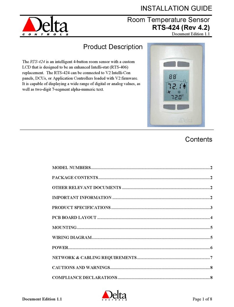
Delta Controls RTS-20 Series User guide

Document Edition 2.3 Page 1 of 13
INSTALLATION & APPLICATION GUIDE
Room Temperature Sensor
RTS-20xxx (Rev 3.0)
Document Edition 2.3
Product Description
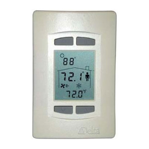
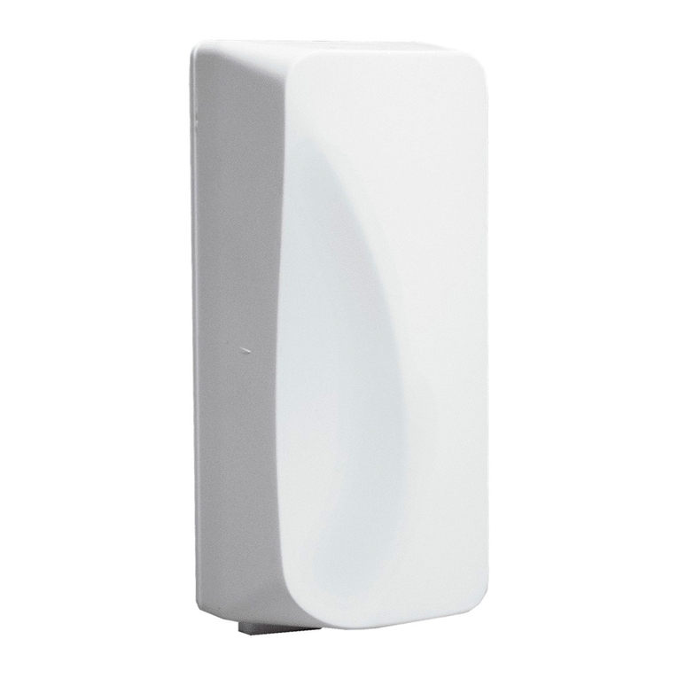
Delta’s Room Temperature Sensors are stylized,
wall mountable devices used to provide remote
room temperature sensing to Delta’s ORCA
system. The RTS-20 comes with a precision
temperature sensor and uses the durable and
attractive plastic housing of Delta’s BACstat II™.
Options for this device include a RJ-11 service
port and an Occupancy Override Push-button and
Setpoint Adjustment Thumb Wheel.
Room Temperature Sensors are ideal for providing
remote temperature sensing, occupancy override
for room schedule control, and remote network
access points.
Contents
MODEL NUMBERS............................................................................................................. 2
PACKAGE CONTENTS ...................................................................................................... 2
OTHER RELEVANT DOCUMENTS................................................................................. 2
PRODUCT SPECIFICATIONS........................................................................................... 3
IMPORTANT INFORMATION.......................................................................................... 4
JUMPERS .............................................................................................................................. 5
WIRING DIAGRAM ............................................................................................................ 6
BOARD LAYOUTS............................................................................................................... 7
MOUNTING .......................................................................................................................... 9
POWER (ONLY RTS-20JXX)............................................................................................. 9
NETWORK & CABLING REQUIREMENTS (ONLY RTS-20JXX).............................9
NETWORK TOPOLOGY (ONLY RTS-20JXX)............................................................. 11
NETWORK COMMUNICATIONS SETUP (ONLY RTS-20JXX)............................... 11
APPLICATION NOTES..................................................................................................... 12
PROGRAMMING (FOR PUSH BUTTON)..................................................................... 12
CAUTIONS AND WARNINGS......................................................................................... 13

Room Temperature Sensor RTS-20xxx (Rev 3.0) Installation & Application Guide
Page 2 of 13 Document Edition 2.3
Model Numbers
Features RTS-
20 RTS-
20J RTS-
20S RTS-
20P RTS-
20PS RTS-
20JPS
Stylized BACstat II Housing 999999
Built-in 10K Thermistor 999999
RJ-11 Service Port 9
9
Occupancy Override Pushbutton 999
20kΩSetpoint Adjust Dial 999
Accessories for the RTS-20Jxx
•TRM-768 Delta Network Terminator for MS/TP
•RPT-768 Delta Network Repeater for MS/TP
Package Contents
•Room Temperature Sensor, RTS-20xxx (Rev 3.0)
•Stylized Enclosure for quick mounting
•RTS-20xxx (Rev 3.0) Installation Guide
Other Relevant Documents
•Delta Controls Wiring Guidelines
•ORCAview Operator Guide
•For Service Tool details see ORCAview Technical Reference Manual (particularly
Appendix H in the V3.30 Manual)

Delta Controls
Document Edition 2.3 Page 3 of 13
Product Specifications
Temperature
•Thermistor: 10,000 ohm @ 77 ºF (25 ºC)
•Accuracy: +/- 0.36 ºF from 32 - 158 ºF (+/- 0.2 ºC from 0 - 70 ºC)
•Stability: 0.24 ºF over 5 years (0.13 ºC)
Connectors
•Screw-type terminal connectors (located on the backplate)
•Optional RJ-11 Service Port jack (6 wire)
Wiring
•2 for optional BACnet MS/TP service port connection (100-120 ohm balanced TSP
cable, 16 PF/FT or lower)
•2 for optional service port power
•2 for temperature
•1 each for optional pushbutton and or setpoint adjustment
Wiring Class
•Class 2
Power
•24 VAC 50/60Hz 3VA (necessary only for the optional service port)
Ambient
•32º to 131º F (0º to 55º C)
•10 to 90% RH (non-condensing)
Size
•4 7/8” x 3 1/4”x 1” (11.4 cm x 7 cm x 2.54 cm)
Weight
•0.16 lb. (71 g.)

Room Temperature Sensor RTS-20xxx (Rev 3.0) Installation & Application Guide
Page 4 of 13 Document Edition 2.3
Important Information
The Room Temperature Sensor RTS-20Jxx Service Port may be installed on a BACnet RS-
485 MS/TP or LINKnet network. Note that this does not make the RTS-20Jxx a MS/TP or
LINKnet device; it simply adds a connection point to the network.
Depending on the model (S, P or SP) There are two inputs available to the controller from
the RTS-20xxx. One first is the push-button that simply shorts the sensing element causing
the temperature to read the highest or lowest value (based on Jumper setting) entered in the
scale range. Programming must be used to interpret this short as a depression of the push-
button and not an actual high or low temperature. See the Programming section for more
details. The second is a 20kΩpotentiometer for Setpoint adjustment that must also be
programmed and set by Jumper as required. See Setpoint Scaling for details.
Setpoint Scaling
(for Setpoint Adjustment)
The setpoint is adjusted using a linear 20kΩ
potentiometer. In a typical 10kΩanalog input, to
get a linear response on the adjustment, use the
examples in the following table or create specific
scales using the equation: Value = Range * Dial
% + Offset
i.e. Value = 4° * 35% - 2° = -0.6°
In the scale table, look up the voltage associated
with 35% (2.31V) for the voltage side and put in
the value calculated into the value side of the
table.
~ Dial % Voltage w/ 10K ± 2° ± 5°
0% (-) 0.00 -2 -5
0% 1.30 -2 -5
5% 1.49 -1.8 -4.5
10% 1.66 -1.6 -4
15% 1.81 -1.4 -3.5
20% 1.95 -1.2 -3
25% 2.08 -1 -2.5
30% 2.20 -0.8 -2
35% 2.31 -0.6 -1.5
40% 2.41 -0.4 -1
45% 2.50 -0.2 -0.5
50% 2.59 0 0
55% 2.67 0.2 0.5
60% 2.75 0.4 1
65% 2.82 0.6 1.5
70% 2.89 0.8 2
75% 2.95 1 2.5
80% 3.01 1.2 3
85% 3.06 1.4 3.5
90% 3.12 1.6 4
95% 3.17 1.8 4.5
100% 3.21 2 5
100% (+) 5.00 2 5

Delta Controls
Document Edition 2.3 Page 5 of 13
Jumpers
THERMISTOR
OVERRIDE
SETPOINT
OVERRIDE CONFIGURATION
The circuit in which the push-button resides is selectable using
the override signal jumper. If the jumper is left in the default
OVERRIDE position, it will short out the separate OVERRIDE
terminal on the thermostat. If the jumper is moved to the
THERMISTOR position, it will short out the thermistor, causing
the read value to be displayed as the highest measurable
temperature. With the jumper is moved to the SETPOINT
position, it will short out the setpoint potentiometer. If moved to
either the THERMISTOR or SETPOINT position, programming
must be used to interpret this short as a depression of the push-
button and not an actual end of scale reading. Note: Do NOT
connect the Override output to the controller unless you have the
jumper in the OVERRIDE position. Doing so may skew the
actual resistance read in the Thermistor or Setpoint inputs.
THERMISTOR
For shorting the reading from the 10kΩthermistor.
OVERRIDE (Default)
For shorting the signal to the OVERRIDE contact.
SETPOINT
For shorting the signal to the 20kΩsetpoint adjust knob.
DIRECT
REVERSE
SETPOINT CONFIGURATION
The circuit in which the setpoint potentiometer resides can be
configured as Direct or Reverse acting. With the jumper set to
Direct, the resistance will get greater as the dial turns
counterclockwise to the warmer designation. Conversely, if the
jumper is set to Reverse, the resistance will decrease as the dial
turns counterclockwise towards the warmer designation.
Internal Circuit Diagram
THERMISTOR
OVERRIDE
SETPOINT
21 21
THERMISTOR
COMMON
SETPOINT
OVERRIDE
DIRECT
REVERSE
100
Ω
20k
Ω
10k
Ω

Room Temperature Sensor RTS-20xxx (Rev 3.0) Installation & Application Guide
Page 6 of 13 Document Edition 2.3
Wiring Diagram
The following wiring diagram displays a controller with 3 separate inputs from the sensor:
Temperature, Setpoint and Override. In this instance the jumper on the RTS-20JPS should
be set to the middle Override position. The controller in this instance has the Temperature
connected to Input 1, the Setpoint connected to Input 2 and the Override signal connected
to Input 3. If the controller requires separate Ground connections for each input, connect
the Common from the RTS-20JPS to each Input ground terminal. The labeling on the
backplate of the RTS-20JPS is labeled: TMP for the 10k Thermistor, SET for the 20k
Setpoint adjust potentiometer and OVR for the Override input.
4-20mA 10k 5V 10V
4-20mA 10k 5V 10V
4-20mA 10k 5V 10V
4-20mA 10k 5V 10V
4-20mA 10k 5V 10V
4-20mA 10k 5V 10V
IP1
GND
IP2
GND
IP3
GND
IP4
GND
IP5
GND
IP6
GND
321
12 PIN
4 5 876 9 10 11 12
CONTROLLER
24~ GND
PWR
+-
NET OVR SET COM TMP
`
24 VAC Power
Connection for optional
Service Port with RTS-
20Jxx
Network Connection
for optional Service
Port with RTS-20Jxx
BACKPLATE
Optional Push-button
and Setpoint
Adjustment Input
Connection
24~ GND +
PWR NET-OVR SET COM TMP
Room Temperture

Delta Controls
Document Edition 2.3 Page 7 of 13
Board Layouts
RTS-20J and RTS-20JPS
Connector Posts for optional
BACnet MS/TP or LINKnet with
RTS-20J and RTS20JPS
Connector Posts for optional 24VAC
with RTS-20J and RTS20JPS
Optional
Push-button with RTS-20JP
Thermistor
Connector Posts for optional
Temperature Sensor
Connector Posts for optional Push
Button Override
Connector Posts for optional Setpoint
Adjustment Thumb Wheel
Thumb Wheel Setpoint Configuration jumper
Override Configuration Jumper
GND ~24[+] [−]TMP COM SET OVR
Assembled on to the
BACstat II top plate

Room Temperature Sensor RTS-20xxx (Rev 3.0) Installation & Application Guide
Page 8 of 13 Document Edition 2.3
RTS-20P, RTS-20S and RTS-20PS
Assembled on to the
BACstat II top plate
RTS-20
Assembled on to the
BACstat II bottom plate
Wiring Terminals

Delta Controls
Document Edition 2.3 Page 9 of 13
Mounting
The back plate is designed for mounting directly on a standard North American, European
or Australian electrical box, but may be mounted in other ways as well. The back plate is
screwed into the dry wall or electrical box and the faceplate snaps into place on top. Use
the hex screw located on the bottom of the housing to secure the faceplate to the back
plate.
Power (Only RTS-20Jxx)
The Room Temperature Sensor with the Service Port option requires a 24 VAC @ 2VA
power supply, typically an isolated Class 2 transformer. More than one device – not
including DCUs or V2 products – may be connected to the same transformer, providing the
transformer is properly sized, including line losses, and polarity is observed between
controllers (in regards to 24~ and GND). The transformer must ONLY be used to provide
power to other MS/TP devices. Auxiliary field devices (i.e., 4-20 mA devices) that don’t
use ½ wave rectification must be powered separately.
Network & Cabling Requirements (Only RTS-20Jxx)
To ensure network stability and reliable communications when using the Service Port
option, particularly at high speeds on a BACnet RS-485 MS/TP network, it is imperative
that you adhere to the following network and cabling requirements:
Item Description
Cabling For BACnet MS/TP networks it is recommended that you use network cabling
that matches the following specifications:
•Balanced 100 to 120 ohm nominal impedance Twisted Shielded Pair
(TSP) Cable
•Nominal capacitance of 16 PF/FT or lower
•Nominal velocity of propagation of 66% or higher
Topology For BACnet MS/TP networks, ensure the cable is installed as a daisy-chain
from one device to the next.
Max. Nodes The maximum number of devices per BACnet MS/TP network without any
repeaters is 50.
Termination
Boards
A termination board must be installed at each end of each BACnet MS/TP
network segment – or two per BACnet MS/TP network. Ensure you do not
overlook this in laying out your network architecture and ordering product.
Repeater A repeater (RPT-768) is not necessary unless more than 50 nodes will be
installed on a network or you need to extend the network beyond 4000 ft (1220
m).

Room Temperature Sensor RTS-20xxx (Rev 3.0) Installation & Application Guide
Page 10 of 13 Document Edition 2.3
For more detailed information, including wiring, refer to the Delta Controls Wiring
Guidelines.

Delta Controls
Document Edition 2.3 Page 11 of 13
Network Topology (Only RTS-20Jxx)
Room Temperature Sensors with a Service Port may be connected to a BACnet RS-485
MS/TP network or to the LINKnet network. Note that this does not make the RTS-20Jxx a
MS/TP or LINKnet device, it simply adds a connection point to the network for use with
the Service Tool.
Network Communications Setup (Only RTS-20Jxx)
The communication speed is set on the network controllers. Refer to the V3.30 ORCAview
Technical Reference Manual for further detail on configuring the MS/TP network or
changing baud rates, etc.
DCU/DSC
(System Device)
BACnet (MS/TP) - Level 3 Network (Subnet)
DAC
(Subnet
Device)
TRM
DAC
(Subnet
Device)
TRM
Level 4
Network
(LINKnet)
16x16 Controller
12x12 Controller
12x8 Controller
6x6 Controller
Room Controller
VAV/VVT Controller
Lighting Controller
BACstat I
BACstat II
(with or without I/O)
Input Field Modules
Subnet Devices
DSC-1616EX [DCU]
DSC-1616(H/E)
DSC-1212(H/E)
DSC-1280(H/E)
DSC-T305
System Devices RS-485
NET1 NET2 NET1 NET2
RS-232
BACstat I
BACstat II
(with No I/O)
BACstat II
(with muxed I/O)
I/O Field Modules
LINKnet Devices
TRM
Level 4
Network
(LINKnet)
DFM
DFM
TRM
LINKnet Notes:
1. Ensure you use the recommended
balanced cable.
2. Ensure the cable is installed as a
daisy-chain from one device to the
next. (1000' or 300m maximum).
3. Ensure you install MS/TP terminator
boards when you have more than 1 or
2 devices.
4. Depending on the controller, up to 12
devices are supported on a LINKnet
network, with limitations on how many
of these may have I/O. (Refer to
the Technical Reference Manual.)
ORCAview
OWS
DFM
Ethernet Note:
If the DCU or DSC has Ethernet capability, it may exist on an
Ethernet network with other controllers in the same building, on which
the ORCAview OWS could reside as well (instead of PTP).
PTP
MS/TP Notes:
1. Ensure you use the recommended balanced cable.
2. Ensure the cable is installed as a daisy-chain from one device to
the next (4,000' or 1220m maximum).
3. Ensure you install an MS/TP terminator board (TRM-768) on each
end of each MS/TP network.
4. The maximum nodes per MS/TP network is 50 without a repeater,
or up to 99 with at least one repeater (RPT-768).
Network Diagram (with V3.22 Firmware)
RTS
RTS RTS
* Note: The RTS is NOT a
network sensor it is connected
to the network to provide
Service Port Access

Room Temperature Sensor RTS-20xxx (Rev 3.0) Installation & Application Guide
Page 12 of 13 Document Edition 2.3
Application Notes
OPERATION
The temperature sensing element and the push-button are on the same circuit. The push-
button simply shorts the sensing element causing the temperature to read the highest
value set in the scale range of the controller. Programming must be used to interpret this
short as a depression of the push-button and not an actual high temperature. See the
Programming section for further details.
PROGRAMMING (for Push button)
The following program is an example of how to read the temperature of the Room
Temperature Sensor without the pushbutton interfering.
Objects (created in the same panel that the RTS is connected to)
AI1 = RTS_20JP**
AV1 = Room_Temp
BV1 = Push_Button
**It is recommended that the Filter value in the AI be set to a lower value (i.e. 20)
so that quick push-button presses are not missed by the controller.
GCL Programming
// Determine if Push-Button has been pressed and ignore open
// circuits
If ((RTS_20JP > 0) OnFor 5S) And (RTS_20JP > Room_Temp + 2) Then
Push_Button = On
End If
If (Push_Button OnFor 5S) Then
Push_Button = Off
End If
// Ensure Push-Button does not interfere with temperature reading
If (Push_Button OffFor 2S) Then
Room_Temp = RTS_20JP
Else
Room_Temp = Room_Temp
End If

Delta Controls
Document Edition 2.3 Page 13 of 13
Cautions and Warnings
WARNING
The RTS Room Temperature Sensor is an Electro-statically sensitive device.
Proper ESD protection (ground strap) should be used when installing this
product so that damage to the product does not occur.
This product conforms to the following UL requirements:
•UL916: Energy Management Equipment.
•CAUTION – Risk of Electric Shock – More than one disconnect
switch may be required to de-energize the equipment before
servicing.
•All terminals are acceptable for Class 2 circuit connection only.
•CAUTION – Input Class 2 Power Supplies are interconnected.
To Reduce the Risk of Fire or Electric Shock, Use only Class 2
sources Suitable for Interconnection.
•Use Copper Conductor Only.
•Select an external power supply that is certified for safety for the
correct destination country and that has an output rating, which
is considered an NEC Class 2 or Limited Power Source with the
rating not to exceed 30 V rms, 42.4 V peak, 100 VA.
•Apply minimum 6.0 lb-in torque for tightening field wires into
the terminal blocks.
This manual suits for next models
5
Table of contents
Other Delta Controls Temperature Controllers manuals
Popular Temperature Controllers manuals by other brands
S+S Regeltechnik
S+S Regeltechnik HYGRASGARD RFF-UP Operating Instructions, Mounting & Installation
ABB
ABB CM 16 manual
Cisco
Cisco Meraki MT10 installation guide
Drayton
Drayton SHR 521 20 Installation & operation manual
Distech
Distech Allure EC-Smart-Vue Series Hardware installation guide

Oregon Scientific
Oregon Scientific THGR511 user manual
