Delta Controls RTS-424 User manual

Document Edition 1.1 Page 1 of 8
INSTALLATION GUIDE
Room Temperature Sensor
RTS-424 (Rev 4.2)
Document Edition 1.1
Product Description
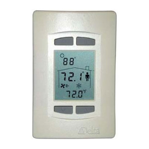
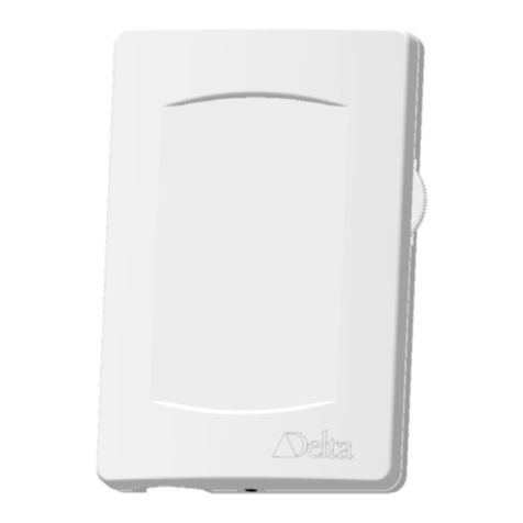
The RTS-424 is an intelligent 4-button room sensor with a custom
LCD that is designed to be an enhanced Intelli-stat (RTS-406)
replacement. The RTS-424 can be connected to V2 Intelli-Con
panels, DCUs, or Application Controllers loaded with V2 firmware.
It is capable of displaying a wide range of digital or analog values, as
well as two-digit 7-segment alpha-numeric text.
Contents
MODEL NUMBERS...............................................................................................................2
PACKAGE CONTENTS........................................................................................................2
OTHER RELEVANT DOCUMENTS ..................................................................................2
IMPORTANT INFORMATION ...........................................................................................2
PRODUCT SPECIFICATIONS ............................................................................................3
PCB BOARD LAYOUT .........................................................................................................4
MOUNTING............................................................................................................................5
WIRING DIAGRAM..............................................................................................................5
POWER....................................................................................................................................6
NETWORK & CABLING REQUIREMENTS ....................................................................7
CAUTIONS AND WARNINGS.............................................................................................8
COMPLIANCE DECLARATIONS ......................................................................................8

Room Temperature Sensor RTS-424 (Rev 4.2) Installation & Application Guide
Page 2 of 8 Document Edition 1.1
Model Numbers
Product Number Product Description
RTS-424 Standard Model (with default button icons and no backlighting)
RTS-424B Standard Model (with default button icons, c/w backlighting)
Button icons:
Bottom 2 buttons are Tand S(Setpoint Adjust), top 2 are Oand I
Package Contents
• RTS-424 Room Temperature Sensor
• RTS-424 Installation Guide
Other Relevant Documents
• RTS-424 Application Guide
• RS-485 Network Installation Guide (DOC818-11)
• Intellicon Zone Controller User Manual ( Overview of Intelli-Stat Sensor and Interface Pg IMX3-2)
Important Information
The RTS-424 does not use the 8 VDC power for Intelli-stats, the RTS-424 requires a 24 VAC or 24 VDC
power supply, which must be different from the power supply used for Intelli-Con or DCU panels.
This device will only communicate over the Intelli-stat network of V2 panels which have an Intelli-stat port.
The following controllers are compatible with RTS-424:
• DCU-050 c/w DXC-053
• ICP-015 Intelli-Con Turbo Panel
• ICP-025 Intelli-Con Mini-Turbo Panel
• ICP-04x Intelli-Con Micro Panel
• IZD-204 Digital Zone Controller
• IZD-206 Digital Zone Controller
• IZA-218 Analog Zone Controller
• IZC-230 VAV/VVT Controller
• IZU-240 Programmable Zone Controller
• Toshiba based Application Controllers loaded with V2 firmware
The RTS-424 is NOT upgradeable to a DNS-24.
The RTS-424 button arrangement for programming is slightly different than the button arrangement of the

Room Temperature Sensor Installation Guide
Product Specifications
Document Edition 1.1 Page 3 of 8
previous Intelli-stat products.
Product Specifications
Power Requirements
• 24 VAC / 24 VDC
• 50 / 60 Hz
• 1.5 VA
• Class II
Ambient Ratings
• 32º to 131º F (0º to 55º C)
• 10 to 90% RH (non-condensing)
Communication Port
ISTAT Connection
• Communications Speed @ 600 bps
• Maximum of 8 devices for programmable control panels
Input (Internal Temperature Sensor)
• Thermistor Input – 10,000 ohm @ 77 ºF (25 ºC)
• Accuracy of +/- 0.36 ºF from 32 - 158 ºF (+/- 0.2 ºC from 0 - 70 ºC)
• Display Resolution of 0.1 ºF or ºC
• Stability of 0.24 ºF over 5 years (0.13 ºC)
Technology
• 8-bit Processor c/w internal A/D, Flash, and RAM
• 2-value LCD with optional backlighting
• 4 stylized momentary push buttons with tactile feedback
Device Addressing
• Set via Keypad Configuration Setup
• Address Range: 1 to 8
Size
• 4 7/8” x 3 1/4”x 1” (11.4 cm x 7 cm x 2.54 cm)
Weight
• 0.27 lb. (122 g.)

Room Temperature Sensor RTS-424 (Rev 4.2) Installation & Application Guide
Page 4 of 8 Document Edition 1.1
PCB Board Layout
AI1 Selection
CPU
Connector Posts
for Power
Connector Posts
for Network
High Voltage Warning
- when devices with
backlighting are on
Service Port
Thermistor (other
side of PCB)
3.268in (83mm)
4.921in(125mm)
NOTE: All field wiring is terminated on the Sensor Backplate mounted on the wall.

Room Temperature Sensor Installation Guide
Mounting
Document Edition 1.1 Page 5 of 8
Mounting
The RTS-424 backplate is designed for mounting directly on a standard North American, European or
Australian electrical box, but may be mounted in other ways as well.
Wiring Diagram
Notes:
1. Follow documented network installation guidelines for Intelli-Stat networks.
2. Do not terminate the network shield on the RTS-424, but ensure shield conductivity is maintained along the
network from end-to-end with wire nuts (i.e., Marrettes™) as necessary.
3. IMPORTANT: Ensure that the network shield and any other bare wires and their connections are all kept in the
wall behind the backplate to ensure that they do not come into contact with the board electronics and cause a
short. Otherwise you run the risk of damaging the RTS-424.
If the same power source is used for more than one RTS-424, ensure that the transformer is properly sized for the
rated VA and ensure that the same polarity is observed from device to device. Each RTS-424 is rated for 1.5 VA
24~ GND
+-
PWR NET
24 VAC/24 VDC
Power Connection
BACKPLATE
Network
Connection

Room Temperature Sensor RTS-424 (Rev 4.2) Installation & Application Guide
Page 6 of 8 Document Edition 1.1
Power
The RTS-424 CAN NOT be powered from the 8 VDC source provided on the I-stat port. The RTS-424
CAN NOT be powered from the same transformer used to power full wave rectified panels.
The following controllers require a separate transformer to power a RTS-424:
• DCU-050 c/w DXC-053
• ICP-015 Intelli-Con Turbo Panel
• ICP-025 Intelli-Con Mini-Turbo Panel
The following controllers may use the 24 VAC out or the same transformer to power the panel as used to
power a RTS-424:
• ICP-04x Intelli-Con Micro Panel
• IZD-204 Digital Zone Controller
• IZD-206 Digital Zone Controller
• IZA-218 Analog Zone Controller
• IZC-230 VAV/VVT Controller
• IZU-240 Programmable Zone Controller
• Toshiba based Application Controllers loaded with V2 firmware
The RTS-424 requires a 24 VAC or 24 VDC @ 1.5 VA power supply, typically an isolated Class II
transformer. Up to 8 RTS-424s may be connected to the same transformer, providing the transformer is
properly sized, including line losses, and polarity is observed between devices (in regards to 24~ and GND).
The transformer must ONLY be used to provide power to other RTS-424 devices. Auxiliary field devices
(i.e., 4-20 mA devices) that do not use ½ wave rectification must be powered separately.
Note: In some existing Intelli-stat installations a power booster is used; be sure to remove this device
before connecting 24 VAC / 24 VDC to the power cable.

Room Temperature Sensor Installation Guide
Network & Cabling Requirements
Document Edition 1.1 Page 7 of 8
Network & Cabling Requirements
To ensure network stability and reliable communications on the Intelli-stat network, adhere to the following network
and cabling requirements:
Item Description
Cabling For RTS-424 networks it is recommended that you use network cabling that matches the
following specifications:
• Balanced 100 to 120 ohm nominal impedance Twisted Shielded Pair (TSP) Cable
• Nominal capacitance of 16 PF/FT or lower
• Nominal velocity of propagation of 66% or higher
*RTS-424 networks have also been tested to a limited degree on unshielded 18 AWG wire with
no ill effects. For new installations it is recommended to use the better cabling mentioned above
as this will help to avoid any potential network communication problems and allow for future
upgrades to V3 MS/TP BACstat networks.
Topology For RTS-424 networks, ensure the cable is installed as a daisy-chain from one device to the
next.
Max. Nodes The maximum number of devices per Intelli-stat network is 8.
For more detailed information, including wiring, refer to the RS-485 Network Installation Guide (DOC818-11).

Room Temperature Sensor RTS-424 (Rev 4.2) Installation & Application Guide
Page 8 of 8 Document Edition 1.1
Cautions and Warnings
WARNING
The RTS-424 is an Electro-statically sensitive device. However, since the electronics are
contained within the housing, and if sufficient care is taken in handling, proper ESD protection
(ground strap) should be unnecessary.
Compliance Declarations
FCC Compliance Information
This equipment has been tested and found to comply with the limits for a Class A digital device, pursuant to
part 15 of the FCC Rules. These limits are designed to provide reasonable protection against harmful
interference when the equipment is operated in a commercial environment. This equipment generates, uses,
and can radiate radio frequency energy and, if not installed and used in accordance with the instruction manual,
may cause harmful interference to radio communications. Operation of this equipment in a residential area is
likely to cause harmful interference in which case the user will be required to correct the interference at his
own expense.
Industry Canada Compliance Statement
ICES-003 This Class B digital apparatus meets all requirements of the Canadian Interference-Causing
Equipment Regulations.
Cet appareil numérique de la Classe B Respecte toutes les exigences du Règlement sur le matérial
brouiller du Canada.
UL Compliance Information
This product conforms to the following UL requirements:
• UL916: Energy Management Equipment
• CAUTION – Risk of Electric Shock – More than one disconnect switch may be
required to de-energize the equipment before servicing
• All terminals are acceptable for Class 2 circuit connection only
• CAUTION – Input Class 2 Power Supplies are interconnected. To Reduce the Risk of
Fire or Electric Shock, Use only Class 2 sources Suitable for Interconnection
• Use Copper Conductor Only
• Select an external power supply that is certified for safety for the correct destination
country and that has an output rating, which is considered an NEC Class 2 or Limited
Power Source with the rating not to exceed 30 V rms, 42.4 V peak, 100 VA.
• Apply minimum 6.0 lb-in torque for tightening field wires into the terminal blocks.
Other manuals for RTS-424
1
Table of contents
Other Delta Controls Temperature Controllers manuals
