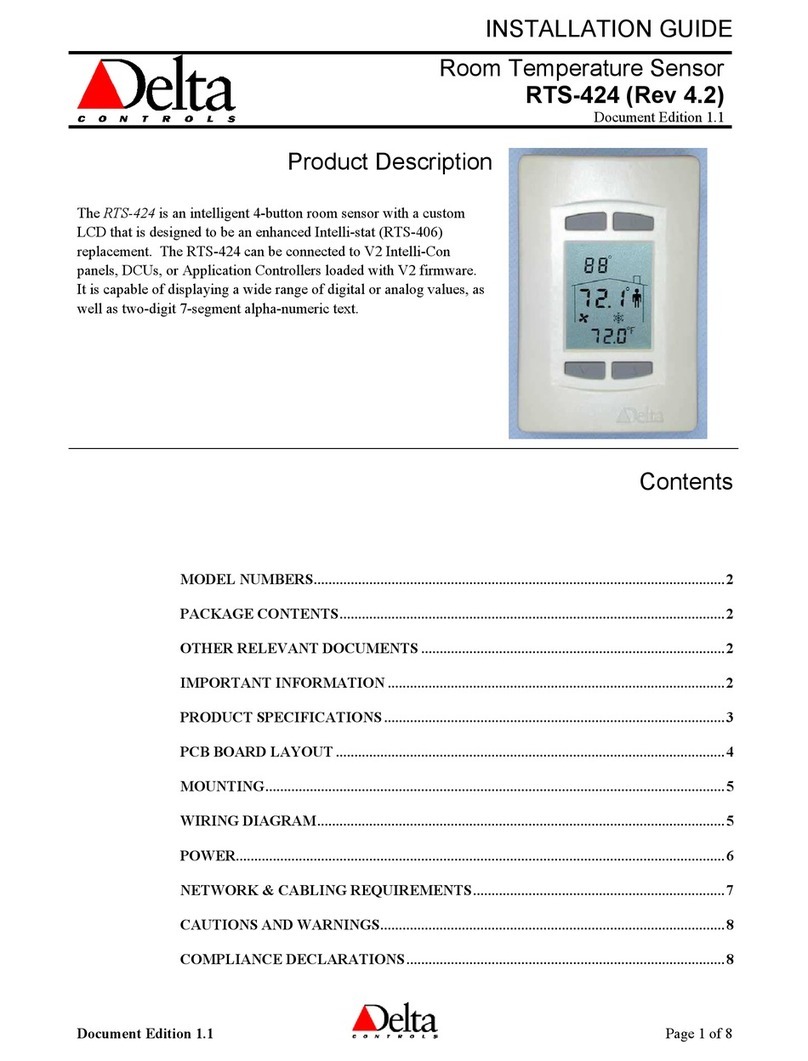
Delta Controls RTS-424 User guide

APPLICATION GUIDE
Room Temperature Sensor:
RTS-424 (Rev 4.2)
Document Edition 1.0
Product Description
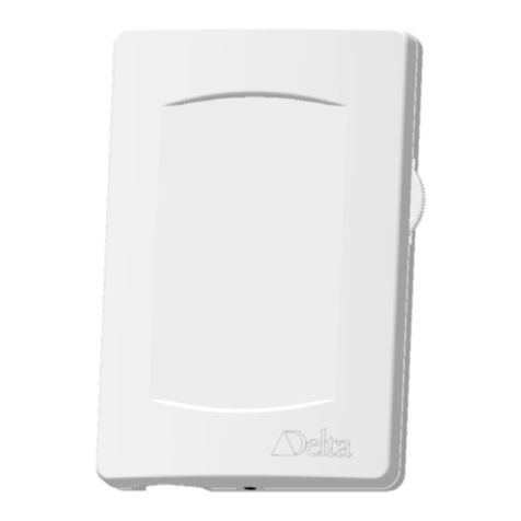
The RTS-424 is an intelligent 4-button room sensor with a custom
LCD that is designed to be an Intelli-stat (RTS-406) replacement.
The RTS-424 can be connected to V2 Intelli-Con panels, DCUs, or
Application Controllers loaded with V2 firmware. It is capable of
displaying a wide range of digital or analog values, as well as three-
digit 7-segment alpha-numeric text.
Contents
MODEL NUMBERS...............................................................................................................3
OTHER RELEVANT DOCUMENTS ..................................................................................3
IMPORTANT INFORMATION! ..........................................................................................3
DEVICE CONFIGURATION (KEYPAD) ...........................................................................4
CHOOSING THE MODE OF OPERATION.......................................................................6
RTS MODE............................................................................................. 6
ENH MODE ............................................................................................ 6
COMMUNICATION ..............................................................................................................7
INITIATING COMMUNICATION................................................................. 7
TROUBLESHOOTING COMMUNICATION................................................... 7
RESTORING COMMUNICATION................................................................ 7
RTS MODE OF OPERATION PROGRAMMING.............................................................8
READING TEMPERATURE ........................................................................ 8
READING BUTTON PRESSES.................................................................... 8
CLEARING BUTTON PRESSES .................................................................. 9
WRITING TO THE RTS-424 DISPLAY ...................................................... 9
ACTIVATING ICONS .............................................................................. 10
USING THE LOCAL SETPOINT FEATURE ................................................ 11
OTHER DISPLAY FUNCTIONS ................................................................ 12
Document Edition 1.0 Page 1 of 26

Room Temperature Sensor Application Guide
Model Numbers
RTS MODE PROGRAMMING EXAMPLE ..................................................................... 15
ENH MODE OF OPERATION PROGRAMMING.......................................................... 19
READING TEMPERATURE ......................................................................19
READING THE LOCAL SETPOINT............................................................20
READING DAY/NIGHT SETPOINTS .........................................................20
CLEARING BUTTON PRESSES.................................................................21
WRITING TO THE RTS-424 DISPLAY AND SETPOINTS ...........................21
ACTIVATING ICONS ...............................................................................22
ENH MODE PROGRAMMING EXAMPLE .................................................................... 24
Page 2 of 26 Document Edition 1.0

Room Temperature Sensor Application Guide
Model Numbers
Model Numbers
Product Number Product Description
RTS-424 Standard Model (with default button icons and no backlighting)
RTS-424B Standard Model (with default button icons, c/w backlighting)
Button icons:
Bottom 2 buttons are Tand S(Setpoint Adjust), top 2 are Oand I
Other Relevant Documents
• RTS-424 Installation Guide
• RS-485 Network Installation Guide (DOC818-11)
• Intellicon Zone Controller User Manual (Overview of Intelli-Stat Sensor and Interface Pg IMX3-2)
Important Information!
1. The following controllers are compatible with RTS-424:
• DCU-050 c/w DXC-053
• ICP-015 Intelli-Con Turbo Panel
• ICP-025 Intelli-Con Mini-Turbo Panel
• ICP-04x Intelli-Con Micro Panel
• IZD-204 Digital Zone Controller (RTS Mode only, no icons)
• IZD-206 Digital Zone Controller (RTS Mode only, no icons)
• IZA-218 Analog Zone Controller (RTS Mode only, no icons)
• IZC-230 VAV/VVT Controller (RTS Mode only, no icons)
• IZU-240 Programmable Zone Controller
• Toshiba based Application Controllers loaded with V2 firmware
2. There are 3 modes of operation for the RTS-424:
• ENH Mode – Highly recommended for new installations. Many icon and setpoint functions are
controlled locally within the RTS rather than at the master panel, so very little programming is
required for highly functional operation.
• RTS Mode – Operates exactly the same as the RTS-406 Intelli-stat but with added icon control
features. This mode of operation is highly recommended for replacement of existing Intelli-stats as it
will not require programming changes in the master panel.
• RTS Mode with local setpoint control – Similar to the RTS-406 but stores the setpoint locally within
the RTS rather than in the master panel.
3. The RTS-424 is NOT upgradeable to a DNS-24.
4. When using a RTS-424 directly connected to the Turbo or Mini-Turbo, make sure that there is no
Intelli-Con Zone Controller or Micro controller addressed as one (1) on the panel zone network. All
communications to the RTS-424s are routed through address one. This address is reserved for Intelli-Stats
and RTS-424s.
5. RTS-424 addresses must be consecutive and must start at one when they are connected to a panel.
6. If communication between the master panel and RTS is interrupted the entire display will start to blink
after 1 minute.
7.
The degree symbol in the center of the displa
y will blink several times after power is applied but before
Document Edition 1.0 Page 3 of 26

Room Temperature Sensor Application Guide
Device Configuration (Keypad)
communication is established. This is similar to the blinking dashed line on the RTS-406.
8. The RTS-424 button arrangement and programming is different than that of previous Intelli-stat products.
9. Local setpoints are automatically retained on power failure.
10. When in RTS Mode the RTS-424 will round the displayed temperature to the nearest whole number such
that the temperature display will only display nn.0. This is a limitation of the original I-stat protocol.
Device Configuration (Keypad)
1. Configuration Menu User Access
Access to the Configuration Menu is protected by an access code or PIN. You must enter the valid PIN before
access is granted; this works as follows:
• First press the Up Arrow (S), and then press the Down Arrow (T) while still pressing the Up Arrow, and
hold them both down for at least 5 seconds.
• When the Pin text is displayed you are being prompted for the valid PIN or access code, a pre-configured
4-digit code, which you must enter before you can gain access to the Configuration Menu. The buttons on the
left side of the BACstat have a value of 0, while the buttons on the right side have a value of 1. Press the
proper button sequence to match the password.
• The PIN is 1011.
• Once you have entered the valid 4-digit code you will gain access to the Configuration Menu, and CFg will
be displayed immediately to indicate you are now in Configuration mode. If you haven’t entered a valid code
(or if you do not press a button within about 10 seconds), the process will be aborted and you will be returned
to normal display mode.
• If at any time after you have gained access to the Configuration Menu you do not press a button for 2 minutes,
the BACstat will exit the Configuration Menu and return to normal display mode.
2. Button & Navigation Functions
The Button functions are as follows within the Configuration Menu:
Button Description
Top Left (O)• Represents a value of 0 when entering the PIN access code.
• PREVIOUS: Enter the current setting (and go backward in the menu).
Top Right (I) • Represents a value of 1 when entering the PIN access code.
• NEXT: Enter the current setting (and go forward to the next item in the menu).
Bottom Left
(Down: T)
• Represents a value of 0 when entering the PIN access code.
• Rotates downward through menu items and options.
• Decreases a numeric value with each button press.
Bottom Right
(Up: S)
• Represents a value of 1 when entering the PIN access code.
• Rotates upward through menu items and options.
• Increases a numeric value with each button press.
Use the NEXT and PREVIOUS buttons to navigate through the menu options. Once you have navigated to the
desired item you wish to display or change, use the arrow buttons to make any necessary changes. Once the
changes are made or you wish to move on, press NEXT or PREVIOUS.
3. Configuration Menu Options
The Configuration Menu is a list of items which you can navigate through and make changes to as you need for
setup purposes. The Configuration Menu items are as follows:
Page 4 of 26 Document Edition 1.0

Room Temperature Sensor Application Guide
Device Configuration (Keypad)
Menu Item Description
CFg Displayed momentarily to indicate you have successfully entered the Configuration
Menu.
tYp Type of Sensor. Options are:
1) RTS – Choosing this option indicates that you would like to configure and
use the RTS-424 in a manner similar to the RTS-406 Intelli-stat. Follow
the RTS Menu selections for the next configuration options.
2) ENH - Choosing this option indicates that you would like to use the RTS-
424 in a manner similar to the Version 3 ENH-24 BACstat II with local
setpoint control. Follow the ENH Menu selections for the next
configuration options.
RTS Menu
DEG The Temperature Units Setting (degrees C or F). Options are:
1) C – Always Display ºC
2) F – Always Display ºF
3) None – Blank out ºand C or F
HSE House Icon. Options are:
1) Yes – Always Display the House Icon
2) No – Always Hide the House Icon
lSp Local Setpoint. Options are:
1) No – Do not store a setpoint in the RTS-424
2) Yes – Store and display a setpoint in the RTS-424
3) Hide – Store but only display a setpoint in the RTS-424 when the up or
down buttons are pushed.
Add The device Address. Options are 1 to 8
End To exit the Configuration Menu (Yes or No). If you do not press a button within 1
minute the device will automatically exit and return to its normal display mode.
ENH Menu
DEG The Temperature Units Setting (degrees C or F). Options are:
1) C – Always Display ºC
2) F – Always Display ºF
3) None – Blank out º and C or F
Set Setpoint - The temperature setpoint for occupied periods.
LO Low - The lowest temperature setpoint that occupants can select during occupied
periods.
HI High - The highest temperature setpoint that occupants can select during occupied
periods.
nHt Night Heat - The temperature setpoint for heating during unoccupied periods.
ncL Night Cool - The temperature setpoint for cooling during unoccupied periods.
DSP Display - The LCD Display Code Setting, a 4-digit value set in the L1, L2, L3 and
dn submenus will configure the local display and button handling as follows:
L1 Line 1 (Top Left – i.e., Outside Value): 1 to 2
1 - Disabled
2 - Value from master panel
L2 Line 2 (Center – i.e., Inside Value): 1 to 2
1 - Disabled
2 - Room Temperature
Document Edition 1.0 Page 5 of 26

Room Temperature Sensor Application Guide
Choosing the Mode of Operation
Menu Item Description
L3 Line 3 (Bottom – i.e., Setpoint Value): 1 to 5
1 - Disabled
2 - No Setpoint until an arrow button is pressed (adjustable)
3 - Setpoint is always displayed (adjustable)
4 - No Setpoint until an arrow button is pressed (not adjustable)
5 - Setpoint is always displayed (not adjustable)
dn House & Day/Night Mode Icons: 1 to 9
HOUSE OUTLINE ON/OFF TEXT MAN SUN/MOON
1 No No No No
2 No Flash No No
3 No Yes No No
4 No No No Yes
5 Yes No No No
6 Yes Yes No No
7 Yes Yes Yes No
8 Yes No Yes No
9 Yes No No Yes
NOTE: Setting the Display Code makes it unnecessary to write GCL programs for
display and button handling.
Ser The Service Tool Mode access setting:
1) 0 - disable access to Service Tool Mode
2) 1 – grant access to Service Tool Mode, enable calibration of temperature
sensor
Add Address - The device Address. Options are 1 to 8
Choosing the Mode of Operation
RTS Mode
RTS Mode operates exactly the same as the RTS-406 Intelli-stat but with added icon control features and a
local setpoint option. Choose this mode of operation if you want to:
• Replace existing Intelli-stats without re-programming the master panel
• Replace existing Intelli-stats and add icon and/or local setpoint features
• Display remote setpoints or other information
• Display text
• Completely control the RTS from the master panel
ENH Mode
ENH Mode is an enhanced mode of operation designed specifically for room control applications. Choose this
mode of operation if you want to:
• Allow local control of room temperature display, room setpoint display, and most icons
• Lessen the amount of GCL required to perform most thermostat operations
Page 6 of 26 Document Edition 1.0

Room Temperature Sensor Application Guide
Communication
Communication
Initiating Communication
Communication to the RTS-424 is set up in exactly the same manner as with the I-stat (RTS-406); the
appropriate Input and Output points must be created to initiate communication. See the RTS Mode of
Operation Programming and ENH Mode of Operation Programming for more information on how to initiate
communication.
Troubleshooting Communication
There are several useful features that make it simple to troubleshoot the status of communication between the
RTS-424 and the master panel:
1. ENH Mode Only - If communication has not been initiated since the last time the thermostat was
reset, the degrees symbol in the center of the display (inside the house) will blink
2. ENH Mode Only - If communication has been initiated since the last time the thermostat was reset,
and it is interrupted, then the entire display will flash on and off.
3. If communication has been initiated since the last time the master panel was reset, and it is
interrupted, then the associated Input.SWITCH field will read 255 (i.e. IPxx.SWITCH = 255).
Note: Do not rely on the status of the temperature displayed in the Input in the master panel for
communication status. If communication is interrupted the Input will continue to display the last value
read from the thermostat.
Communication between the RTS-424 and master panel is not restored automatically if interrupted. The
primary causes of loss of communication are:
1. Power to the RTS-424 is interrupted
2. Intelli-stat network wires are removed or continuity is interrupted
For this reason, ensure that communication is restored every time the thermostat has been placed in the wall
mounting.
Restoring Communication
If communication has been interrupted for some reason then the master panel will cease communicating with
the thermostat. To restore communication simply command the associated Input point in the master panel to
reset (i.e. COMMAND “IPxx RESET”). The following example shows how to achieve this automatically:
IF (IP12.SWITCH = 255) THEN
DO_EVERY 30S
COMMAND “IP12 RESET”
ENDDO
ELSE
. . .
Document Edition 1.0 Page 7 of 26

Room Temperature Sensor Application Guide
RTS Mode of Operation Programming
Reading Temperature
To read temperature and button presses on a RTS-424 addressed as 1, create an analog input with an instance
number set according to the following example:
Type of Control Panel (exp board slot width set to 0) RTS Address Input
DCU-050 c/w DXC-053 1 33
ICP-015 Intelli-Con Turbo Panel 1 25
ICP-025 Intelli-Con Mini-Turbo Panel 1 17
ICP-04x Intelli-Con Micro Panel 1 12
IZU-240 Programmable Zone Controller 1 8
Toshiba based Application Controllers loaded with V2 firmware
with 11 physical inputs or less
1 12
Toshiba based Application Controllers loaded with V2 firmware
with 12 physical inputs
1 13
Toshiba based Application Controllers loaded with V2 firmware
with 16 physical inputs
1 17
Create the next highest input for an RTS-424 addressed as 2 and so on. Assign a 10K thermistor scale range to
the inputs to scale the input to deg C or deg F. If expansion boards are used, create an analog input with an
instance number one higher than possible according to the expansion board slot width set in the CP object.
The temperature input is frequently reset in programming to clear button presses, causing the input value to
drop to zero briefly; it is important to equate the input to a variable with a timing delay so that no interference
occurs. The following programming example shows how to read the temperature and avoid interference
problems:
[WAIT FOR INPUT VALUE TO SETTLE THEN READ TEMPERATURE]
IF (RTS424_TEMP.SWITCH = 0) ON_FOR 5S THEN
ROOM_SPT = RTS424_TEMP
ENDIF
Reading Button Presses
Each button has a value associated with it that can be read by the input using the .SWITCH property. The
.SWITCH values associated with each button are:
Local Setpoint disabled
O= 6, I= 8, T= 4, S= 2
Local Setpoint enabled
O= 6, I= 8, T= 5, S= 5
The following example shows how to read the ON button:
IFONCE (RTS424_TEMP.SWITCH = 8) THEN
Page 8 of 26 Document Edition 1.0

Room Temperature Sensor Application Guide
RTS Mode of Operation Programming
Reading two buttons held down at the same time (local setpoint disabled)
The RTS-424 is capable of reading 2 buttons held down at the same time as a unique number. The coding is
based on the values of each single button:
O= 6, I= 8, T= 4, S= 2
When 2 buttons are pressed at once the numbers are combined as follows:
Buttons Pressed Code
Sand T2.4
Sand O2.6
Sand I2.8
Tand O4.6
Tand I 4.8
O and I6.8
Reading three or more buttons held down at the same time (local setpoint disabled)
A special coding is available when function 1.0 is used to display values. Each button has a value and the code
is made up of the sum of the values of all buttons pressed. The value of each button is:
O= 12.8, I= 3.2, T= 1.6, S= 0.4
When 3 or more buttons are pressed the values are summed together as follows:
Buttons Pressed Code
Sand Tand I5.2
Sand Tand O14.8
Sand Oand I16.4
Tand Oand I17.6
Sand Tand Oand I18
Clearing Button Presses
The value stored in the .SWITCH property of the input will not change until a different button is pressed. In
order to read multiple presses of the same button the .SWITCH value must be cleared after every button press.
This can be done simply by resetting the input. The following is an example of code that should be included in
every program that reads button presses on the RTS-424:
IF (RTS424_TEMP.SWITCH > 0) THEN
RESET RTS424_TEMP
ENDIF
Writing to the RTS-424 Display
To write values to the display on a RTS-424 addressed as 1, create an output with an instance number set
according to the following example:
Document Edition 1.0 Page 9 of 26

Room Temperature Sensor Application Guide
RTS Mode of Operation Programming
Type of Control Panel (exp board slot width set to 0) RTS Address Output
DCU-050 c/w DXC-053 1 33
ICP-015 Intelli-Con Turbo Panel 1 25
ICP-025 Intelli-Con Mini-Turbo Panel 1 17
ICP-04x Intelli-Con Micro Panel 1 12
IZU-240 Programmable Zone Controller 1 8
Toshiba based Application Controllers loaded with V2 firmware
with 11 physical inputs or less
1 12
Toshiba based Application Controllers loaded with V2 firmware
with 12 physical inputs
1 13
Toshiba based Application Controllers loaded with V2 firmware
with 16 physical inputs
1 17
Create the next highest output for an RTS-424 addressed as 2 and so on. If expansion boards are used, create
an analog output with an instance number one higher than possible according to the expansion board slot width
set in the CP object.
The value of the output will be displayed in the center of the RTS-424, provided that the .FUNCTION
property of the output has been set to 0 in GCL.
The following is an example of how to write the value of the input to the center of the display. This program
waits for 4 seconds after the last button is pressed and depends on resetting the input.
[DISPLAY ROOM TEMPERATURE]
IFONCE (RTS424_TEMP.SWITCH = 0) ON_FOR 4S THEN
RTS424_DISPLAY.FUNCTION = 0
RTS424_DISPLAY = ROOM_SPT
ENDIF
Activating Icons
Icons are activated by setting the output .FUNCTION property to 0.4, then writing a value to the RTS-424.
The RTS-424 will interpret the value as a particular icon and display it on the glass. Please refer to the Icon
table below for Icon activation and deactivation codes.
The following is an example of how to activate and deactivate the “Man in the house” icon when the I and O
buttons are pressed:
[OCCUPIED MODE]
IFONCE (RTS424_TEMP.SWITCH = 8) THEN
RTS424_DISPLAY.FUNCTION = 0.4
RTS424_DISPLAY = 108
ENDIF
[UNOCCUPIED MODE]
IFONCE (RTS424_TEMP.SWITCH = 6) THEN
Page 10 of 26 Document Edition 1.0

Room Temperature Sensor Application Guide
RTS Mode of Operation Programming
RTS424_DISPLAY.FUNCTION = 0.4
RTS424_DISPLAY = 8
ENDIF
Icon activation codes using Function 0.4
Icon On Command Off Command Comments
House 101.0 1.0
Humidity 102.0 2.0
Fan 103.N 3.N Use decimal values for fan stages 1,2&3
Values of 0 and 4+ = all stages off
1 = First stage on
2 = First two stages on
3 = all stages on
Heat 104.0 4.0
Cool 105.0 5.0
Sun 106.0 6.0
Moon 107.0 7.0
Man 108.0 8.0
Off 109.0 9.0
On 110.0 10.0
SET 111.0 11.0
TIME 112.0 12.0
CAL 113.0 13.0
MIN 114.0 14.0
MAX 115.0 15.0
AM 116.0 16.0
PM 117.0 17.0
Percent 118.0 18.0
Outdoor degrees 119.0 19.0
Room Degrees 120.0 20.0
Colon 121.0 21.0
Using the Local Setpoint Feature
The RTS-424 has the ability to store a setpoint locally, and display it in the lower portion of the LCD. It also
has the ability to store the setpoint high and low limits locally. To activate this feature please see the
Configuration Menu Options table above.
Reading the Temperature
When the Local Setpoint feature is activated, values other than temperature (i.e. the Local Setpoint) may be passed up
to the master panel. In order to avoid control problems stemming from this type of operation the temperature should
be equated to a variable with a timing delay so that no interference occurs. The following program is an example of
how to read the temperature when the Local Setpoint feature is activated:
[WAIT FOR INPUT VALUE TO SETTLE THEN READ TEMPERATURE]
Document Edition 1.0 Page 11 of 26

Room Temperature Sensor Application Guide
RTS Mode of Operation Programming
IF (RTS424_TEMP.SWITCH = 0) ON_FOR 5S THEN
ROOM_SPT = RTS424_TEMP
ENDIF
Reading the Local Setpoint
The Local Setpoint may be read when the up or down arrows are pressed. When the up or down arrows are
pressed the .SWITCH value of the input will be 5 and the A/D value of the input will represent the value of
the local setpoint. The A/D value of the input must be converted to deg C or deg F by dividing it by 3.2 (3.2 is
used for both deg C and deg F). The following program is an example of how to read the local setpoint:
IF (RTS424_TEMP.SWITCH = 5) THEN
DAY_SP = RTS424_TEMP.AD_VALUE / 3.2
ENDIF
Writing to the Local Setpoint and Setpoint Limits
The Local Setpoint is written to by setting the output .FUNCTION property to 0.4, then writing a value to the
RTS-424. The RTS-424 will interpret the value as a particular local setpoint or setpoint limit. Please refer to
the Local Setpoint table below for Setpoint codes.
Setpoint codes using Function 0.4
Setpoint/Limit Code Comments
Local Setpoint 2nn.n nn.n is the Local Setpoint value
Low Limit 3nn.n nn.n is the Local Low Limit value
High Limit 4nn.n nn.n is the Local High Limit value
Read Local
Setpoint
7nn.n Sending 7nn.n to the stat forces a read
of the Local Setpoint
The following program is an example of how to control the Local Setpoint:
IF (OCCUPIED = ON) THEN
RTS424_DISPLAY = 200 + DAY_SP
ELSE
RTS424_DISPLAY = 200 + NIGHT_SP
ENDIF
Other Display Functions
The RTS-424 is capable of performing all the same functions as the Intelli-stat. Please refer to the table below
for detailed information.
Display Functions
Function Use Comments
0.0 Normal numeric display See above
0.1 Same as 0 Used for reading simultaneous button
presses – see previous Reading Button
Presses section
Page 12 of 26 Document Edition 1.0

Room Temperature Sensor Application Guide
RTS Mode of Operation Programming
0.2 Alpha numeric encoded display See the RTS-424 character table
below
0.3 Reserved
0.4 Icon activation and local setpoints See previous Activating Icons section
0.5 Write to Line 1 of the display Alphanumeric
0.6 Reserved
0.7 Write to Line 1 of the display Signed Numeric
0.8 Reserved
1.0 Same as 0 but enables multiple button
press capability
Used for reading simultaneous button
presses – see previous Reading Button
Presses section
RTS-424 Character Table
The following is a list of the alpha characters associated with various numeric codes and the two digit LED
display when using 0.2 as the output function. The codes for the right digit are 256 times the value of the codes
for the left digit.
Left Digit LCD Codes Right Digit LCD Codes
Char Code Char Code
0 0 0 0
1 0.1 1 25.6
2 0.2 2 51.2
3 0.3 3 76.8
4 0.4 4 102.4
5 0.5 5 128.0
6 0.6 6 153.6
7 0.7 7 179.2
8 0.8 8 204.8
9 0.9 9 230.4
A 1.0 A 256.0
B 1.1 B 281.6
C 1.2 C 307.2
D 1.3 D 332.8
E 1.4 E 358.4
F 1.5 F 384.0
- 1.6 - 409.6
_ 1.7 _ 435.2
blank 1.8 blank 460.8
nv 1.9 nv 486.4
0 2.0 0 512.0
1 2.1 1 537.6
2 2.2 2 563.2
3 2.3 3 588.8
4 2.4 4 614.4
5 2.5 5 640.0
6 2.6 6 665.6
7 2.7 7 691.2
8 2.8 8 716.8
9 2.9 9 742.4
Document Edition 1.0 Page 13 of 26

Room Temperature Sensor Application Guide
RTS Mode of Operation Programming
Left Digit LCD Codes Right Digit LCD Codes
Char Code Char Code
A 3.0 A 768.0
b 3.1 b 793.6
c 3.2 c 819.2
d 3.3 d 844.8
E 3.4 E 870.4
F 3.5 F 896.0
g 3.6 g 912.6
h 3.7 h 947.2
I 3.8 I 972.8
j 3.9 j 998.4
k 4.0* k 1024.0
L 4.1 L 1049.6
m 4.2 m 1074.2
n 4.3 n 1100.8
o 4.4 o 1126.4
P 4.54 P 1152.0
q 4.6 q 1177.6
r 4.7 r 1203.2
S 4.8* S 1228.0*
t 4.9 t 1254.4
u 5.0 u 1280.0
v 5.1* v 1305.6*
w 5.2* w 1331.2*
x 5.3* x 1356.8*
Y 5.4 Y 1382.4
z 5.5* z 1408.0*
decimal (.) 5.6 decimal (.) 1433.6
H 5.7 H H =1459.2
U 5.8 U U =1510.4
*Due to the limitations of a seven segment display, these characters will not look correct.
The code assigned to the appropriate RTS-424 output to display the alpha characters is calculated by adding
the codes for the left and right digits together.
Example: Hi would be 5.7 + 972.8 = 978.5
Note that the output function must be set to 0.2 in GCL prior to assigning the value for display purposes (i.e.,
OP12.FUNCTION = 0.2).
Page 14 of 26 Document Edition 1.0

Room Temperature Sensor Application Guide
RTS Mode Programming Example
The following section is an example of a typical room control program for the RTS-424 when in RTS Mode.
Step 1:
Set the following Menu items to the indicated values:
DEG = C HSE = On LSP = On
RTS Menu
DEG The Temperature Units Setting (degrees C or F). Options are:
1) C – Always Display ºC
2) F – Always Display ºF
3) None – Blank out ºand C or F
HSE House Icon. Options are
1) Yes – Always Display the House Icon
2) No – Always Hide the House Icon
lSp Local Setpoint. Options are:
1) No – Do not store a setpoint in the RTS-424
2) Yes – Store and display a setpoint in the RTS-424
3) Hide – Store but only display a setpoint in the RTS-424 when the up or
down buttons are pushed.
Add The device Address. Options are 1 to 8
End To exit the Configuration Menu (Yes or No). If you do not press a button within 1
minute the device will automatically exit and return to its normal display mode.
Step 2:
Read the sequence of Operation to understand the program application.
Sequence of Operation
Room Temperature
Room Temperature will always be displayed inside the House icon and will be constantly updated when no
other functions are being performed.
Room Temperature Setpoint
The Room Temperature Setpoint will be displayed in the bottom portion of the LCD. The setpoint will be
stored locally and the setpoint variable in the master panel will be updated whenever the local setpoint is
increased or decreased. During occupied periods the Room Temperature Setpoint will be adjustable between
18 and 24 deg C. During unoccupied periods the setpoint will be set to the night heating setpoint of 15 deg C.
Man (Occupancy) Icon
The Man icon will be displayed when the schedule is in an occupied period, or when the occupancy override
button on the stat has been pressed. Occupancy override will last for 1 hour.
Outside Air Temperature
Outside Air Temperature will be displayed at the top of the LCD.
Document Edition 1.0 Page 15 of 26

Room Temperature Sensor Application Guide
RTS Mode Programming Example
Step 3:
Read through the code and create the necessary points in a database. Enter the following code into a program
and test the program. Note that some of the timing may have to be adjusted for your particular application.
[SETPOINTS]
HI_SETPOINT = 24
LO_SETPOINT = 18
NIGHT_SP = 15
[WAIT FOR INPUT VALUE TO SETTLE THEN READ TEMPERATURE]
IF (RTS424_TEMP.SWITCH = 0) ON_FOR 5S THEN
ROOM_SPT = RTS424_TEMP
ENDIF
[SET OCCUPANCY STATUS]
IF (OVERRIDE ON_FOR 1H) OR (SCHEDULE ON) THEN
RESET OVERRIDE
ENDIF
IF (SCHEDULE ON) OR (OVERRIDE ON) THEN
SET OCCUPIED
ELSE
RESET OCCUPIED
ENDIF
[SET OUTSIDE AIR TEMPERATURE UPDATE INTERVAL]
IF (SEND_OAT OFF_FOR 10M) THEN
SET SEND_OAT
ENDIF
IF (SEND_OAT ON_FOR 10S) THEN
RESET SEND_OAT
ENDIF
[SEQUENCE DISPLAY FUNCTIONS]
DO_EVERY 1S
IF (OCCUPIED ON) THEN
SEQUENCE = LIMIT(SEQUENCE + 1 , 0 , 5 )
Page 16 of 26 Document Edition 1.0

Room Temperature Sensor Application Guide
RTS Mode Programming Example
ELSE
SEQUENCE = LIMIT(SEQUENCE - 1 , 0 , 5 )
ENDIF
ENDDO
[READ/WRITE TO RTS-424]
IF (RTS424_TEMP.SWITCH = 0) THEN \ [NO BUTTONS HAVE BEEN PRESSED]
IF (SEQUENCE = 0) OR (SEQUENCE = 5) THEN \ [DISPLAY ROOM TEMP]
IF (SEND_OAT ON) THEN \ [UPDATE OAT VALUE EVERY 10M]
RTS424_DISPLAY.FUNCTION = 0.7
RTS424_DISPLAY = OAT
ELSE
[READ SETPOINT EVERY 10M IN CASE A BUTTON PRESS WAS MISSED]
IF (READ_SETPOINT ON) THEN
RTS424_DISPLAY.FUNCTION = 0.4
RTS424_DISPLAY = 700
IF ((RTS424_DISPLAY = 700) ON_FOR 10S) THEN
DAY_SP = RTS424_TEMP.AD_VALUE / 3.2
ENDIF
ELSE \ [UPDATE ROOM TEMPERATURE]
RTS424_DISPLAY.FUNCTION = 0
RTS424_DISPLAY = ROOM_SPT
ENDIF
ENDIF
ELSE
RTS424_DISPLAY.FUNCTION = 0.4
IF (SEQUENCE = 1) THEN \ [CONTROL MAN ICON]
IF (OCCUPIED ON) THEN
RTS424_DISPLAY = 108
ELSE
RTS424_DISPLAY = 8
ENDIF
ELSE
IF (SEQUENCE = 2) THEN \ [SET HIGH SETPOINT ADJUST LIMIT]
IF (OCCUPIED ON) THEN
RTS424_DISPLAY = 400 + HI_SETPOINT
ELSE
RTS424_DISPLAY = 400 + NIGHT_SP
Document Edition 1.0 Page 17 of 26

Room Temperature Sensor Application Guide
RTS Mode Programming Example
ENDIF
ELSE
IF (SEQUENCE = 3) THEN \ [SET DAY/NIGHT SETPOINT]
IF (OCCUPIED = ON) THEN
RTS424_DISPLAY = 200 + DAY_SP
ELSE
RTS424_DISPLAY = 200 + NIGHT_SP
ENDIF
ELSE
IF (SEQUENCE = 4) THEN \ [SET LOW SETPOINT ADJUST LIMIT]
IF OCCUPIED = ON THEN
RTS424_DISPLAY = 300 + LO_SETPOINT
ELSE
RTS424_DISPLAY = 300 + NIGHT_SP
ENDIF
ENDIF
ENDIF
ENDIF
ENDIF
ENDIF
ELSE \ [A BUTTON HAS JUST BEEN PRESSED]
[READ LOCAL SETPOINT VALUE]
IF (RTS424_TEMP.SWITCH = 5) AND (OCCUPIED ON) THEN
DAY_SP = RTS424_TEMP.AD_VALUE / 3.2
ENDIF
[READ OCCUPANCY OVERRIDE BUTTON]
IF (RTS424_TEMP.SWITCH = 8) THEN
SET OVERRIDE
ENDIF
[CLEAR BUTTON PRESSES]
RESET RTS424_TEMP
ENDIF
[END OF PROGRAM]
Page 18 of 26 Document Edition 1.0

Room Temperature Sensor Application Guide
ENH Mode of Operation Programming
Reading Temperature
To read temperature and button presses on a RTS-424 addressed as 1, create an analog input with an instance
number set according to the following example:
Type of Control Panel (exp board slot width set to 0) RTS Address Input
DCU-050 c/w DXC-053 1 33
ICP-015 Intelli-Con Turbo Panel 1 25
ICP-025 Intelli-Con Mini-Turbo Panel 1 17
ICP-04x Intelli-Con Micro Panel 1 12
IZU-240 Programmable Zone Controller 1 8
Toshiba based Application Controllers loaded with V2 firmware
with 11 physical inputs or less
1 12
Toshiba based Application Controllers loaded with V2 firmware
with 12 physical inputs
1 13
Toshiba based Application Controllers loaded with V2 firmware
with 16 physical inputs
1 17
Create the next highest input for an RTS-424 addressed as 2 and so on. If expansion boards are used, create an
analog input with an instance number one higher than possible according to the expansion board slot width set
in the CP object.
Set the value of the filter in the input to 0 (the input is internally filtered). The following degrees C or F
scale range must be entered for accurate temperature measurement:
Voltage Temperature ( °C ) Temperature ( °F )
0.00 7.0 45.0
0.31 8.8 48.1
0.63 10.5 51.3
0.94 12.3 54.4
1.25 14.0 57.5
1.56 15.8 60.6
1.88 17.5 63.8
2.19 19.3 66.9
2.50 21.0 70.0
2.81 22.8 73.1
3.13 24.5 76.3
3.44 26.3 79.4
3.75 28.0 82.5
4.06 29.8 85.6
4.38 31.5 88.8
4.69 33.3 91.9
5.00 35.0 95.0
Document Edition 1.0 Page 19 of 26

Room Temperature Sensor Application Guide
ENH Mode of Operation Programming
Note: there is a slight mismatch between the value displayed on the RTS and the value displayed in ORCAview.
This can be partially corrected for using by using the calibration field of the IP.
In ENH Mode values other than the temperature (i.e. the Local Setpoint) may be passed up to the master panel. In
order to avoid control problems stemming from this type of operation the temperature should be equated to a variable
with a timing delay so that no interference occurs. The following program is an example of how to read the
temperature when the Local Setpoint feature is activated:
[WAIT FOR INPUT VALUE TO SETTLE THEN READ TEMPERATURE]
IF (RTS424_TEMP.SWITCH = 0) ON_FOR 5S THEN
ROOM_SPT = RTS424_TEMP
ENDIF
Reading the Local Setpoint
The .SWITCH values associated with up and down buttons are:
T= 5, S= 5
The Local Setpoint may be read when the up or down arrows are pressed. When the up or down arrows are
pressed the .SWITCH value of the input will be 5 and the value of the input will be the value of the local
setpoint. The following program is an example of how to read the local setpoint:
IF (RTS424_TEMP.SWITCH = 5) THEN
DAY_SP = RTS424_TEMP
ENDIF
The local setpoint can also be commanded to be passed up to the master panel by changing the output function to 0.4
(OPxx.FUNCTION = 0.4) and sending the command OPxx = 700.
Reading Day/Night Setpoints
The .SWITCH values associated with up and down buttons are:
O = 6, I = 8
The Local Day and Night Setpoints may be read when the occupied or unoccupied buttons are pressed. When
the occupied button is pressed the .SWITCH value will be 6 and the value of the input will be the value of Day
Setpoint. When the unoccupied button is pressed the .SWITCH value will be 8 and the value of the input will be
the value of Night Setpoint. The following program is an example of how to read the Local Day and Night
Setpoints:
[READ DAY SETPOINT]
IF (RTS424_TEMP.SWITCH = 6) THEN
DAY_SP = RTS424_TEMP
ENDIF
[READ NIGHT SETPOINT]
IF (RTS424_TEMP.SWITCH = 8) THEN
NIGHT_SP = RTS424_TEMP
ENDIF
Page 20 of 26 Document Edition 1.0
Other manuals for RTS-424
1
Table of contents
Other Delta Controls Temperature Controllers manuals
Popular Temperature Controllers manuals by other brands

sauter
sauter EGH130F931 operating instructions

Temperature Guard
Temperature Guard VM500-2 Operating Manual and Installation Instructions

AKO
AKO AKO-16525AN user manual

RKC INSTRUMENT
RKC INSTRUMENT REX-P48 Series Operation manual

Penn
Penn A421ABT series installation instructions

Viessmann
Viessmann VITOSOLIC 200 operating instructions