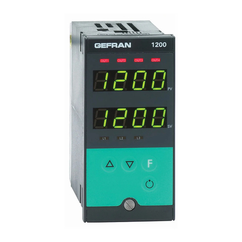
gefran 850 Quick guide

Double PID temperature controller
850 - 1650 - 1850
code: 80209C - 01-2020
80209C_MHW_850-1650-1850_02-2020_ENG
INSTALLATION AND
INSTRUCTION MANUAL


80209C_MHW_850-1650-1850_20-2020_ENG_pag. 1
CONTENTS
CONTENTS................................................................ 1
Introduction............................................................... 7
Device data ......................................................................................7
Warnings and safety.........................................................................7
Typographical conventions used in this manual ..............................8
Glossary ...........................................................................................8
Disclaimer.........................................................................................9
Copyright..........................................................................................9
1. GENERAL DESCRIPTION ..............................10
1.1. Profile ...................................................................................10
1.2. Differences among models ..................................................11
1.3. 850 Controller.......................................................................12
1.3.1. Display and keys........................................................12
1.3.2. Drilling dimensions and templates.............................14
1.4. 1650 Controller.....................................................................15
1.4.1. Display and keys........................................................16
1.4.2. Drilling dimensions and templates.............................17
1.5. 1850 Controller.....................................................................18
1.5.1. Display and keys........................................................19
1.5.2. Drilling dimensions and templates.............................20
2. INSTALLATION................................................21
2.1. Mounting the controller........................................................21
2.1.1. General installation rules............................................21
2.1.2. Drilling dimensions.....................................................21
2.1.3. Protection against infiltration of dust ......................and
water ..........................................................................21
2.1.4. Vibrations ...................................................................22
2.1.5. Minimum space for ventilation...................................22
2.1.6. Positioning .................................................................22
2.1.7. Fastening to the panel ...............................................22
2.2. Connections .........................................................................23
2.2.1. General rules for connections....................................23
2.2.2. Electromagnetic compatibility (EMC).........................23
2.2.3. Cables........................................................................23
2.2.4. Power supply .............................................................23
2.2.5. Connecting inputs and outputs .................................24
2.3. 850 connection diagrams.....................................................25
2.3.1. General diagram.........................................................25
2.3.2. Power supply .............................................................26
2.3.3. Inputs .........................................................................26
2.3.4. Outputs ......................................................................26
2.3.5. Digital inputs ..............................................................27
2.3.6. Serial line....................................................................28
2.3.7. CT inputs....................................................................28
2.3.8. Auxiliary inputs...........................................................28
2.3.9. Auxiliary outputs ........................................................28
2.4. 1650 connection diagrams...................................................29
2.4.1. General diagram.........................................................29
2.4.2. Power supply .............................................................30
2.4.3. Inputs .........................................................................30
2.4.4. Outputs ......................................................................30
2.4.5. Digital inputs ..............................................................31
2.4.6. Serial line....................................................................31
2.4.7. CT Inputs ...................................................................31
2.4.8. Auxiliary inputs...........................................................32
2.4.9. Analog outputs...........................................................33
2.5. 1850 connection diagrams...................................................34
2.5.1. General diagram.........................................................34
2.5.2. Power supply .............................................................36
2.5.3. Inputs .........................................................................36
2.5.4. Outputs ......................................................................36
2.5.5. Digital inputs ..............................................................37
2.5.6. Serial line....................................................................38
2.5.7. CT Inputs ...................................................................38
2.5.8. Auxiliary input.............................................................38
2.5.9. Third Analogue Input (Aux2).......................................39
2.5.10. Analog outputs...........................................................39
2.5.11. Connections with option I / O (N) ..................................
with optional (N) =10, 01,11.......................................39
2.6. RS485 serial connection diagram ........................................40
2.7 Ethernet port wiring diagram................................................42
3. COMMISSIONING...........................................43
3.1. Information on displays and use of keys..............................43
3.1.1. Navigating the menus ................................................43
3.1.2. Displays......................................................................43
3.1.2.1. Display characters .............................................43
3.1.2.2. Scrolling messages ...........................................44
3.2. Sequence at power-on.........................................................44
3.3. First power-on ......................................................................45
3.3.1. Fast configuration ......................................................45
3.4. Setting up quick configuration .............................................49
3.4.1. Setting up the Alarm ..................................................49
3.4.2. Setting up the Heater Break Alarm ............................50
3.4.3. Setting up the PID......................................................51
4. CONFIGURATION ...........................................52
4.1. Programming/Configuration Menu.......................................52
4.1.1. First: know what you’re doing....................................52
4.1.2. Passwords .................................................................52
4.1.3. Password in the User Menu.......................................52
4.2. Main menu ...........................................................................53
4.2.1. Functional schema.....................................................55
4.3. Legend for submenus and parameters................................56
4.3.1. Submenu....................................................................56
4.3.2. Parameter ..................................................................56
4.4. Submenu INFO - information display...................................57
4.4.1. SW.VER - Software version........................................58
4.4.2. CODE - Identifying code of controller.......................58
4.4.3. ERR.1 - Main input error ............................................58
4.4.4. ERR.2 - Auxiliary input error.......................................58
4.4.5. ERR.3 - Auxiliary input error 2 (IN3) ..........................59
4.4.6. M.ERR.x* - Math function block x* error....................59
4.4.7. SAP.C - SAP Code .....................................................59
4.4.8. SER.N - Serial number of controller...........................59
4.4.9. xxxxx - Model of controller ........................................60
4.4.10. xxxxx - Type of controller...........................................60
4.4.11. FUNC.B - Logic and Math functions option available.... 60
4.4.12. CALEN - Calendar Available ......................................60
4.4.13. IN.AUX - Auxiliary input available ..............................60
4.4.14. I.AUX2 - Auxiliary input 2 available ............................61
4.4.15. OUT.AN - Analog output available .............................61
4.4.16. CTx - Current transformer input available..................61
4.4.17. x.IN.DG - Digital input available .................................61
4.4.18. RS485 - RS485 serial port available ..........................61
4.4.19. MAC.E - Controller Ethernet Address........................62
4.4.20. IO.AUX – Auxiliary digital I/Os available.....................62
4.4.21. IO.RELE – Auxiliary relays available...........................62
4.4.22. PS.MAI – Sensor power supply available for main
input ...........................................................................62
4.4.23. PS.AUX – Sensor power supply available for auxiliary
input ...........................................................................62
4.4.24. OUT1 - Type of output 1 ............................................63
4.4.25. OUT2 - Type of output 2 ............................................63
4.4.26. OUT3 - Type of output 3 ............................................63
4.4.27. OUT4 - Type of output 4 ............................................63
4.4.28. OUT1.S - Number of switchings output 1 .................63
4.4.29. OUT2.S - Number of switchings output 2 ................64
4.4.30. OUT3.S - Number of switchings output 3 ................64
4.4.31. OUT4.S - Number of switchings output 4 ................64
4.4.32. INDG.S - Digital input switchings number ................64
4.4.33. T.DAYS - Total working days......................................64

80209C_MHW_850-1650-1850_20-2020_ENG_pag. 2
4.4.34. P.DAYS - Partial working days ...................................65
4.4.35. T.INT - Internal temperature of controller...................65
4.4.36. T.MIN - Minimum internal temperature of the controller ......65
4.4.37. T.MAX - Maximum internal temperature of the controller ....65
4.4.38. TIME - Internal time....................................................65
4.4.39. DATE - Internal date..................................................65
4.5. INFO.E Submenu - Displaying Ethernet Information ...........66
4.5.1. VERS.E – Ethernet Software Version .........................67
4.5.2. TY.S.E – Ethernet assignment mode status ...........................67
4.5.3. CON.E – Ethernet Connection status ........................67
4.5.4. LIN.E – Ethernet link status........................................67
4.5.5. SPD.E – Ethernet speed status..................................67
4.5.6. IP.E – Ethernet IP Address .........................................68
4.5.7. SUB.E – Subnet mask Ethernet .................................68
4.5.8. GAT.E – Ethernet Gateway address ...........................68
4.5.9. STA.E – Ethernet Network status...............................68
4.6. MASTER Submenu - Display of Master Modbus
communication information and values ...............................71
4.6.1. STAT – Master communication status........................71
4.6.2. MAS.xx – Master communication value xx............................71
4.7. Submenu PR.OPT - Configuring programs.............................72
4.7.1. RECP.N - Selecting a recipe ......................................71
4.7.2. FI.STP - Number of first step assigned to program........73
4.8. Submenu PR.STP - Configuration of program steps..............75
4.8.1. PR.NUM ..........................................................................76
4.8.2. PR.ST.N - Programming step..........................................76
4.8.3. ST.END - End step of the program configuration............76
4.8.4. REFE – Step reference programmer ...............................76
4.8.5. SETP - Programming step setpoint ................................76
4.8.6. RAMP.T - Step time ramp................................................77
4.8.7. HOLD.T - Hold time in step.............................................77
4.8.8. HBB - Enable Hold Back Band function .........................77
4.8.9. BAND - Maximum deviation for HBB..............................77
4.8.10. HBB.R - Enabling HBB during ramp .............................78
4.8.11. HBB.H - Enabling HBB during hold ..............................78
4.8.12. HBB2 - Enabling HBB with respect to the auxiliary input....78
4.8.13.
S.SP.EN - Enabling retransmission of setpoint to analog
output .........................................................................
78
4.8.14. SUB.SP - Setpoint value of slaved controller ..............79
4.8.15. S.RM.EN - Enabling ramp for slaved controller ............79
4.8.16. ENBL.1 - Consent 1 to execute step ............................79
4.8.17. ENBL.2 - Consent 2 to execute step ............................79
4.8.18. ENBL.3 - Consent 3 to execute step ............................80
4.8.19. ENBL.4 - Consent 4 to execute step ............................80
4.8.20. EN.ST.N - Other programmer step as consent to execute
step ...............................................................................80
4.8.21. EVN.R.1 - Event 1 during step ramp .............................80
4.8.22. EVN.R.2 - Evento 2 durante la rampa del passo...........81
4.8.23. EVN.R.3 - Event 3 during step ramp .............................81
4.8.24. EVN.R.4 - Event 4 during step ramp .............................81
4.8.25. EVN.H.1 - Event 1 during step hold ..............................81
4.8.26. EVN.H.2 - Event 2 during step hold ..............................82
4.8.27. EVN.H.3 - Event 3 during step hold ..............................82
4.8.28. EVN.H.4 - Event 4 during step hold ..............................82
4.8.29. GROP.R - Group of parameters assigned to ramp........82
4.8.30. GROP.H - Group of parameters assigned to hold.........83
4.8.31. MSG.R - Message associated with the ramp ...............83
4.8.32. MSG.H - Message associated with the maintenance........ 83
4.9. Submenu INPUT - Configuring analog inputs.........................84
4.9.1. Functional schema ..........................................................85
4.9.2. INP.N - Selecting the analog input ..................................85
4.9.3. TYPE - Selecting sensor type .........................................86
4.9.4. SBR.E - Enabling SBR error............................................89
4.9.5. LIN - Selecting linearization type ...................................91
4.9.6. UNIT - Selecting the displayed unit of measurement .....91
4.9.7. FILT - Digital filter ............................................................91
4.9.8. FILT.D - Digital filter on PV display ..................................92
4.9.9. DEC.P - Number of decimals displayed .........................92
4.9.10. LO.SCL - Lower limit of scale .......................................93
4.9.11. HI.SCL - Upper limit of scale ........................................93
4.9.12. OF.SCL - Scale offset correction...................................94
4.9.13. LO.SP - Lower limit for setpoint....................................94
4.9.14. HI.SP - Upper limit for setpoint.....................................94
4.9.15. LO.AL - Lower limit for alarms ......................................94
4.9.16. HI.AL - Upper limit for alarms........................................94
4.9.17. MSG.LO - Selecting the message assigned to Low .....95
4.9.18. MSG.HI - Selecting the message assigned to HIGH ....95
4.9.19. MSG.ER - Selecting the message assigned to Err .......95
4.9.20. MSG.SB - Selecting the message assigned to Sbr ......96
4.10. Submenu IN.CT - Configuration of current inputs ................97
4.10.1. Functional diagram........................................................97
4.10.2. IN.CT.N – Configuring current transformers..................98
4.10.3. FILT - Digital filter ..........................................................98
4.10.4. HI.SCL - Maximum scale limit.......................................98
4.10.5. OF.SCL - Scale offset correction...................................98
4.11. Submenu ALARM - Configuration of alarms.........................99
4.11.1. Functional diagram......................................................100
4.11.2. ALARM -Selecting the alarm to be configured ...........100
4.11.3. REFE - Selecting the alarm reference .........................101
4.11.4. DI.IN - Selecting direct or inverse alarm .....................102
4.11.5. AB.RE - Selecting absolute or deviation alarm ...........102
4.11.6. NO.SY - Method for applying hysteresis.....................102
4.11.7. PWON.E - Disabling the alarm at power-on................102
4.11.8. LATCH - Memorizing the alarm ...................................103
4.11.9. HYSTE - Hysteresis.....................................................103
4.11.10. DELAY - Alarm trip delay...........................................103
4.11.11. MSG.AL - Message associated with tripping of alarm....103
4.11.12. BLK.AL - Flashing of PV display ...............................104
4.12. Submenu AL.HB - Configuring the Heater Break alarm......105
4.12.1. Functional diagram......................................................106
4.12.2. LOW.ON - Alarm due to insufficient current draw.......106
4.12.3. HIG.ON - Alarm due to excessive current draw..........106
4.12.4. HI.OFF - Alarm due to excessive current draw...........107
4.12.5. TIME - HB alarm trip delay..........................................107
4.12.6. THR.PE - Percentage of HB current compared to cali-
bration......................................................................107
4.12.7. OUT - Control output associated with HB alarm ........107
4.12.8. LOAD - Selecting type of connected load ..................108
4.12.9. MSG.HB - Message associated with tripping of HB
alarm ........................................................................108
4.12.10. BLK.HB - Flashing of PV display...............................108
4.13. Submenu AL.PW - Configuring power alarm ......................109
4.13.1. Functional diagram......................................................110
4.13.2. AL.PW - Select the Power alarm to configure.............110
4.13.3. PV.BND – Process variable stability band...................110
4.13.4. PW.BND – Power stability band..................................110
4.13.5. TIME - Power alarm trip delay.....................................111
4.13.6. MSG.PW - Message associated with tripping of power
alarm ........................................................................111
4.13.7. BLK.PW - Flashing of PV display when power alarm trips...111
4.14. Submenu PID - Configuring control parameters.................112
4.14.1. Functional diagram......................................................113
4.14.2. PID.N – PID Configuration...........................................115
4.14.3. S.TUNE - Enabling Self-Tuning ...................................115
4.14.4. SOFT.S - Enabling Soft-Start ......................................115
4.14.5. SOFT.T - Soft-Start Time.............................................115
4.14.6. A.TUNE - Enabling Auto-Tuning..................................115
4.14.7. AUT.T - Selecting type of Auto-Tuning........................116
4.14.8. CNTR - Selecting type of control ................................116
4.14.9. DERV.S - Derivative sampling time .............................116
4.14.10. H.PB - Proportional heating band or hysteresis in ON-
OFF control ..............................................................117
4.14.11. H.IT - Integral heating time........................................117
4.14.12. H.DT - Derivative heating time ..................................117
4.14.13. H.P.HI - Maximum limit of heating power..................117
4.14.14. H.P.LO - Minimum limit of heating power..................117
4.14.15. COOL - Selecting cooling fluid..................................118
4.14.16. C.SP - Cooling setpoint with respect to heating
setpoint ....................................................................118
4.14.17. C.PB - Proportional cooling band or hysteresis in ON-
OFF control ..............................................................118
4.14.18. C.IT - Integral cooling time.......................................118
4.14.19. C.DT - Derivative cooling time ..................................118
4.14.20. C.P.HI - Maximum limit of cooling power..................119
4.14.21. C.P.LO - Minimum limit of cooling power..................119
4.14.22. RESET - Manual reset ...............................................119
4.14.23. P.RST - Power reset ..................................................119
4.14.24. A.RST - Antireset.......................................................119

80209C_MHW_850-1650-1850_20-2020_ENG_pag. 3
4.14.21. C.P.LO - Minimum limit of cooling power..................119
4.14.22. RESET - Manual reset ...............................................119
4.14.23. P.RST - Power reset ..................................................119
4.14.24. A.RST - Antireset.......................................................119
4.14.25. FEEDF - Feedforward power.....................................120
4.14.26. DEAD.B - Deadband .................................................120
4.14.27. FAULT - Fault action power.......................................120
4.14.28. GRAD.I - Setpoint gradient in increase .....................120
4.14.29. GRAD.D - Gradiente di setpoint in decremento........121
4.14.30. UNIT - Unit of measurement of gradient...................121
4.14.31. GRAD.O - Gradient of control output........................121
4.14.32. LBA.TM - Tripping delay............................................121
4.14.33. LBA.PW - Power delivered when LBA alarm trips ....121
4.15. Submenu PID.GR - Configuring groups of control parameters..122
4.15.1. PID.N - Selecting PID for parameters to be configured.... 123
4.15.2. PID.G.N - Selecting PID for parameters group to be
configured ................................................................123
4.15.3. H.PB - Proportional heating band or hysteresis in ON-
OFF control ..............................................................123
4.15.4. H.IT - Integral heating time..........................................123
4.15.5. H.DT - Derivative heating time ....................................123
4.15.6. H.P.HI - Maximum heating power ...............................124
4.15.7. H.P.LO - Minimum limit of heating power....................124
4.15.8. C.PB - Proportional cooling band or hysteresis in ON-
OFF control ..............................................................124
4.15.9. C.IT - Integral cooling time..........................................124
4.15.10. C.DT - Derivative cooling time ..................................124
4.15.11. C.P.HI - Maximum limit of cooling power..................125
4.15.12. C.P.LO - Minimum limit of cooling power..................125
4.15.13. PV.THR - Threshold PV for the activation of the group
of PID parameters....................................................125
4.17. Submenu IN.DIG - Configuring digital inputs......................126
4.17.1. Functional diagram......................................................127
4.17.2. I.DIG.N - Selecting the digital input.............................128
4.17.3. STAT - Defining the input state....................................128
4.17.4. F.IN - Selecting the assigned function.........................128
4.17.5. ST.EN.N - Setting assigned consent number..............130
4.17.6.
PRE.SW - Prescaler setting for number of input switchings... 130
4.17.7. SWTCH - Number of input switching setting for signaling .. 130
4.17.8. MSG.IN - Selecting the digital input message ............131
4.18. Submenu OUTPU - Configuring outputs ............................132
4.18.1. Functional diagram......................................................133
4.18.2. OUT.N - Selecting the output ......................................134
4.18.3. STAT - Defining the output state .................................134
4.18.4. F.OUT - Selecting the function assigned to relay, logic or
Triac output ..............................................................135
4.18.5. TYPE - Defining the type of continuous output ..........136
4.18.6. F.OU.C - Selecting the function assigned to continuous
output.......................................................................136
4.18.7. EVNT.N - Setting the event number ............................137
4.18.8. FB.O.N - Setting the Function Block output number..137
4.18.9. IN.DG.N - Setting the digital input number .................137
4.18.10. MAST.N - Setting the Master communication parameter
number.....................................................................137
4.18.11. SWTCH - Setting the number of switchings for signal..137
4.18.12. FAULT - State of output with broken input................138
4.18.13. MSG.OU - Selecting the output message.................138
4.18.14. LO.C – Low limit for continuous output / HI.C ..........138
4.18.15. HI.C – Massimo di scala per uscita continua............138
4.18.16. CY.TIM - Cycle time of output...................................139
4.19. Submenu OUT.AN - Configuring the analog retransmission
output.................................................................................140
4.19.1. Functional diagram......................................................141
4.19.2. OU.AN.N - Selecting the output..................................141
4.19.3. STAT - Defining the state of the analog output ...........141
4.19.4. TYPE - Defining the type of analog output .................142
4.19.5. FUNC - Selecting the function assigned to the analog
output.......................................................................142
4.19.6. MAST.N - Setting the Master communication parameter
number.....................................................................143
4.19.7. CY.TIM – Output cycle time.........................................143
4.19.8. LO.SCL - Scale minimum............................................143
4.19.9. HI.SCL - Scale maximum............................................143
4.20. Submenu VALVE - Configuring valve parameters ...............144
4.20.1. FUNC - Defining valve function...................................145
4.20.2. KEY.MO - Enabling valve operation with keys ............145
4.20.3. TRAVL - Valve actuator travel time..............................145
4.20.4. TIM.LO - Minimum power change for valve drive.......145
4.20.5. TIM.HI - Impulse mode setpoint..................................146
4.20.6. TIM.ON - Minimum valve impulse time or ON time in
impulse mode ..........................................................146
4.20.7. TIM.OF - OFF time in impulse mode...........................146
4.20.8. DEAD.B - Deadzone symmetrical to setpoint .............146
4.21. Submenu EN.FUN - Configuration of enablings .................147
4.21.1. PID2.E – Enabling PID.2..............................................148
4.21.2. APP.T – PID control application type...........................148
4.21.3. CAS.R – Cascade control reference............................148
4.21.4. PROGR - Enabling the setpoint programmer..............148
4.21.5. RECP.N - Number of parameters recipes....................149
4.21.6. ALRM.N - Number of alarms enabled.........................149
4.21.7. ON.OF - Enabling software on/off...............................149
4.21.8. DIG - Defining type of digital inputs ............................149
4.21.9. T.SAMP - Main and Auxiliary input sample time .........149
4.21.10. FREQZ - Defining power line frequency....................150
4.21.11. S.PROG - Enabling Simplified Programming mode..150
4.21.12. EN.EDI - Enabling Editor CONFIGURATOR MENU...150
4.21.13. WEB.EN - Enabling webserver mode .......................150
4.21.14. CAL.EN - Enabling calendar mode ...........................150
4.22. Submenu MODE - Configuring functioning mode ..............151
4.22.1. MODE.N - Selecting function mode............................152
4.22.2. PID.G.N - Number of groups of control parameters ...152
4.22.3. MA.AU - Defining transition from Manual to Automatic... 152
4.22.4. AU.MA - Defining transition from Automatic to Manual... 152
4.22.5. LO.RE - Defining transition from remote SP to local SP ...
153
4.22.6. MA.P.L - Enabling manual power latch .......................153
4.22.7. MAN.P - Enabling change of manual power value .....153
4.22.8. TMER - Enabling Timer function .................................153
4.22.9. MUL.SP - Enabling Multiset function ..........................154
4.22.10. SP.REM - Enabling the remote setpoint....................154
4.22.11. SPR.T - Defining absolute or deviation remote setpoint.
154
4.22.12. T.PRO - Setting the programmer base time..............154
4.22.13. ENERG - Enabling the energy counter function........154
4.23. Submenu TIMER - Configurazione parametri timer ............155
4.23.1. Functional diagram......................................................156
4.23.2. TIME.N - Selecting timer .............................................157
4.23.3. FUNC - Selecting Timer function mode ......................157
4.23.4. ST.ST - Selecting the Start/Stop timer command.......157
4.23.5. S.S.T - Defining the Start/Stop timer command logic ......
157
4.23.6. RESE - Selecting the Reset timer command ..............158
4.23.7. RES.T - Defining the timer reset command logic........158
4.23.8. BAND - Band for timer count ......................................158
4.23.9. END - Selecting the function activated at end of count... 158
4.23.10. TIMER - Timer value..................................................159
4.23.11. MSG.TM - Selecting message assigned to end of count....159
4.24. Submenu ENERG - Configuring energy counter parameters ..........160
4.24.1. Functional diagram........................................................................161
4.24.2. ENRG.N - Selecting energy counter...........................................162
4.24.3. ENERG - Selecting the output for energy calculation...............162
4.24.4. V.LINE - Nominal line voltage .......................................................162
4.24.5. P.LOAD - Nominal power of load.................................................162
4.24.6. E.COST - Nominal cost per kWh ................................................162
4.25. Submenu SERIA - Configuring serial communication.......................163
4.25.1. CODE - Identification code ..........................................................163
4.25.2. KBAUD - Selecting communication speed ...............................163
4.25.3. PAR - Selecting parity .................................................164
4.25.4. SCANR - Setting delay between two consecutive
Modbus communications to slave nodes in serial
connection ...............................................................164
4.26. ETHER Submenu - Ethernet parameter configuration ........165
4.26.1. TYP.E – Network parameter assignment method........166
4.26.2. CODE.E – Ethernet identification code .......................166
4.26.3. IP.AD1 – Address IP 1..................................................166
4.26.4. IP.AD2 – Address IP 2..................................................166

80209C_MHW_850-1650-1850_20-2020_ENG_pag. 4
4.26.5. IP.AD3 – Address IP 3..................................................166
4.26.6. IP.AD4 – Address IP 4..................................................167
4.26.7. SUB.M1 – Subnet mask 1...........................................167
4.26.8. SUB.M2 – Subnet mask 2...........................................167
4.26.9. SUB.M3 – Subnet mask 3...........................................167
4.26.10. SUB.M4 – Subnet mask 4.........................................167
4.26.11. GT.AD1 – Gateway Address 1...................................168
4.26.12. GT.AD2 – Gateway Address 2...................................168
4.26.13. GT.AD3 – Gateway Address 3...................................168
4.26.14. GT.AD4 – Gateway Address 4...................................168
4.26.15. TIM.NT – Network Time Protocol server update time168
4.26.16. IP.NT1 – IP address 1 for Network Time Protocol server 169
4.26.17. IP.NT2 – IP address 2 for Network Time Protocol server 169
4.26.18. IP.NT3 – IP address 3 for Network Time Protocol server 169
4.26.19. IP.NT4 – IP address 4 for Network Time Protocol server 169
4.26.20. BRO.NT – Broadcast definition for Network Time Protocol
server .................................................................................169
4.26.21. GMT.OF – Offset in relation to GMT (Greenwich Mean
Time) ........................................................................170
4.27. Submenu HMI - Display configurationy ..............................171
4.27.1. HOM.S - Selecting Home page...................................171
4.27.2. BAR.E - Enable bargraph display on Home menus ....172
4.27.3. LANG - Selecting language for messages ..................172
4.27.4. SPEED - Message scrolling speed..............................173
4.27.5. BACKL - Backlighting level .........................................173
4.27.6. QUICK - Quick configuration menu ............................173
4.28. Submenu HOME - Configuration of display and keyboard in
Home1 and Home2............................................................174
4.28.1. HOME - Selecting Home.............................................175
4.28.2. BUT.1 - Selecting function key 1.................................175
4.28.3. BUT.2 - Selecting function key 2.................................175
4.28.4. BUT.3 - Selecting function key 3.................................175
4.28.5. DS.SP - Selecting the SV display................................176
4.28.6. DS.F - Selecting the F display.....................................177
4.28.7. BAR.1 - Selecting bargraph 1 display.........................178
4.28.8. BAR.2 - Selecting bargraph 2 display.........................179
4.28.9. BAR.3 - Selecting bargraph 3 display.........................180
4.28.10. LED.1 - Enable RUN led flashing ..............................181
4.28.11. LED.2 – Enabling MANUAL led .................................182
4.28.12. LED.3 – Enabling TUNE led.......................................182
4.28.13. LED.4 – Enabling RAMP led......................................182
4.28.14. LED.5 – Enabling REMOTE led .................................182
4.28.15. LED.6 – Enabling SP1/2 led ......................................182
4.29. Submenu LNR.4.P - Permits configuration of custom linearisa-
tion 4 points .......................................................................183
4.29.1. LNR.4.N - Selection of custom linearisation ...............183
4.29.2. Md.4P - Four point linearisation method ....................183
4.29.3. X1 - Abscissa of first linearisation point......................184
4.29.4. Y1- Ordinate of the first 4-point linearisation point.....184
4.29.5. X2 - Abscissa of second linearisation point ................184
4.29.6. Y2- Ordinate of the second 4-point linearisation point......184
4.30. Submenu LINRZ - Configuring custom linearization...........185
4.30.1. LNRZ.N - Selecting custom linearization ....................185
4.30.2. STP.xx - Value of step xx.............................................185
4.30.3. MV.STA - Setting mV at start of scale .........................186
4.30.4. MV.FUL - Setting mV at full scale................................186
4.30.5. MV.50c - Setting mV at temperature of 50 °C.............186
4.31. Submenu US.CAL - Calibrazioni utente..............................187
4.31.1. U.CAL - Selecting the user calibration........................188
4.31.2. FI.CAL - Resetting the factory calibration...................189
4.31.3. C.LOW - Calibrating minimum current / voltage.........189
4.31.4. C.HIGH - Calibrating maximum current / voltage .......189
4.31.5. RTD.LO - Calibrating minimum resistance value ........190
4.31.6. RTD.HI - Calibrating maximum resistance value ........190
4.31.7. HOUR - Setting hours .................................................190
4.31.8. MIN - Setting minutes .................................................190
4.31.9. SEC - Setting seconds................................................190
4.31.10. DAY - Setting day of week ........................................191
4.31.11. DATE - Setting day ....................................................191
4.31.12. MONT - Setting month..............................................191
4.31.13. YEAR - Setting year ..................................................191
4.31.14. C.LO - Setting analog output minimum ....................191
4.31.15. C.HIG - Setting analog output maximum..................192
4.32. PASC0 - Setting level password 0 ......................................192
4.33. PASC1 - Setting level 1 password ......................................192
4.34. PASC2 - Setting level 2 password ......................................192
4.35. FI.CFG - Entering the reset code ........................................192
5. EXAMPLES AND APPLICATION NOTES.....193
5.1. Heat/cool control application ................................................193
5.1.1. Connection diagram......................................................193
5.1.2. Quick configuration procedure for model 850–D-R00-
00000-1 ........................................................................... 194
5.2. Heating control and current (CT) application................................ 195
5.2.1. Connection diagram.............................................................. 195
5.2.2. Quick configuration procedure for model 850–D-R00-
00000-1 ........................................................................... 196
5.3. Ingresso ausiliario........................................................................... 197
5.4. 4-point input correction ................................................................. 197
5.4.1. Entering linearisation parameters with the LINRZ menu..... 198
5.5. Current inputs................................................................................. 198
5.6. Alarms............................................................................................. 199
5.6.1. AL1...AL4 Generic alarms ..................................................... 199
5.6.2. HB alarm................................................................................ 201
5.6.3. The load current is shown by parameters CURR1 and
CURR2 on the user configuration menu.. ..................... 201
5.6.4. LBA alarm .............................................................................. 201
5.6.5. Power alarm........................................................................... 202
5.7. Retransmission output ..........................................................202
5.8. Switching the software on/off................................................202
5.8.1. How to switch it off .......................................................202
5.8.2. How to switch it on .......................................................202
5.9. Soft-Start...............................................................................202
5.10. Tuning..................................................................................203
5.10.1. Tuning actions .............................................................203
5.10.1.1. Influence of Proportional, Derivative and Integral
actions on response of controlled process .... 203
5.10.2. Manual tuning..............................................................203
5.10.3. Self-Tuning ..................................................................203
5.10.4. Auto-Tuning.................................................................204
5.10.5. Examples of tuning......................................................204
5.10.6. Heat/Cool tuning with relative gain .............................205
5.10.7. Cascade controls ........................................................205
5.10.7.1. Tuning two PIDs configured for cascade control.....206
5.10.8. Ratio control................................................................206
5.10.8.1. Activating the ratio controller .............................206
5.11. Timer ...................................................................................207
5.11.1. Start/Stop Timer..........................................................207
5.11.2. Stabilization timer........................................................208
5.11.3. Start timer....................................................................208
5.11.4. Variables available for the user configuration menu....208
5.12. Multiset, setpoint gradient...................................................209
5.13. Setpoint programmer ..........................................................209
5.13.1. What is a program.......................................................209
5.13.2. Example of setting a program from digital inputs .......210
5.13.3. Programmer functions.................................................210
5.13.4. Programmer behavior..................................................212
5.13.5. Program examples ......................................................212
5.13.5.1. ONE STEP program ...........................................212
5.13.5.2. ONE STEP program ...........................................212
5.13.5.3. Program with assigned events ...........................213
5.13.5.4. Cyclical program with 3 setpoints and 3 steps ..214
5.13.5.5. Program with HBB (hold back band) function....214
5.14. Managing motorized valves ................................................219
5.14.1. Valve control parameters.............................................219
5.14.2. Valve control modes..................................................220ù
5.15. Energy counter ....................................................................223
5.16. Logic Oforations..................................................................224
5.16.1. Function logic blocks ..................................................224
5.16.2. Groups of variables .....................................................224
5.16.3. Programming logic Function Blocks ...........................228
5.16.3.1. Configuration page.............................................228

80209C_MHW_850-1650-1850_20-2020_ENG_pag. 5
5.16.3.2. Enabling logic function block and selecting the type
of logic function...............................................229
5.16.3.3. Configuring input variables.................................230
5.16.3.4. Configuring the output .......................................231
5.16.3.5. Configuring delays..............................................231
5.16.3.6. Copy of a Logical Function Block ......................231
5.17. Math oforations ...................................................................232
5.17.1. Math function blocks...................................................232
5.17.2. Groups of variables .....................................................232
5.17.3. Programming Math Function Blocks...........................233
5.17.3.1. Configuration page.............................................233
5.17.3.2. Enabling a function block and selecting the type of
math function ..................................................237
5.17.3.3. Configuring input variables.................................238
5.17.3.4. Configuring the output .......................................238
5.17.3.5. Copy of Math Function Blocks...........................238
5.18. Recipe management ...........................................................239
5.18.1. Defining parameters recipes .......................................239
5.18.2. Setting the active recipe..............................................239
5.18.3. Saving parameters in active recipe .............................239
5.18.4. Copying recipes ..........................................................239
5.19. Master Modbus Communication.........................................240
5.19.1. Master communication blocks....................................240
5.19.2. Programming Master communication blocks .............241
5.19.2.1. Set-up page .......................................................241
5.19.2.2. Enabling communication block ..........................242
5.19.2.3. Selecting scanning speed ..................................242
5.19.2.4. Selecting remote device parameters..................243
5.19.2.5. Selecting an internal variable to be retransmitted...243
5.19.3. Setting the Master Modbus serial port........................244
5.19.4. Modbus object summary page ...................................244
5.20. Slave Communication in Modbus TCP ...............................245
5.20.1. Setting network parameters using the tool on a PC ...245
5.20.2. Modbus TCP communication diagnostics..................246
5.20.3. Oforation as a device Bridge with other devices ........247
5.20.4. Synchronising the internal clock via NTP server.........247
5.21. Webserver function..............................................................248
5.22. Instrument menu set-up......................................................252
5.23. Calendar ..............................................................................253
6. PROGRAMMING WITH PC............................... 255
6.1. Controller-PC connection......................................................255
6.2. Programming Tool .................................................................255
6.2.1. GF_eXpress...................................................................255
6.2.1.1. System requirements ...........................................255
7. OPERATOR GUIDE ........................................... 256
7.1. Displays and keys .................................................................256
7.1.1. Navigating the menus ...................................................256
7.2. Power-on ...............................................................................256
7.3. Operation as controller..........................................................256
7.4. Operation as programmer .....................................................257
7.4.1. Activating the programmer............................................257
7.4.2. Display indication ..........................................................257
7.5. Errors during operation..........................................................258
7.6. Configuration (User menu) ....................................................259
8. MAINTENANCE................................................. 261
8.1. Replacing the controller ........................................................261
8.2. Replacing the gasket.............................................................261
8.3. Cloning the configuration ......................................................261
8.4. Cleaning ................................................................................262
8.5. Troubleshooting.....................................................................262
9. TECHNICAL DATA ............................................ 263
9.1. Controller 850........................................................................263
9.2. Controller 1650......................................................................268
9.3. Controller 1850......................................................................273
9.4. Isolation block diagram 850 ..................................................278
9.5. Isolation block diagram 1650 - 1850.....................................279
10. ORDER METHODS ......................................... 281
10.1. Controller 850......................................................................281
10.2. Controller 1650....................................................................282
10.3. Controller 1850....................................................................283
11. ACCESSORIES................................................ 284

80209C_MHW_850-1650-1850_20-2020_ENG_pag. 6

80209C_MHW_850-1650-1850_20-2020_ENG_pag. 7
Device data
In the space below, write the order code and other plate data shown on the label attached to the outside of the controller
(see figure).
If you need technical assistance, this information must be given to Gefran Customer Service.
Numero di
matricola SN
Codice
prodotto finito CODE
Codice di
ordinazione TYPE
Tensione di
alimentazione SUPPLY
Versione
firmware VERS.
Warnings and safety
Make sure that you always have the latest version of this
manual, downloadable at no cost from Gefran’s website
(www.gefran.com).
The devices described in this manual must be installed by
trained personnel in conformity to current laws and
regulations, following all of the instructions in this manual.
Installers and/or maintenance personnel MUST read this
manual and scrupulously follow all of the instructions contai-
ned herein and in the attachments.
Gefran will not be liable for any damage/harm caused to
persons and/or property, or to the device itself, if all of such
instructions are not followed.
This manual must always be available to people who use or
work on the devices described herein.
Before using the 850-1650-1850 controllers, the operator
must be adequately instructed with regard to operating,
emergency, diagnostics, and maintenance procedures.
If the 850-1650-1850 controllers are used in applications
with risk of harm to persons or damage to machines or ma-
terials, auxiliary alarm devices must be installed.
It is advisable to provide the possibility, during normal opera-
tion, of checking whether any alarms have tripped.
DO NOT touch the terminals when the device is powered.
In case of supposed malfunction, and before contacting
Gefran Customer Service, we advise you to consult
“Troubleshooting” in the Maintenance section and the F.A.Q.
(Frequently Asked Questions) section on Gefran’s website
(www.gefran.com).
INTRODUCTION

80209C_MHW_850-1650-1850_20-2020_ENG_pag. 8
Typographical conventions used in this manual
Pay attention when you see these symbols in the manual.
Indicates very important information on
correct product function or on safety, or an
instruction that MUST be followed.
Indicates a suggestion that could be useful
for better use of the device
Indicates risk for the safety of the installer
or user due to the presence of high voltage WWW
Indicates a reference to other technical
documents that can be downloaded from
www.gefran.com.
Indicates a point to which the reader’s
attention is called
Glossary
4...20 mA Current used as signal transmitted by cer-
tain sensors or in a specific way to control
a device, such as a motorized valve.
Allarme Output that trips when a certain condition is
reached, for example, a defined temperature.
Auto Tune Function that lets you calculate and easily
set the P, I and D parameters thanks to the
controller’s self-learning.
Cool Control used for cooling.
Heat/Cool Control used for both heating and cooling
(requires two control outputs).
Heat Control used for heating.
Hysteresis When, at a precise moment, the value of
the controlled quantity depends not only on
another reference quantity but also on the
values that the controlled quantity had pre-
viously, there is hysteresis. Hysteresis can
therefore be considered inertia that influen-
ces the control system, causing variable
delays between the change of the reference
quantity and the change of the controlled
quantity.
ON-OFF Control procedure based on activation and
deactivation of the output. For heating, the
output stays on until PV is less than SV by
a certain quantity (offset), and then stays off
until PV is not greater than SV by the same
quantity (or different quantity, depending on
controller configuration). For cooling, the
output stays on until PV > SV - offset and
stays off until PV < SV + offset. This type of
control is not intelligent, does not consider
noise, and is not very accurate, but ensu-
res a limited number of switchings of the
output.
Overshoot Situation in which PV exceeds SV because
the control action stopped too late. The ON
OFF controls have an overshoot greater
than the PID controls.
PID Acronym for Proportional-Integration-Dif-
ferentiation, indicating a system with nega-
tive feedback, i.e., a device that acquires
a value from a process in input, compares
it to a reference value, and uses the diffe-
rence (error) to calculate the value of the
controller output variable, which is the va-
riable that controls the process. The output
is controlled based on the current value of
the error (proportional action), on a set of
previous error values (integral action), and
on the speed of change of the error value
(derivative action).
Pt100 A commonly used temperature measure-
ment device. At 0°C its resistance is 100
ohm, and at room temperature about 106
ohm. The Pt100 can be tested for galvanic
continuity and normal extension cables can
be used.
PV Acronym for Process Value, i.e., the value
that the process variable (temperature, val-
ve opening, etc.) has at that moment.
Solid state Also known as SSR, this is a relay designed
relay specifically for frequent switching. It has no
moving parts or mechanical contacts, but
may still break or short circuit. This type of
relay is often used in temperature control
systems such as PID.
Sensor Device that translates physical phenome-
na (such as change in resistance based on
temperature) into electrical signals that can
be acquired and processed by the control-
ler.
Setpoint Set value (see SV).

80209C_MHW_850-1650-1850_20-2020_ENG_pag. 9
SV Acronym for Set Value, i.e., the value that
the process variable (temperature, valve
opening, etc.) has to reach and maintain.
Thermocouple Sensor that transmits an electrical signal of
a few millivolts. Cannot be tested for galva-
nic continuity. It needs specially designed
extension cable.
Undershoot Situation in which PV does not reach SV
because the control action stopped too
soon. The ON OFF controls have an under-
shoot greater than the PID controls.
Controll Output that controls the process and is
output switched on and off as needed.
Disclaimer
Although all of the information in this manual has been ca-
refully checked, Gefran S.p.A. assumes no liability regarding
the presence of any errors or regarding damage to property
and/or harm to individuals due to any improper use of this
manual.
Gefran S.p.A. also reserves the right to change the contents
and form of this manual, as well as the characteristics of the
devices described herein, at any time and without notice
The technical data and performance levels specified in this
manual are to be considered a guide for the user in order to
determine the device’s suitability for a defined use, and do
not constitute a guarantee. They may be the result of test
conditions at Gefran S.p.A., and the user must compare
them to his/her real application requirements.
Under no circumstances will Gefran S.p.A. be liable for any
damage to property and/or harm to individuals due to tam-
pering, incorrect or improper use, or use not conforming to
the characteristics of the controller and to the instructions
contained in this manual.
Copyright
This manual and its attachments may be freely reproduced
provided its contents are not changed in any way and provi-
ded every copy includes the above Disclaimer and the state-
ment of ownership of Gefran S.p.A..
Gefran and GF_eXpress are registered trademarks of Gefran
S.p.A.
This manual may make reference to or reproduce trademarks
and logos of third parties. Gefran S.p.A. acknowledges such
parties’ ownership of these trademarks and logos.

80209C_MHW_850-1650-1850_20-2020_ENG_pag. 10
1. GENERAL DESCRIPTION
1.1. Profile
850 1650 1850
Operator Interface
Large backlit LCD screen with high visibility and high con-
trast. Two to three rows on the screen display variables,
setpoints and alphanumerical information, scrolling up to
75 configurable messages of 32 characters each in three
different languages. The selection of languages and easily
comprehensible scrolling texts regarding diagnostics, alar-
ms, and process statuses ensure that the controllers speak
the users’ language.
Control
One or two PID control loops with two universal inputs con-
figurable for thermocouples, thermoresistances and linear
inputs. They may be used independently to manage two dif-
ferent forms of control or they may interact with cascade or
ratio control. An optional third linear analogue input may be
used to acquire signals such as remote setpoints or retro-
active valve feedback, while also supplying the necessary
potentiometer power supply.
If the appropriate four-point calibration is performed in the
field, the controller meets the requirements of standard AM-
S2750E and may be used in applications requiring the NA-
DCAP directive.
Easy Configuration
Set-up wizard for manual-free programming with only a few
indispensable parameters, commented by online help mes-
sages. Opportunity to create your own password-protected
“User menu” containing only the parameters required for the
application.
Advanced set-up and work recipe creation can be achieved
via PC and GF_eXpress software, even without powering
the controllers. GF_eXpress may be used to define, for each
menu and parameter, which values will be shown to the con-
troller to ensure easy use in the field.
Controllers can still be configured directly in the field using
only four keys, associated with led lights that provide fee-
dback when a button is pressed and guide the user by indi-
cating the appropriate operations. Factory settings can be
restored if necessary, either on the keyboard or using the
GF_eXpress software tool. Diagnostics, preventive mainte-
nance and consumption monitoring.
Exhaustive diagnostics for breakage or incorrect connection
of probes, total or partial load breakdown, off-scale variables
and anomalies in the control ring. Counters for the number of
relay and comparator switches, with alarm thresholds, per-
mit scheduling of preventive maintenance to replace worn
actuators. Two internal energy counters with alarms for ano-
malous variations count total energy consumption in kWh
and its cost, permitting ongoing energy monitoring.
Diagnostics, preventive maintenance and consumption
monitoring.
Exhaustive diagnostics in the event of breakage or incorrect
connection of probes, total or partial breakage of the load,
off-scale variables and anomalies in the adjustment ring.
Relay switch counters and comparators with alarm signals
permit planning of preventive maintenance work for replace-
ment of worn actuators. Two internal energy counters with
alarms for signalling anomalous variations totalise energy
consumption in kWh and its cost, permitting uninterrupted
energy monitoring.
Functional application blocks
Thirty-two logical AND, OR, Flip-Flop, Comparator, Counter
and Timer Function Blocks permit creation of customised lo-
gical sequences for complete, flexible machine control. Eight
mathematical Function Blocks permit processing of analo-
gue variables and calculation of differences, sums, multipli-
cation and division, averages, top and bottom values, square
root calculation and logarithms. Function Blocks also permit
management of 8+8 additional inputs/outputs available for
models 1850 ¼ DIN.

80209C_MHW_850-1650-1850_20-2020_ENG_pag. 11
Tuning
Advanced tuning algorithms refined over time guarantee
stable, accurate control even with critical or very rapid ther-
mal systems, automatically activated when necessary.
Timers
Three different types of timer permitting waiting times to be
set before activating control, maintenance times on setpoint
values, and scheduled set changes over time.
Setpoint programmers
Up to 192 steps are available for applications with setpoint
profiles, each with a ramp and maintenance time, which can
freely be grouped into up to 16 programmes. Each segment
may be associated with enabling inputs, event outputs, and
configurable messages to be displayed. In models 1850, the
display also permanently shows the step number and pro-
gramme number underway. Double programmer mode, with
a synchronous or asynchronise timing base, permits activa-
tion of two different setpoint profiles which may be indepen-
dent of one another and may be associated with two control
loops. The clock/weekly calendar function with a real-time
clock and buffer battery facilitate starting and stopping of
various programmes in default automatic mode.
Simplified keyboard configuration permits creation and edi-
ting of simple programmes with only three parameters per
step, with no need for a PC, cables, or configuration softwa-
re, while the extended configuration with Gf_ eXpress also
offers graphic functions for displaying the profiles created.
Valve positioner
Models are available for motorised valve control, with or wi-
thout position feedback. The position of floating valves is
calculated; for valves with potentiomenters, auxiliary inputs
can be used to control valve position and display it in nume-
rical form or in one of 3 configurable bar graphs (for models
1650/1850)
Connectivity
850/1650/1850 “Performance” controllers have three diffe-
rent levels of communication with automation and supervi-
sion devices:
-RS485 Modbus RTU slave serial communication for interfa-
ce with Master Modbus
-RS485 Modbus RTU master serial communication for rea-
ding/writing information toward Modbus slave devices such
as power controllers or other controllers
-RJ45 Ethernet Modbus TCP port, which can also be used
as a bridge toward Modbus RTU slave devices.
An Ethernet connection may be used to access the Web Ser-
ver service offering a number of monitoring, diagnostics and
configuration pages, accessible via local or remote networks
with an ordinary browser and two password levels.
General features
Performance controllers are entirely configurable using the
software and keyboard, without accessing their internal
electronics, but the controller can be replaced at any time by
simply pulling it out from the front, with no further operations,
maintaining IP65 protection for the front.
Main features
• Models 1/16 DIN ( 850 ); 1/8 DIN ( 1650 ); ¼ DIN ( 1850 )
• Accuracy 0.1%, AMS2750E compliance
• Sampling time 60ms
• Operator interface with large LCD display and three confi-
gurable bar graphs (mod. 1650/1850)
• Diagnostic scroll messages, configurable, in the selected
language
• Easy setup, wizard, copy/paste parameters even without
power
• Preventive maintenance, with energy counters (kWh) and
load switching
• 32 logical application blocks
• 8 mathematical application blocks
• Timers, setpoint programmers and algorithms to control
motorised valves
• Advanced control parameter tuning
• Differentiated password levels
• 2 universal inputs configurable for thermocouples, ther-
moresistances, linear inputs
• 3rd linear input for remote setpoint and potentiometer
feedback (mod. 1650/1850)
• 2 PID control loops
• • 2 setpoint programmers (192 steps in 16 programs, or
12 programs with 16 fixed steps each)
• Relay, logic, isolated analogue outputs
• Up to two TA inputs for interrupted load diagnostics
• Modbus RTU Master and Slave communication
• Ethernet Modbus TCP and Modbus bridge communication
• Weekly clock\calendar with RTC
• Extractable from the front for immediate replacement
1.2. Differences among models
850 1650 1850
Display dimensions 35 × 30 mm 37 × 68 mm 83 × 68 mm
PV display 4 digit, 7 seg., H = 17 mm 4 digit, 7 seg., H = 17 mm 4 digit, 7 seg., H = 23 mm
SV display 5 digit, 14 seg., H = 7,5 mm 4 digit, 7 seg., H = 14 mm 4 digit, 7 seg., H = 11 mm
Display F n/a 5 digit, 14 seg., H = 9 mm 7 digit, 14 seg., H = 9 mm
Bargraph PV/SP n/a dual, 11 segments dual, 11 segments
Configurable Bargraph n/a 11 segments 11 segments
Keys 4 4 6
Max. digital inputs 3 5 5 + 8
Power dissipation 10 W 10 W 12 W
Dimensions 48 × 48 mm (1/16 DIN) 48 × 96 mm (1/8 DIN) 96 × 96 mm (1/4 DIN)
Weight 0,16 kg 0,24 kg 0,35 kg
n/a = not available

80209C_MHW_850-1650-1850_20-2020_ENG_pag. 12
1.3. 850 Controller
Main features
• Operator interface with large LCD Display
• Scrolling diagnostics messages, configurable, in the selected
language
• Easy, guided configuration, copy/paste parameters even with
power off
• Preventive maintenance with energy counters (kWh) and load
switching
• 32 function block applications
• 8 Math application blocks
• Timer, setpoint and algorithm programmer for controlling
motorized valves
• Advanced tuning of control parameters
• Different password levels
• 2 configurable universal inputs for Thermocouples, resistance
Thermometers, Linear inputs
• 2 PID control loops
• 2 setpoint programmers (192 steps in 16 programs, or 12
programs with 16 fixed steps each)
• Relay, logic, isolated analog outputs
• Up to two TA inputs for interrupted load diagnostics
• RS485 serial communication in Modbus RTU slave
• RS485 serial communication in Modbus RTU master for
reading/writing information to Modbus slave devices
• Ethernet Modbus TCP communication in Slave mode
• Web server for browser access to web pages residing in the
device, for monitoring and setting parameters
• Bridge function for creation of Modbus RTU 485 sub-network
• Weekly clock\calendar with RTC
• Removable faceplate for immediate replacement
• Accuracy 0,1%, sampling time 60 ms
Dimensions 48 × 48 × 100 mm (1/16 DIN)

80209C_MHW_850-1650-1850_20-2020_ENG_pag. 13
1.3.1. Display and keys
1
2
3
9
8
7
465
1Unit of measurement or number of program running or number
of loop displayed.
2State of outputs OUT1, OU2, OUT3, OUT4.
3Controller function states::
●RUN = functioning (flashing = normal functioning, steady
on = program running);
●_/- = rsetpoint ramp active;
●TUN = PID parameters tuning active;
●MAN = manual/automatic (off = automatic control,
on = manual control);
●REM = remote setpoint enabled;
●SP1/2 = setpoint active (off = setpoint 1, on = setpoint 2).
4Work mode key (manual/automatic) in standard mode. A function
can be assigned via parameter but1. The key is active only when
the display shows the process variable (HOME).
5TUp/down keys: raise/lower the value of the parameter displayed
on the SV or PV display.
6F key: lets you navigate among controller menus and parameters.
Confirms the parameter value and selects the next parameter.
7Key pressed signals.
8SV display: setpoint value, description of parameters, diagnostics
and alarm messages. Configurable with parameter dS.SP (default
= setpoint).
9PV display: process variable, parameter values.
Figure 1 - Description of 850 display and keys

80209C_MHW_850-1650-1850_20-2020_ENG_pag. 14
1.3.2. Drilling dimensions and templates
Figure 2 - 850 drilling dimensions and templates
Note : the electronic components of a 850 instrument made
after January 2020 cannot be inserted in the casing of an
instrument made prior to this date. If it should be necessary
to replace an 850 controller manufactured before January
2020 with a similar controller manufactured after this date,
the casing anchored to the panel must also be replaced.

80209C_MHW_850-1650-1850_20-2020_ENG_pag. 15
1.4. 1650 Controller
Main features
• Operator interface with large LCD Display and three configurable
bargraphs
• Scrolling diagnostics messages, configurable, in the selected
language
• Easy, guided configuration, copy/paste parameters even withe
power off
• Preventive maintenance with energy counters (kWh) and load
switching
• 32 function block applications
• 8 Math application blocks
• Timer, setpoint and algorithm programmer for controlling motori-
zed valves
• Advanced tuning of control parameters
• Different password levels
• 2 configurable universal inputs for Thermocouples, Resistance
thermometers, Linear inputs
• 1 ingresso analogico lineare configurabile per funzioni ausiliarie
• 2 PID control loops
• 2 Setpoint programmers (128 steps in 16 programs
• Relay, logic, isolated analog outputs
• Up to two TA inputs for interrupted load diagnostics
• RS485 serial communication in Modbus RTU slave
• • RS485 serial communication in Modbus RTU master for rea-
ding/writing information to Modbus slave devices
• Ethernet Modbus TCP communication in Slave mode
• Web server for browser access to web pages residing in the dev-
vice, for monitoring and setting parameters
• Bridge function for creation of Modbus RTU 485 sub-network
• Weekly clock\calendar with RTC
• Removable faceplate for immediate replacement
• Accuracy 0,1%, sampling time 60 ms
Dimensions 48 × 96 × 80 mm (1/8 DIN)

80209C_MHW_850-1650-1850_20-2020_ENG_pag. 16
1.4.1. Display and keys
4 6
5
12
9
8
7
11
10
3
2
1
1Unit of measurement or number of program running or number
of loop displayed.
2State of outputs OUT1, OU2, OUT3, OUT4
3Controller function states:
●RUN = functioning (flashing = normal functioning, steady
on = program running);
● _/- = setpoint ramp active;
●TUN = PID parameters tuning active;
●MAN = manual/automatic (off = automatic control,
on = manual control);
●REM = remote setpoint enabled;
●SP1/2 = setpoint active (off = setpoint 1, on = setpoint 2).
4Work mode key (manual/automatic) in standard mode.
A function can be assigned via parameter but1.
The key is active only when the display shows the process vari-
able (HOME).
5Up/down keys: raise/lower the value of the parameter displayed
on the SV or PV display.
6F key: lets you navigate among controller menus and parame-
ters. Confirms the parameter value and selects the next param-
eter.
7Key pressed signals.
8Displays percentage of power or current, configurable with pa-
rameter bAr.3.
9Display of percentage of process variable and of setpoint.
Figure 3 - Description of 1650 display and keys
10 F display: parameters, diagnostics and alarm messages.
Configurable with parameter dS.F (default = % control power).
11 SVdisplay: parameter values. Configurable with parameter
dS.SP (default = setpoint).
12 PV display: process variable.

80209C_MHW_850-1650-1850_20-2020_ENG_pag. 17
1.4.2. Drilling dimensions and templates
Figure 4 - 1650 drilling dimensions and templates
Note : the electronic components of a 1650 instrument made
after January 2020 cannot be inserted in the casing of an
instrument made prior to this date. If it should be necessary
to replace an 1650 controller manufactured before January
2020 with a similar controller manufactured after this date,
the casing anchored to the panel must also be replaced.

80209C_MHW_850-1650-1850_20-2020_ENG_pag. 18
1.5. 1850 Controller
Main features
• Operator interface with large LCD Display and three configurable
bargraphs
• Scrolling diagnostics messages, configurable, in the selected language
• Easy, guided configuration, copy/paste parameters even with power off
• Preventive maintenance with energy counters (kWh) and load switching
• 32 function block applications
• 8 Math application blocks
• Timer, setpoint and algorithm programmer for controlling motorized
valves
• Advanced tuning of control parameters
• Different password levels
• 2 configurable universal inputs for Thermocouples, Resistance
Thermometers, Linear inputs
• 1 linear analogue input configurable for auxiliary functions
• 2 PID control loops
• 2 setpoint programmers (192 steps in 16 programs, or 12 programs
with 16 fixed steps each)
• Relay, logic, isolated analog outputs
• Up to two TA inputs for interrupted load diagnostics
• RS485 serial communication in Modbus RTU slave
• RS485 serial communication in Modbus RTU master for reading/
writing information to Modbus slave devices• Ethernet Modbus
TCP communication in Slave mode
• Web server for browser access to web pages residing in the device,
for monitoring and setting parameters
• Bridge function for creation of Modbus RTU 485 sub-network
• Weekly clock\calendar with RTC
• Removable faceplate for immediate replacement
• Accuracy 0,1%, sampling time 60 ms
Dimensions 96 × 96 × 80 mm (1/4 DIN)
This manual suits for next models
2
Table of contents
Other gefran Temperature Controllers manuals