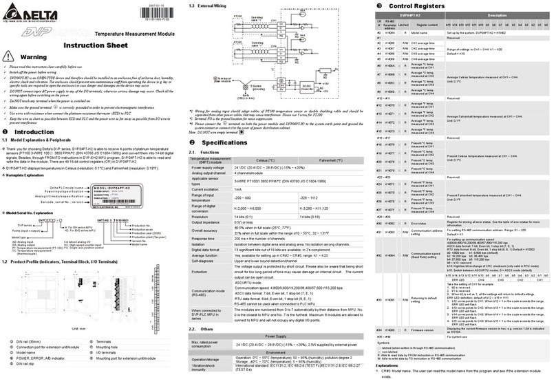
Delta Electronics Platinum Temperature Sensors DVP04PT-S User manual

2009-05-26
5011671201-PT41
DVP-1960530-02

- 1 -
ΞΞΞΞΞΞΞΞΞΞΞΞΞΞΞΞΞΞΞΞΞΞΞΞΞ ENGLISH ΞΞΞΞΞΞΞΞΞΞΞΞΞΞΞΞΞΞΞΞΞΞΞΞΞ
Thank you for choosing Delta DVP series PLC. DVP04PT-S is able to receive 4 points of
platinum temperature sensors (PT 100 3-WIRE 100ȍ3850 PPM/°C (DIN 43760 JIS
C1604-1989)) and convert them into 14-bit digital signals. Besides, through FROM/TO
instructions in DVP Slim series MPU program, the data in DVP04PT-S can be read and
written. There are 49 16-bit control registers (CR) in DVP04PT-S. The power unit is
separate from it and is small in size and easy to install. DVP04PT-S displays
temperatures in both Celsius (resolution: 0.1°C) and Fahrenheit (resolution: 0.1°F).
aPlease read this instruction sheet carefully before use.
aThis is an OPEN TYPE I/O module and therefore should be installed in an enclosure
free of airborne dust, humidity, electric shock and vibration. The enclosure should
prevent non-maintenance staff from operating the device (e.g. key or specific tools
are required for operating the enclosure) in case danger and damage on the device
may occur.
aDO NOT apply AC power to any of the input/output terminals, or it may damage
DVP04PT-S.
aDO NOT touch any terminal when the power is switched on.
aMake sure that the DVP04PT-S is properly grounded , to prevent any
electromagnetic noise.
aPlease keep the wires as short as possible when connecting RTD to PLC and keep
power lead as far away as possible from I/O wires to prevent noise interference.
Product Profile & Dimension
90.00
4.00
3.00 25.20
1
2
3
4
5
Ʌ
FG
L+
L-
I+
C
H
1
C
H
2
C
H
3
C
H
4
Ʌ
FG
L+
L-
I+
FG
L+
L-
I+
FG
L+
L-
I+
60.00 6
7
8
9
3
10
11
12
13
90.00
3.00
3.4 60.00
14
[ Figure 1 ]
Unit: mm
1. Status indicator (POWER, RUN and ERROR) 8. I/O module connection port
2. Model name 9. I/O module clip
3. DIN rail clip 10. DIN rail (35mm)
4. I/O terminals 11. RS-485 communication port
5. I/O point indicator 12. I/O module clip
6. Mounting holes 13. DC power input
7. Specification label 14. I/O module connection port
I/O Terminal Layout
L-L+FGL-L+
DVP04PT-S
FGI- L+FGI-L-L+ FGI-L-I-

- 2 -
External Wiring
PT100
PT100
CH1
CH4
1mA
DC/ DC
5V
AG
+15V
-15V
AG
AG
AG
24+
24-
FG
,
L-
L+
FG
,
L-
L+
Converter
System
Class 3 Grounding
(100 of less)
terminal of
power module
Shielded*1
*2
*3
1mA
Shielded*1
Grounding
[ Figure 2 ]
Note1: Use only the wires that are packed with the temperature sensor (PT100) for analog input
and separate from other power line or any wire that may cause noise. Please use 3-wire
for PT100.
Note2: Terminal FG is grounded for noise suppression.
Note3: Please connect power supply module terminal and DVP04PT-S temperature
measurement module terminal to system earth ground.
Warning: DO NOT connect wires to the No Connection terminals.
Electrical Specifications
DVP04PT-S
Power supply voltage 24VDC (20.4VDC ~ 28.8VDC) (-15% ~ +20%)
Max. rated power
consumption 2W, supplied by external power.
Operation/storage Operation: 0°C~55°C (temp.), 50~95% (humidity), pollution degree 2
Storage: -25°C~70°C (temp.), 5~95% (humidity)
Vibration/shock
resistance
International standards: IEC61131-2, IEC 68-2-6 (TEST Fc)/
IEC61131-2 & IEC 68-2-27 (TEST Ea)
Series connection to
DVP-PLC MPU
The modules are numbered from 0 to 7 automatically by their distance
from MPU. No.0 is the closest to MPU and No.7 is the furthest.
Maximum 8 modules are allowed to connect to MPU and will not
occupy any digital I/O points.
Functional Specifications
DVP04PT-S Celsius (°C) Fahrenheit (°F)
Analog input channel 4 channels per module
Sensors type 3- WIRE PT 100ȍ3850 PPM/°C (DIN 43760 JIS C1604-1989)
Current excitation 1mA
Temperature input range -200°C ~ 600°C -328°F ~ 1112°F
Digital conversion range K-2,000 ~ K6,000 K-3,280 ~ K11,120
Resolution 14 bits (0.1°C) 14 bits (0.1°F)

- 3 -
DVP04PT-S Celsius (°C) Fahrenheit (°F)
Overall accuracy r0.5% of full scale of 25°C (77°F),
r1% of full scale during 0 ~ 55°C (32 ~ 131°F).
Response time 200ms × channels
Isolation method
Isolation between digital and analog circuitry. There is no isolation
between channels.
500VDC between digital circuits and Ground
500VDC between analog circuits and Ground
500VDC between analog circuits and digital circuits
500VDC between 24VDC and Ground
Digital data format 2’s complement of 16-bit
Average function Yes (CR#2 ~ CR#5)
Self diagnostic function Yes
Communication mode
(RS-485)
Yes (CR#32). RS-485 is disabled when the DVP04PT-S is
connected in series with an MPU.
Control Register
CR# Address Save Register content Description
#0 H’4064 O R Model name Set up by the system:
DVP04PT model code = H’8A.
#2 H’4066 O R/W CH1 average number
#3 H’4067 O R/W CH2 average number
#4 H’4068 O R/W CH3 average number
#5 H’4069 O R/W CH4 average number
Number piece of readings used for the
calculation of “average” temperature on
channels CH1 ~ CH4. Setting range:
For versions prior to V3.04: K1 ~ K4,095.
For versions after V3.05: K1 ~ K20.
Default setting is K10.
#6 H’406A X R CH1 average degrees
#7 H’406B X R CH2 average degrees
#8 H’406C X R CH3 average degrees
#9 H’406D X R CH4 average degrees
Average degrees for channels CH1 ~
CH4.
(Unit: 0.1°C).
#12 H’4070 X R CH1 average degrees
#13 H’4071 X R CH2 average degrees
#14 H’4072 X R CH3 average degrees
#15 H’4073 X R CH4 average degrees
Average degrees for channels CH1 ~
CH4.
(Unit: 0.1°F).
#18 H’4076 X R Present temp. of CH1
#19 H’4077 X R Present temp. of CH2
#20 H’4078 X R Present temp. of CH3
#21 H’4079 X R Present temp. of CH4
Present temperature of channels CH1 ~
CH4.
(Unit: 0.1°C).
#24 H’407C X R Present temp. of CH1
#25 H’407D X R Present temp. of CH2
#26 H’407E X R Present temp. of CH3
#27 H’407F X R Present temp. of CH4
Present temperature of channels CH1 ~
CH4.
(Unit: 0.1°F).
#29 H’4081 X R/W PID mode setting Set H'5678 to enable PID mode, other set
values are invalid. Default: H’0000.
#30 H’4082 X R Error status Data register stores the error status.
Refer to the error code chart for details.
#31 H’4083 O R/W Communication
address setting
RS-485 communication address.
Setting range is 01 ~ 254 and default
setting is K1.
#32 H’4084 O R/W Communication baud
rate setting
Communication baud rate (4,800, 9,600,
19,200, 38,400, 57,600 and 115,200bps).

- 4 -
CR# Address Save Register content Description
#32 H’4084 O R/W Communication baud
rate setting
For ASCII mode, date format is 7 bits,
even, 1 stop bit (7, E, 1), while RTU
mode, date format is 8 bits, even, 1 stop
bit (8, E, 1).
b0: 4,800 bps (bit/sec).
b1: 9,600 bps (bit/sec). (default setting)
b2: 19,200 bps (bit/sec).
b3: 38,400 bps (bit/sec).
b4: 57600 bps (bit/sec).
b5: 115,200 bps (bit/sec).
b6 ~ b13: Reserved.
b14: switch between low bit and high bit
of CRC code (RTU mode only).
b15: RTU mode.
b15~b12 b11~ b9 b8~b6 b5~b3 b2~b0
ERR LED CH4 CH3 CH2 CH1
#33 H’4085 O R/W Reset to default
setting
Example: Setting of CH1
1. b0 ~ b1: Reserved.
2. b2: Set to 1 and PLC will be reset to
default settings.
Definition of ERR LED: b12~b15=1111
(default settings)
1. b12 corresponds to CH1: when
b12=1, scale exceeds the range, ERR
LED flashes.
2. b13 corresponds to CH2: when
b13=1, scale exceeds the range, ERR
LED flashes.
3. b14 corresponds to CH3: when
b14=1, scale exceeds the range, ERR
LED flashes.
4. b15 corresponds to CH4: when
b15=1, scale exceeds the range, ERR
LED flashes.
#34 H’4086 O R Software version Display the software version in
hexadecimal. ex: H’010A = version 1.0A
#35 ~ #48 System used
Symbols:
O: means latched. X: means not latched. (Support when using RS-485 communication, not
support when connecting with MPU)
R: able to read data by using FROM instruction or RS-485.
W: able to write data by using TO instruction or RS-485.
ϡThe corresponding parameters address H’4064 ~ H’4086 of CR#0 ~ CR#34 are provided for
users to read/write data via RS-485 communication.
1. Function code: 03’H - read data from register. 06’H - write one word to register. 10’H -
write multiple words to registers.
2. CR#30 is the error code register. Refer to the chart below:
Error description Content b15 ~ b8 b7 b6 b5 b4 b3 b2 b1 b0
Power source abnormal K1 (H’1) 0 0 0 0 0 0 0 1
Wiring to empty external contact K2 (H’2) 0 0 0 0 0 0 1 0
Hardware malfunction K16 (H’10) 0 0 0 1 0 0 0 0
Average times setting error K64 (H’40) 0 1 0 0 0 0 0 0
Instruction error K128 (H’80)
Reserved
1 0 0 0 0 0 0 0
Note: Each error code will have corresponding bit (b0 ~ b7). Two or more errors may
happen at the same time. 0 means normal and 1 means having error.

- 5 -
3. When CR#29 is set to H’5678, CR#0 ~ CR#34 can be used for PID settings in
DVP04PT-S V3.08 and versions above.
PID Mode Content Description
CR#0 Model name CR#17 CH4 KP
CR#2 Output % at CH1 CR#19 CH1 KI
CR#3 Output % at CH2 CR#20 CH2 KI
CR#4 Output % at CH3 CR#21 CH3 KI
CR#5 Output % at CH4 CR#22 CH4 KI
CR#6 CH1 average degrees (°C) CR#24 CH1 KD
CR#7 CH2 average degrees (°C) CR#25 CH2 KD
CR#8 CH3 average degrees (°C) CR#26 CH3 KD
CR#9 CH4 average degrees (°C) CR#27 CH4 KD
CR#10 Set temperature at CH1 CR#28 Run/Stop & Auto turning
CR#11 Set temperature at CH2 CR#29 Enter PID mode(H’5678)
CR#12 Set temperature at CH3 CR#30 Error Code
CR#13 Set temperature at CH4 CR#31 CH1 Sampling time
CR#14 CH1 KPCR#32 CH2 Sampling time
CR#15 CH2 KPCR#33 CH3 Sampling time
CR#16 CH3 KPCR#34 CH4 Sampling time
Temperature/Digital Curve
yTemperature mode (Celsius) yTemperature mode (Fahrenheit)
+6,000
+3,000
-2,000
+600
-200
0
C
C
Digital output
Measured
temperature input
+11,120
+5,560
-3,280
+1,112
-328
0
F
F
Digital output
Measured
temperature input

- 6 -
ΞΞΞΞΞΞΞΞΞΞΞΞΞΞΞΞΞΞΞΞΞΞΞΞ᧯խ֮ ΞΞΞΞΞΞΞΞΞΞΞΞΞΞΞΞΞΞΞΞΞΞΞΞΞΞΞΞ
ტ൞ආشሒ DVP ߓ٨ขΖDVP04PT-S ᄵ৫ၦྒྷᑓิױ൷࠹؆ຝ 4រሬ᥆ᄵ৫
ტྒྷᕴΰPT 100 3 ᒵ100ȍ3850 PPM/°C (DIN 43760 JIS C1604-1989)αΔലհ᠏ངګ
14 ۯցհᑇۯᇆΖຘመ DVP-PLC SS/ SA/SX/SC/SV ᖲ࿓ڤאח FROM/TO ࠐᦰ
ᐊᑓิփհᇷறΔᑓิփࠠڶ 49 ଡCR (Control Register)ᑉژᕴΔޢଡᑉژᕴڶ 16 bitsΖ
ሽᄭցፖᑓิ։ᠦΔ᧯ᗨ՛Δڜᇘ୲࣐Ζࠌشױᙇᖗ᥊ּᄵ৫ΰᙁԵᇞ࣫৫ 0.1°Cα
ࢨဎּᄵ৫ΰᙁԵᇞ࣫৫ 0.1°FαΖ
aᓮڇࠌشհছΔᇡาᔹᦰءࠌشᎅࣔΖ
aءᖲၲ࣋ী (OPEN TYPE) ᖲླྀΔڂڼࠌشࠌشءᖲழΔؘႊലհڜᇘ࣍ࠠ
ቺΕᑪ֗܍࣍ሽᚰбᓢᚰრ؆հ؆ླྀᒵᒣփΖؘႊࠠໂঅᥨൻΰڕΚհ
ՠࠠࢨᨤೲթױؚၲαַፂᥨԳᖙ܂ࢨრ؆ᓢᚰء᧯Δທګٲᙠ֗ჾᡏΖ
aٌᙁԵሽᄭլױຑ൷࣍ᙁԵбנᇆጤΔܡঞױ౨ທګᣤૹჾᡏΔڂڼᓮڇՂሽ
հছ٦ڻᒔᎁሽᄭᒵΖ
aኔᒵΔ೭ؘᣂຨሽᄭΖՂሽழᓮ֎൷ᤛᖲ᧯ጤࢨၞ۩ፂଥΖᙁԵሽᄭ֊ឰ৵Δ
ԫ։ᤪհփΔᓮ֎ᤛփຝሽሁΖ
aء᧯Ղհ൷چጤ ೭ؘإᒔ൷چΔױ༼ขݼᠧಛ౨ԺΖ
aطྒྷᄵ᧯ࠩᄵᓳء᧯ᒵሁᓮش່၏ᠦᒵΔԱᝩ܍ᠧಛ֗ᎈᖄᐙᕣױ౨
ലሽᄭᒵࡉሉᒵ։ၲΖ
!யݡγ៍ᄃొҜ!
yᇡาຝۯقቹፖ؆ᨠ֡՚ᓮᔹ֮ᒘ1հFigure1ΔۯΚmmΖ
1. ሽᄭΕᙑᎄ֗ሎ۩قᗉ 8. I/O ᑓิຑ൷Ց
2. ᖲጟীᇆ 9. I/O ᑓิࡐࡳڬ
3. DIN ૩ࡐࡳڬ 10. DIN ૩ᜊ (35mm)
4. ጤ 11. RS-485 ຏಛՑ
5. ጤᆜ 12. I/O ᑓิࡐࡳᑒ
6. I/O ᑓิࡳۯ֞ 13. ሽᄭᙁԵՑ
7. Ꭾྨ 14. I/O ᑓิຑ൷Ց
!γొቢ!
PT100
PT100
CH1
CH4
1mA
DC/ DC
5V
AG
+15V
-15V
AG
A
G
A
G
24+
24-
FG
I-
L-
L+
FG
I-
L-
L+
᠏ངᕴ
ߓอ൷چរ
รԿጟ൷چ
(100)
൷چݼ אՀ
൷۟ሽᄭᑓ
ิհ ጤ
ሶᠦᒵ
ሶᠦᒵ
*1
*1
*2
*3
1mA
!
ု1Κࠌش࣍ᣊֺᙁԵᒵᚨආشPT100ᄵ৫ტྒྷᕴհຑ൷ᒵࢨᠨሶᠦᒵᚨፖࠡהሽᄭᒵࢨ
ױ౨֧ದᠧಛհ൷ᒵ։ၲΖPT100ᓮࠌش3ᒵڤᄵ৫ტྒྷᕴΖ

- 7 -
ု2Κڕ࣠ᠧಛመՕᓮലFG֗൷چጤຑ൷Ζ
ု3Κᓮലሽᄭᑓิհ ጤ֗DVP04PT-Sᄵ৫ၦྒྷᑓิհ ጤຑ൷ࠩߓอ൷چរΔ٦ലߓอ
൷រ܂รԿጟ൷چࢨ൷ࠩሽᒣհᖲླྀՂΖ
ࣹრΚጤᓮ֎ᒵΖ
!ᏮˢƟᏮბέཉ!
ᓮᔹ֮ᒘ1հጤᆜቹΔڇڼߢءઊฃᎅࣔΖ
!ঈఢ!
DVP04PT-S
ሽᄭሽᚘ 24VDC (20.4VDC ~ 28.8VDC) (-15% ~ +20%)
ᠰࡳ່Օפ 2W, ط؆ຝሽᄭࠎᚨ
ᖙ܂бᚏژᛩቼ 1. ᖙ܂Κ0°C ~ 55°Cΰᄵ৫αΔ50 ~ 95%ΰᛘ৫αΔۆ్ 2
2. ᚏژΚ-25°C ~ 70°Cΰᄵ৫αΔ5 ~ 95%ΰᛘ৫α
ર೯/ᓢᚰ ഏᎾᑑᄷᒤIEC61131-2, IEC 68-2-6 (TEST Fc)/IEC61131-2 & IEC
68-2-27 (TEST Ea)
ፖDVP-PLCᖲ
ۭ൷ᎅࣔ
ᑓิᒳᇆאᔾᖲհႉݧ۞೯ᒳᇆط0ࠩ7Δ່Օױຑ൷8լ۾شᑇ
ۯI/OរᑇΖ
!Αఢ!
DVP04PT-S ᥊ּ (°C) ဎּ (°F)
ᣊֺಛᇆᙁԵຏሐ 4ຏሐб
ᔞٽტᚨᕴݮڤ 3- WIRE PT 100ȍ3850 PPM/°C (DIN 43760 JIS C1604-1989)
ᦀ೯ሽ 1mA
ᙁԵᄵ৫ᒤ -200°C ~ 600°C -328°F ~ 1112°F
ᑇۯ᠏ངᒤ K-2,000 ~ K6,000 K-3,280 ~ K11,120
ᇞ࣫৫ 14 bits (0.1°C) 14 bits (0.1°F)
᜔ࡉ壄യ৫ r0.5% ڇ(25°C, 77°F) ᒤփየࠥ৫ழΖ
r1% ڇ(0 ~ 55°C, 32 ~ 131°F) ᒤփየࠥ৫ழΖ
ᚨழၴ 200ms × ຏሐᑇ
ሶᠦֱڤ
ᑇۯፖᣊֺڶሶᠦΔຏሐၴآሶᠦΖ
ᑇۯሽሁፖ൷چհၴΚ500VDC
ᣊֺሽሁፖ൷چհၴΚ500VDC
ᣊֺሽሁፖᑇۯሽሁհၴΚ500VDC
24VDCፖ൷چհၴΚ500VDC
ᑇۯᇷறڤ 16ۯցԲᇖᑇ
ؓ݁פ౨ ڶ (CR#2 ~ CR#5)
۞ݺ်ឰפ౨ ՂՀᄕૻೠྒྷ/ຏሐ
ຏಛᑓڤ (RS-485) ڶ(CR#32)ΖᅝፖPLCᖲۭ൷ழΔRS-485ຏಛྤࠌشΖ
!ଠטᇶхጡĞ
Ğ
CR
ğ
CR# ᑇ
ۯܿ অী ᑉژᕴټጠ ᎅࣔ
#0 H’4064 O R ᖲጟীᇆ ߓอփࡳΔDVP04PT-Sᖲጟᒳᒘ= H’8AΖ

- 8 -
CR# ᑇ
ۯܿ অী ᑉژᕴټጠ ᎅࣔ
#2 H’4066 O R/W CH1ؓ݁ڻᑇ
#3 H’4067 O R/W CH2ؓ݁ڻᑇ
#4 H’4068 O R/W CH3ؓ݁ڻᑇ
#5 H’4069 O R/W CH4ؓ݁ڻᑇ
ຏሐCH1 ~ CH4ಛᇆؓ݁ڻᑇࡳΚ
V3.04אছءΚױࡳᒤK1 ~ K4,095Ζ
V3.05א৵ءΚױࡳᒤK1 ~ K20Ζ
נᐗࡳଖK10Ζ
#6 H’406A X R CH1ၦྒྷ᥊ּᄵ৫ؓ݁ଖ
#7 H’406B X R CH2ၦྒྷ᥊ּᄵ৫ؓ݁ଖ
#8 H’406C X R CH3ၦྒྷ᥊ּᄵ৫ؓ݁ଖ
#9 H’406D X R CH4ၦྒྷ᥊ּᄵ৫ؓ݁ଖ
ຏሐCH1 ~ CH4ၦྒྷ᥊ּᄵ৫ؓ݁ଖ᧩
قΖۯ0.1°CΖ
#12 H’4070 X R CH1ၦྒྷဎּᄵ৫ؓ݁ଖ
#13 H’4071 X R CH2ၦྒྷဎּᄵ৫ؓ݁ଖ
#14 H’4072 X R CH3ၦྒྷဎּᄵ৫ؓ݁ଖ
#15 H’4073 X R CH4ၦྒྷဎּᄵ৫ؓ݁ଖ
ຏሐCH1 ~ CH4ၦྒྷဎּᄵ৫ؓ݁ଖ᧩
قΖۯ0.1°FΖ
#18 H’4076 X R CH1ၦྒྷ᥊ּᄵ৫ڇଖ
#19 H’4077 X R CH2ၦྒྷ᥊ּᄵ৫ڇଖ
#20 H’4078 X R CH3ၦྒྷ᥊ּᄵ৫ڇଖ
#21 H’4079 X R CH4ၦྒྷ᥊ּᄵ৫ڇଖ
ຏሐCH1 ~ CH4ၦྒྷ᥊ּᄵ৫ڇଖ᧩
قΖۯ0.1°CΖ
#24 H’407C X R CH1ၦྒྷဎּᄵ৫ڇଖ
#25 H’407D X R CH2ၦྒྷဎּᄵ৫ڇଖ
#26 H’407E X R CH3ၦྒྷဎּᄵ৫ڇଖ
#27 H’407F X R CH4ၦྒྷဎּᄵ৫ڇଖ
ຏሐCH1 ~ CH4ၦྒྷဎּᄵ৫ڇଖ᧩
قΖۯ0.1°FΖ
#29 H’4081 X R/W PIDᑓڤࡳ ࡳH’5678ၞԵPIDᑓڤΔࠡהࡳଖઃ
ԫᑓڤΖנᐗࡳଖH’0000Ζ
#30 H’4082 X R ᙑᎄኪ ᚏژࢬڶᙑᎄኪᇷறᑉژᕴΔᇡาփ
୲ᓮᅃᙑᎄஒΖ
#31 H’4083 O R/W ຏಛۯܿࡳ ࡳRS-485ຏಛۯܿΔࡳᒤ01 ~
254ΖנᐗࡳଖK1Ζ
#32 H’4084 O R/W ຏಛຒ (Baud rate)
ࡳ
ץܶASCII/RTUᑓڤΔຏಛຒࡳ٥ڶ
4,800, 9,600, 19,200, 38,400, 57,600,
115,200 bpsքጟΖ
ASCII ᑓڤᇷறڤࡐࡳ7 bitsΕೝۯ
ցΕ1 stop bit (7, E, 1)ΙRTU ᑓڤᇷற
ڤࡐࡳ8 bitsΕೝۯցΕ1 stop bit (8, E,
1)Ζ
b0Κ4,800 bpsΰۯցбઞα
b1Κ9,600 bpsΰۯցбઞαΰנᐗࡳଖα
b2Κ19,200 bpsΰۯցбઞα
b3Κ38,400 bpsΰۯցбઞα
b4Κ57,600 bpsΰۯցбઞα
b5Κ115,200 bpsΰۯցбઞα
b6 ~ b13Κঅఎ
b14ΚCRCᛀᒘ܅ۯٌངΰႛRTUᑓ
ڤڶயα
b15ΚASCII/RTUᑓڤ֊ང

- 9 -
CR# ᑇ
ۯܿ অী ᑉژᕴټጠ ᎅࣔ
b15~b12 b11~ b9 b8~b6 b5~b3 b2~b0
ERRᗉCH4 CH3 CH2 CH1
#33 H’4085 O R/W ༚נᐗࡳ
אCH1ࡳࠐᎅࣔΚ
1. b0 ~ b1অఎΖ
2. b2ࡳ1ழΔࢬڶࡳଖലڃ༚ᐗ
ࡳଖΖ
ERRᗉࡳᆠΚᐗࡳଖb12 ~ b15 = 1111
1. b12ኙᚨCH1Δᅝb12=1ழΔࠥ৫၌መ
ERRᗉೂᡩ೯܂Ζ
2. b13ኙᚨCH2Δᅝb13=1ழΔࠥ৫၌መ
ERRᗉೂᡩ೯܂Ζ
3. b14ኙᚨCH3Δᅝb14=1ழΔࠥ৫၌መ
ERRᗉೂᡩ೯܂Ζ
4. b15ኙᚨCH4Δᅝb15=1ழΔࠥ৫၌መ
ERRᗉೂᡩ೯܂Ζ
#34 H’4086 O R ႇ᧯ء 16ၞࠫΔ᧩قؾছႇ᧯ءΔڕ1.0Aঞ
H’010AΖ
#35 ~ #48 ߓอփຝࠌش
ฤᇆࡳᆠΚ
OقঅীΙXقঅীΖΰܓشRS-485ຏಛ൳ࠫழ֭གΔຑ൷ᖲழլ֭གα
RقױࠌشFROMחᦰ࠷ᇷறΔࢨܓشRS-485ຏಛᦰ࠷ᇷறΖ
WقױࠌشTOחᐊԵᇷறΔࢨܓشRS-485ຏಛᐊԵᇷறΖ
ϡCR#0 ~ CR#34ΚኙᚨհᑇۯܿH’4064 ~ H’4086ױ༼ࠎࠌشܓشRS-485ຏಛᦰᐊᇷறΖ
1. פ౨ᒘ (Function)Κ03’H ᦰנᑉژᕴᇷறΖ06’H ᐊԵԫଡ word ᇷற۟ᑉژᕴΖ10’H ᐊ
Եڍ words ᇷற۟ᑉژᕴΖ
2. CR#30 ᙑᎄኪΚ
ᙑᎄኪ փ୲ଖ b15 ~ b8 b7 b6 b5 b4 b3 b2 b1 b0
ሽᄭฆൄ K1 (H’1) 0 0 0 0 0 0 0 1
൷រ൷ K2 (H’2) 0 0 0 0 0 0 1 0
࿏᧯Ꮍ K16 (H’10) 0 0 0 1 0 0 0 0
ؓ݁ڻᑇࡳᙑᎄ K64 (H’40) 0 1 0 0 0 0 0 0
חᙑᎄ K128 (H’80)
অఎ
1 0 0 0 0 0 0 0
ုΚޢଡᙑᎄኪطઌኙᚨհۯցb0 ~ b7ެࡳΔڶױ౨ᄎٵழขسࠟଡאՂհᙑᎄኪΔ
0זإൄྤᙑᎄΔ1זڶᙑᎄኪขسΖ
3. DVP04PT-S ڇV3.08 אՂءΔᅝ CR#29 ࡳ H’5678 ழΔCR#0 ~ CR#34 ױ
PID ࡳࠌشΚ
PIDᑓڤփ୲ᎅࣔ
CR#0 ᖲጟীᇆ CR#9 CH4 ᥊ּؓ݁ᄵ৫
CR#2 CH1 ᙁנ% CR#10 CH1 ᄵ৫ࡳ
CR#3 CH2 ᙁנ% CR#11 CH2 ᄵ৫ࡳ
CR#4 CH3 ᙁנ% CR#12 CH3 ᄵ৫ࡳ
CR#5 CH4 ᙁנ% CR#13 CH4 ᄵ৫ࡳ
CR#6 CH1 ᥊ּؓ݁ᄵ৫ CR#14 CH1 KP
CR#7 CH2 ᥊ּؓ݁ᄵ৫ CR#15 CH2 KP
CR#8 CH3 ᥊ּؓ݁ᄵ৫ CR#16 CH3 KP

- 10 -
PIDᑓڤփ୲ᎅࣔ
CR#17 CH4 KPCR#27 CH4 KD
CR#19 CH1 KICR#28 Run/Stop & Auto turning
CR#20 CH2 KICR#29 ၞԵPIDᑓڤ (H’5678)
CR#21 CH3 KICR#30 ᙑᎄᒘ
CR#22 CH4 KICR#31 CH1 ࠷ᑌழၴ
CR#24 CH1 KDCR#32 CH2 ࠷ᑌழၴ
CR#25 CH2 KDCR#33 CH3 ࠷ᑌழၴ
CR#26 CH3 KDCR#34 CH4 ࠷ᑌழၴ
!ޘƟᇴҜপّѡቢ!
y᥊ּᄵ৫ၦྒྷᑓڤ yဎּᄵ৫ၦྒྷᑓڤ
+6,000
+3,000
-2,000
+600
-200
0
C
C
ᑇۯᙁנ
ၦྒྷᄵ৫ᙁԵ
+11,120
+5,560
-3,280
+1,112
-328
0
F
F
ၦྒྷᄵ৫ᙁԵ
ᑇۯᙁנ

- 11 -
ΞΞΞΞΞΞΞΞΞΞΞΞΞΞΞΞΞΞΞΞΞΞΞΞΞㅔԧЁ᭛ ΞΞΞΞΞΞΞΞΞΞΞΞΞΞΞΞΞΞΞΞΞΞΞΞΞΞ
ᛳ䇶ᙼ䞛⫼ৄ䖒 DVP ㋏߫ѻકDŽDVP04PT-S ⏽ᑺ⌟䞣ഫৃফ䚼 4⚍䪖䞥ሲ⏽ᑺ
Ӵᛳ఼˄PT 100 3 㒓100ȍ3850 PPM/°C (DIN 43760 JIS C1604-1989)˅ˈᇚП䕀ᤶ៤
14 ԡⱘ᭄ᄫֵোDŽ䗣䖛 DVP-PLC SS/ SA/SX/SC/SV ЏᴎᑣҹᣛҸ FROM/TO ᴹ䇏ݭ
ഫݙⱘ᭄ˈഫݙ᳝ 49 ϾCR (Control Register)ᆘᄬ఼ˈ↣Ͼᆘᄬ఼᳝ 16 bitsDŽ
⬉⑤ܗϢഫߚ⾏ˈԧ⿃ᇣˈᅝ㺙ᆍᯧDŽՓ⫼㗙ৃ䗝ᢽᨘ⇣⏽ᑺ˄䕧ܹߚ䕼⥛Ў 0.1°C˅
⇣⏽ᑺ˄䕧ܹߚ䕼⥛Ў 0.1°F˅DŽ
a䇋Փ⫼Пࠡˈ䆺㒚䯙䇏ᴀՓ⫼䇈ᯢкDŽ
aᴀᴎЎᓔᬒൟ (OPEN TYPE) ᴎˈℸՓ⫼㗙Փ⫼ᴀᴎᯊˈᖙ乏ᇚ݊ᅝ㺙Ѣ䰆ᇬǃ
䰆╂ঞܡѢ⬉ߏކߏᛣⱘ䜡㒓ㆅݙDŽᖙ乏ֱᡸᮑ˄བ˖⡍⅞ⱘᎹ
䩹࣭ᠡৃᠧᓔ˅䰆ℶ䴲㓈ᡸҎ᪡ᛣކߏᴀԧˈ䗴៤䰽ঞᤳണDŽ
aѸ⌕䕧ܹ⬉⑤ϡৃ䖲Ѣ䕧ܹߎֵোッˈ৺߭ৃ㛑䗴៤Ϲ䞡ⱘᤳണˈℸ䇋Ϟ⬉
Пࠡݡ⹂䅸⬉⑤䜡㒓DŽ
aᅲᮑ䜡㒓ˈࡵᖙ݇䯁⬉⑤DŽϞ⬉ᯊ䇋࣓㾺ᴎԧッᄤ䖯㸠㓈ׂDŽ䕧ܹ⬉⑤ߛᮁৢˈ
ϔߚ䩳Пݙˈ䇋࣓㾺ᩌݙ䚼⬉䏃DŽ
aᴀԧϞⱘഄッᄤ ࡵᖙℷ⹂ⱘഄˈৃᦤ催ѻકᡫᑆᡄ㛑DŽ
a⬅⌟⏽ԧࠄ⏽䇗ᴀԧⱘ䜡㒓䏃䇋⫼᳔ⷁ䎱⾏䜡㒓ˈЎњ䙓ܡᑆᡄঞ䇅ᇐⱘᕅડሑৃ㛑
ᇚ⬉⑤㒓䋳䕑䜡㒓ߚᓔDŽ
!யݡγ៍ᄃొҜ!
y䆺㒚䚼ԡᣛ⼎Ϣ㾖ሎᇌ䇋খ䯙㣅᭛⠜义ⷕ1ПFigure1ˈԡ˖mmDŽ
1. 䶣ᄭΕ原冁֗劑۩ق㣼 8. I/O ᑓ㥌劖൷Ց
2. Ẋী㢆 9. I/O ᑓ㥌ࡐࡳڬ
3. DIN 剒ࡐࡳڬ 10. DIN 剒ᜊ (35mm)
4. ጤ 11. RS-485 ຏ允Ց
5. ጤᆜ 12. I/O ᑓ㥌ࡐࡳᑒ
6. I/O ᑓ㥌ࡳۯ֞ 13. 䶣ᄭ剽ԵՑ
7. 即ྨ 14. I/O ᑓ㥌劖൷Ց
!γొቢ!
PT100
PT100
CH1
CH4
1mA
DC/ DC
5V
AG
+15V
-15V
AG
AG
AG
24+
24-
FG
I-
L-
L+
FG
I-
L-
L+
䕀ᤶ఼㋏㒳ഄ⚍
ϝ⾡ഄ
(100)
൷چݼ אՀ
㟇⬉⑤
䱨⾏㒓
䱨⾏㒓
*1
*1
*2
*3
1mA
ഫП ッ
!
⊼1˖Փ⫼Ѣᢳ䕧ܹⱘ䜡㒓ᑨ䞛⫼PT100⏽ᑺӴᛳ఼ⱘ䖲㒓ঠ㒲䱨⾏㒓ϨᑨϢ݊ᅗ⬉⑤㒓
ৃ㛑ᓩ䍋ᑆᡄП㒓ߚᓔDŽPT100䇋Փ⫼3㒓ᓣ⏽ᑺӴᛳ఼DŽ

- 12 -
⊼2˖བᵰᑆᡄ䖛䇋ᇚFGঞഄッᄤ䖲DŽ
⊼3˖䇋ᇚ⬉⑤ഫⱘ ッঞDVP04PT-S⏽ᑺ⌟䞣ഫⱘ ッ䖲ࠄ㋏㒳ഄ⚍ˈݡᇚ㋏㒳
⚍ϝ⾡ഄࠄ䜡⬉ㆅⱘᴎϞDŽ
⊼ᛣ˖ぎッᄤ䇋࣓䜡㒓DŽ
!ᏮˢƟᏮბέཉ!
䇋খ䯙㣅᭛⠜义ⷕ1Пッᄤ䜡㕂ˈℸ䇁㿔⠜ᴀⳕ⬹䇈ᯢDŽ
!ঈఢ!
DVP04PT-S
⬉⑤⬉ 24VDC (20.4VDC ~ 28.8VDC) (-15% ~ +20%)
乱ᅮ᳔⍜㗫ࡳ⥛ 2W, ⬅䚼⬉⑤կᑨ
᪡ټᄬ⦃๗ 1. ᪡˖0°C ~ 55°C˄⏽ᑺ˅ˈ50 ~ 95%˄ᑺ˅ˈ∵ᶧㄝ㑻 2
2. ټᄬ˖-25°C ~ 70°C˄⏽ᑺ˅ˈ5 ~ 95%˄ᑺ˅
㗤ᤃࡼކߏ 䰙ޚ㾘㣗IEC61131-2, IEC 68-2-6 (TEST Fc)/IEC61131-2 & IEC
68-2-27 (TEST Ea)
ϢDVP-PLCЏᴎ
І䇈ᯢ
ഫ㓪োҹ䴴䖥Џᴎⱘ乎ᑣ㞾ࡼ㓪ো⬅0ࠄ7ˈ᳔ৃ䖲8ৄϨϡ⫼᭄
ᄫI/O⚍᭄DŽ
!Αఢ!
DVP04PT-S ᨘ⇣ (°C) ⇣ (°F)
ᢳ䆃ো䕧ܹ䗮䘧 4䗮䘧ৄ
䗖ড়ᛳᑨ఼ᔶᓣ 3- WIRE PT 100ȍ3850 PPM/°C (DIN 43760 JIS C1604-1989)
偅ࡼ⬉⌕ 1mA
䕧ܹ⏽ᑺ㣗ೈ -200°C ~ 600°C -328°F ~ 1112°F
᭄ᄫ䕀ᤶ㣗ೈ K-2,000 ~ K6,000 K-3,280 ~ K11,120
ߚ䕼⥛ 14 bits (0.1°C) 14 bits (0.1°F)
ᘏ㊒ᆚᑺ r0.5% (25°C, 77°F) 㣗ೈݙ⒵ࠏᑺᯊDŽ
r1% (0 ~ 55°C, 32 ~ 131°F) 㣗ೈݙ⒵ࠏᑺᯊDŽ
ડᑨᯊ䯈 200ms × 䗮䘧᭄
䱨⾏ᮍᓣ
᭄ᄫ⬉䏃Ϣᢳ⬉䏃᳝䱨⾏ˈ䗮䘧䯈䱨⾏DŽ
᭄ᄫ⬉䏃ϢഄП䯈˖500VDC
ᢳ⬉䏃ϢഄП䯈˖500VDC
ᢳ⬉䏃Ϣ᭄ᄫ⬉䏃П䯈˖500VDC
24VDCϢഄП䯈˖500VDC
᭄ᄫ᭄Ḑᓣ 16ԡѠ㸹ⷕ
ᑇഛࡳ㛑 ᳝ (CR#2 ~ CR#5)
㞾៥䆞ᮁࡳ㛑 Ϟϟᵕ䰤պ⌟/䗮䘧
䗮䆃ᓣ (RS-485) ᳝(CR#32)DŽᔧϢPLCЏᴎІᯊˈRS-485䗮䆃᮴⊩Փ⫼DŽ
!ଠטхጡĞ
Ğ
CR
ğ
CR# খ᭄
ഄഔ ֱᣕൟ ᆘᄬ఼ৡ⿄ 䇈ᯢ
#0 H’4064 O R ᴎ⾡ൟো ㋏㒳ݙᅮˈDVP04PT-Sᴎ⾡㓪ⷕ= H’8ADŽ

- 13 -
CR# খ᭄
ഄഔ ֱᣕൟ ᆘᄬ఼ৡ⿄ 䇈ᯢ
#2 H’4066 O R/W CH1ᑇഛ᭄
#3 H’4067 O R/W CH2ᑇഛ᭄
#4 H’4068 O R/W CH3ᑇഛ᭄
#5 H’4069 O R/W CH4ᑇഛ᭄
䗮䘧CH1 ~ CH4ֵোⱘᑇഛ᭄䆒ᅮ˖
V3.04ҹࠡ⠜ᴀ˖ৃ䆒ᅮ㣗ೈK1 ~ K4,095DŽ
V3.05ҹৢ⠜ᴀ˖ৃ䆒ᅮ㣗ೈK1 ~ K20DŽ
ߎ咬䅸ؐЎK10DŽ
#6 H’406A X R CH1⌟䞣ᨘ⇣⏽ᑺᑇഛؐ
#7 H’406B X R CH2⌟䞣ᨘ⇣⏽ᑺᑇഛؐ
#8 H’406C X R CH3⌟䞣ᨘ⇣⏽ᑺᑇഛؐ
#9 H’406D X R CH4⌟䞣ᨘ⇣⏽ᑺᑇഛؐ
䗮䘧CH1 ~ CH4⌟䞣ᨘ⇣⏽ᑺᑇഛؐᰒ
⼎DŽԡ0.1°CDŽ
#12 H’4070 X R CH1⌟䞣⇣⏽ᑺᑇഛؐ
#13 H’4071 X R CH2⌟䞣⇣⏽ᑺᑇഛؐ
#14 H’4072 X R CH3⌟䞣⇣⏽ᑺᑇഛؐ
#15 H’4073 X R CH4⌟䞣⇣⏽ᑺᑇഛؐ
䗮䘧CH1 ~ CH4⌟䞣⇣⏽ᑺᑇഛؐᰒ
⼎DŽԡ0.1°FDŽ
#18 H’4076 X R CH1⌟䞣ᨘ⇣⏽ᑺ⦄ؐ
#19 H’4077 X R CH2⌟䞣ᨘ⇣⏽ᑺ⦄ؐ
#20 H’4078 X R CH3⌟䞣ᨘ⇣⏽ᑺ⦄ؐ
#21 H’4079 X R CH4⌟䞣ᨘ⇣⏽ᑺ⦄ؐ
䗮䘧CH1 ~ CH4⌟䞣ᨘ⇣⏽ᑺ⦄ؐᰒ
⼎DŽԡ0.1°CDŽ
#24 H’407C X R CH1⌟䞣⇣⏽ᑺ⦄ؐ
#25 H’407D X R CH2⌟䞣⇣⏽ᑺ⦄ؐ
#26 H’407E X R CH3⌟䞣⇣⏽ᑺ⦄ؐ
#27 H’407F X R CH4⌟䞣⇣⏽ᑺ⦄ؐ
䗮䘧CH1 ~ CH4⌟䞣⇣⏽ᑺ⦄ؐᰒ
⼎DŽԡ0.1°FDŽ
#29 H’4081 X R/W PIDᓣ䆒ᅮ 䆒ᅮH’5678䖯ܹPIDᓣˈ݊ᅗ䆒ᅮؐⱚ
Ўϔ㠀ᓣDŽߎ咬䅸ؐH’0000DŽ
#30 H’4082 X R 䫭䇃⢊ᗕ ټᄬ᠔᳝䫭䇃⢊ᗕⱘ᭄ᆘᄬ఼ˈ䆺㒚ݙ
ᆍ䇋খ✻䫭䇃ֵᙃ㸼DŽ
#31 H’4083 O R/W 䗮䆃ഄഔ䆒ᅮ 䆒ᅮRS-485䗮䆃ഄഔˈ䆒ᅮ㣗ೈ01 ~
254DŽߎ咬䅸ؐЎK1DŽ
#32 H’4084 O R/W 䗮䆃䗳⥛ (Baud rate)
䆒ᅮ
ࣙASCII/RTUᓣˈ䗮䆃䗳⥛䆒ᅮ᳝݅
4,800, 9,600, 19,200, 38,400, 57,600,
115,200 bps݁⾡DŽ
ASCIIᓣ᭄ḐᓣᅮЎ7 bitsǃيԡǃ1
stop bit (7, E, 1)ˈRTUᓣ᭄Ḑᓣᅮ
Ў8 bitsǃيԡǃ1 stop bit (8, E, 1)DŽ
b0˖4,800 bps˄ԡ⾦˅
b1˖9,600 bps˄ԡ⾦˅˄ߎ咬䅸ؐ˅
b2˖19,200 bps˄ԡ⾦˅
b3˖38,400 bps˄ԡ⾦˅
b4˖57,600 bps˄ԡ⾦˅
b5˖115,200 bps˄ԡ⾦˅
b6 ~ b13˖ֱ⬭
b14˖CRCẔᶹⷕ催ԢԡѸᤶ˄ҙRTU
ᓣ᳝ᬜ˅
b15˖ASCII/RTUᓣߛᤶ

- 14 -
CR# খ᭄
ഄഔ ֱᣕൟ ᆘᄬ఼ৡ⿄ 䇈ᯢ
b15~b12 b11~ b9 b8~b6 b5~b3 b2~b0
ERR♃CH4 CH3 CH2 CH1
#33 H’4085 O R/W ᘶߎ䆒ᅮ
ҹCH1䆒ᅮᴹ䇈ᯢ˖
1. b0 ~ b1ֱ⬭Ζ
2. b2 児ࡳ䢠 1㦍Δࢬڶ児ࡳଖ㰒ڃᵵ
ᩈ咬䅸ଖΖ
ERR♃ᅮН˖䆒ᅮؐb12 ~ b15 = 1111
1. b12ᇍᑨCH1ˈᔧb12=1ᯊˈࠏᑺ䍙䖛
ERR♃䮾⚕ࡼDŽ
2. b13ᇍᑨCH2ˈᔧb13=1ᯊˈࠏᑺ䍙䖛
ERR♃䮾⚕ࡼDŽ
3. b14ᇍᑨCH3ˈᔧb14=1ᯊˈࠏᑺ䍙䖛
ERR♃䮾⚕ࡼDŽ
4. b15ᇍᑨCH4ˈᔧb15=1ᯊˈࠏᑺ䍙䖛
ERR♃䮾⚕ࡼDŽ
#34 H’4086 O R 䶻ԧ⠜ᴀ 16䖯ࠊˈᰒ⼎Ⳃࠡ䶻ԧ⠜ᴀˈབ1.0A߭
H’010ADŽ
#35 ~ #48 ㋏㒳ݙ䚼Փ⫼
ヺোᅮН˖
O㸼⼎Ўֱᣕൟ˗X㸼⼎Ў䴲ֱᣕൟDŽ(߽⫼RS-485䗮䆃ࠊᯊᬃᣕˈ䖲Џᴎᯊϡᬃᣕ)
R㸼⼎ЎৃՓ⫼FROMᣛҸ䇏প᭄ˈ߽⫼RS-485䗮䆃䇏প᭄DŽ
W㸼⼎ЎৃՓ⫼TOᣛҸݭ᭄ܹˈ߽⫼RS-485䗮䆃ݭ᭄ܹDŽ
ĆCR#0 ~ CR#34˖ᇍᑨⱘখ᭄ഄഔH’4064 ~ H’4086ৃᦤկՓ⫼㗙߽⫼RS-485䗮䆃䇏ݭ᭄DŽ
1. פ౨东 (Function)Κ03’H 再נബژᕴ䀀⇕Ζ06’H 㡹Եԫ㠺 word 䀀⇕۟ബژᕴΖ10’H 㡹
Եڍ㲶 words 䀀⇕۟ബژᕴΖ
2. CR#30 原冁㦮䬾Κ
䫭䇃⢊ᗕ ݙᆍؐ b15 ~ b8 b7 b6 b5 b4 b3 b2 b1 b0
⬉⑤ᓖᐌ K1 (H’1) 0 0 0 0 0 0 0 1
⚍ぎ K2 (H’2) 0 0 0 0 0 0 1 0
⹀ӊᬙ䱰 K16 (H’10) 0 0 0 1 0 0 0 0
ᑇഛ᭄䆒ᅮ䫭䇃 K64 (H’40) 0 1 0 0 0 0 0 0
ᣛҸ䫭䇃 K128 (H’80)
ֱ⬭
1 0 0 0 0 0 0 0
⊼˖↣Ͼ䫭䇃⢊ᗕ⬅Ⳍᇍᑨⱘԡb0 ~ b7އᅮˈ᳝ৃ㛑Ӯৠᯊѻ⫳ϸϾҹϞⱘ䫭䇃⢊ᗕˈ0
ҷ㸼ℷᐌ᮴䫭䇃ˈ1ҷ㸼᳝䫭䇃⢊ᗕѻ⫳DŽ
3. DVP04PT-S V3.08 ҹϞ⠜ᴀˈᔧ CR#29 䆒ᅮЎ H’5678 ᯊˈCR#0 ~ CR#34 ৃخЎ
PID 䆒ᅮՓ⫼˖
PIDᓣݙᆍ䇈ᯢ
CR#0 ᴎ⾡ൟো CR#9 CH4 ᨘ⇣ᑇഛ⏽ᑺ
CR#2 CH1 䕧ߎ% CR#10 CH1 ⏽ᑺ䆒ᅮ
CR#3 CH2 䕧ߎ% CR#11 CH2 ⏽ᑺ䆒ᅮ
CR#4 CH3 䕧ߎ% CR#12 CH3 ⏽ᑺ䆒ᅮ
CR#5 CH4 䕧ߎ% CR#13 CH4 ⏽ᑺ䆒ᅮ
CR#6 CH1 ᨘ⇣ᑇഛ⏽ᑺ CR#14 CH1 KP
CR#7 CH2 ᨘ⇣ᑇഛ⏽ᑺ CR#15 CH2 KP
CR#8 CH3 ᨘ⇣ᑇഛ⏽ᑺ CR#16 CH3 KP

- 15 -
PIDᓣݙᆍ䇈ᯢ
CR#17 CH4 KPCR#27 CH4 KD
CR#19 CH1 KICR#28 Run/Stop & Auto turning
CR#20 CH2 KICR#29 䖯ܹPIDᓣ (H’5678)
CR#21 CH3 KICR#30 䫭䇃ⷕ
CR#22 CH4 KICR#31 CH1 পḋᯊ䯈
CR#24 CH1 KDCR#32 CH2 পḋᯊ䯈
CR#25 CH2 KDCR#33 CH3 পḋᯊ䯈
CR#26 CH3 KDCR#34 CH4 পḋᯊ䯈
!ޘƟᇴфপّѡቢ!
yᨘ⇣⏽ᑺ⌟䞣ᓣ y⇣⏽ᑺ⌟䞣ᓣ
+6,000
+3,000
-2,000
+600
-200
0
C
C
᭄ᄫ䕧ߎ
䞣⌟⏽ᑺ䕧ܹ
+11,120
+5,560
-3,280
+1,112
-328
0
F
F
䞣⌟⏽ᑺ䕧ܹ
᭄ᄫ䕧ߎ
Other manuals for Platinum Temperature Sensors DVP04PT-S
1
Table of contents
Other Delta Electronics Measuring Instrument manuals
Popular Measuring Instrument manuals by other brands

Midwest
Midwest Model 220 Installation and maintenance instruction

Zeroplus
Zeroplus I2C-SPI user manual

Axio MET
Axio MET AX-5001 user manual

Silvercrest
Silvercrest SND 3600 D2 operating instructions

Blackline Safety
Blackline Safety G7 BRIDGE Technical user's manual

Metrix
Metrix 6850-001 installation manual