2017-12-20
5011624005-I0S5
Warning
EN
IFD8500 is an OPEN-TYPE device. It should be installed in a control cabinet free of airborne dust,
humidity, electric shock and vibration. To prevent non-maintenance staff from operating IFD8500, or to
prevent an accident from damaging IFD8500, the control cabinet in which IFD8500 is installed should
be equipped with a safeguard. For example, the control cabinet in which IFD8500 is installed can be
unlocked with a special tool or key.
EN
DO NOT connect AC power to any of I/O terminals, otherwise serious damage may occur. Please check
all wiring again before IFD8500 is powered up. After IFD8500 is disconnected, Do NOT touch any
terminals in a minute. Make sure that the ground terminal on IFD8500 is correctly grounded in
order to prevent electromagnetic interference.
FR
IFD8500 est un module OUVERT. Il doit être installé que dans une enceinte protectrice (boitier, armoire,
etc.) saine, dépourvue de poussière, d’humidité, de vibrations et hors d’atteinte des chocs électriques.
La protection doit éviter que les personnes non habilitées à la maintenance puissent accéder à
l’appareil (par exemple, une clé ou un outil doivent être nécessaire pour ouvrir a protection).
FR
Ne pas appliquer la tension secteur sur les bornes d’entrées/Sorties, ou l’appareil IFD8500 pourra être
endommagé. Merci de vérifier encore une fois le câblage avant la mise sous tension du IFD8500. Lors
de la déconnection de l’appareil, ne pas toucher les connecteurs dans la minute suivante. Vérifier que la
terre est bien reliée au connecteur de terre afin d’éviter toute interférence électromagnétique.
Introduction
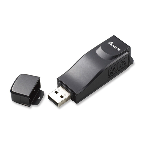
IFD8500 converts RS-232 signals to RS-485/RS422 differential voltage lines for data transmission.
IFD8500 allows you to easily connect a RS-232 device to another RS-485/RS-422 equipment without
changing any hardware or software.
Appearance
DIN rail
RS-232 connector
M3 screw
LED indica tor
RS-485/RS-422&
Power plug in s crew termin al-
Specifications
Power supply +9V ~ +48VDC
Power consumption 0.5W
Isolated voltage 3,000VDC
Baud rate 1,200, 2,400, 4,800, 9,600, 19,200, 38,400, 57,600, 115,200 bps
RS-232 connector 9PIN D-SUB Female
RS-485/RS-422
terminal 10PIN, AWG1-#12 to #24 wires accepted
Dimension (L x W x H) 4.65in x 2.79in x 0.87in (118mm x 71mm x 22mm)
Weight 0.275Ib (125g)
ENGLISH
Installation
Data Format
Set up baud rate and data format to control the data flow.
Baud rate SW1 Baud rate SW1
1 2 3 4 1 2 3 4
1,200bps ON
38,400bps ON
2,400bps ON
57,600bps ON
4,800bps ON
115,200bps ON
** 9,600bps ON RS-422 mode ON
19,200bps ON
Length SW2 Length SW2
1 2 1 2
9 bits ON 11 bits ON
** 10 bits ON 12 bits ON
Notes:** default setting
Calculation of length of data frame:
Length = Start bit + data length + parity bit + stop bit
Example: Data Length = 8 bits, None parity, stop bit = 1 bit, Length = 1 + 8 + 0 + 1 = 10
Termination Resistor
To terminate the cable is system dependent and is affected by the choice of the maximum cable length
and signal rate. The length of RS-485 network cable can be extended to 4,000 ft or 1.2km. It is
necessary to match the line impedance of network to avoid signal distortion by adding to termination
resisters on both ends of RS-485/RS-422 network cable.
Hints for using termination resistor:
a. The longer the transmission cable, the worse the signal quality.
b. Two transmission resistors are recommended to install on both ends of the main cable on the
RS-485/RS-422 network. It is not necessary to add termination resistors on each node in the same
network.
c. If the transmission wire of RS-485 uses 1.2km AWG#24 twisted pair cable, we recommend you
use 120Ωresistor.
Wiring
1. RS-232 (D-SUB 9PIN)
PIN Signal Name PIN Signal Name PIN Signal Name
1 NC 4 NC 7 NC
2 RXD 5 Signal ground 8 NC
3 TXD 6 NC 9 NC
PIN 1-4-6 and 7-8 is short-circuited on the PCB.
2. Power and RS-485/RS-422 (10PIN terminal)
PIN Signal Name PIN Signal Name PIN Signal Name
1 RS-485 DATA+ 5 RS-422 TX- 9 +Vs (Power)
2 RS-485 DATA- 6 RS-422 RX+ 10 GND (ground)
3 Signal ground 7 RS-422 RX-
4 RS-422 TX+ 8 SHLD
Notes:
1. IFD8500 provides 60VDC reverse power protection.
2. To reduce interference, using twisted pair cable is recommended.
Mounting Method
IFD8500 is enclosed with mounting panel*1.
1. DIN Rail
1
2
3
DIN rail
Clip
M3 screw
2. Panel Mount
M3 screw*2
Panel
3. Piggyback
Operation
1. LED display:
a. Green LED On: Power on but no data transmission.
b. Red LED flashing: Data is being transmitted from RS-485/RS-422 to RS-232 port.
c. Green LED flashing: Data is being transmitted from RS-232 to RS-485/RS-422 port.
2. Notes for data transmission on RS-485:
The RS-485 allows for multiple drivers and receivers on single line, facilitating half duplex
communication. Before sending data to RS-485 bus line, make sure that there is no data
transmission on the bus; otherwise you will lose the data.
注意事項
請詳細閱讀下列說明後才使用本產品,以確保使用安全。
由於產品精益求精,當內容規格或驅動程式有所修正時,請洽詢代理商或至台達網站
( http://www.delta.com.tw/product/em/control/cm/control_cm_main.asp )下載最新版本。
產品簡介
本產品主要功能是將 RS-232 信號轉換成 RS-485/RS-422 差動信號,將只有 RS-232 通訊介面的電腦、
PLC 或其他控制器,以本產品轉換成 RS-485/RS-422 介面,從而構成長距離及多點的簡單工業網路。
產品外觀
DIN
軌槽
RS-232
連接埠
M3
特殊螺 絲
LED
指示燈
RS-485/RS-422&
電源輸 入端子台
功能規格
電源需求 +9V ~ +48VDC
消耗功率 0.5 瓦
隔離電壓 3,000VDC
傳輸速度 支援 1,200、2,400、4,800、9,600、19,200、38,400、57,600、115,200 bps
RS-232 端子型式 9PIN D-SUB(母座)
RS-485/RS-422 端子型式 10PIN 端子排,可使用 AWG1-#12 到#24 線
尺寸大小 (長x寬x高) 4.65 英吋 x 2.79 英吋 x 0.87 英吋(118 公釐 x 71 公釐 x 22 公釐)
重量 約125 公克
繁體中文
安裝
資料格式設定
設定傳輸速度及資料格式:
傳輸速度 SW1 設定 傳輸速度 SW1 設定
1 2 3 4 1 2 3 4
1,200 bps ON 38,400 bps ON
2,400 bps ON 57,600 bps ON
4,800 bps ON 115,200 bps ON
** 9,600 bps ON RS-422 模式 ON
19,200 bps ON
資料長度 SW2 設定 資料長度 SW2 設定
1 2 1 2
9位元 ON 11 位元 ON
** 10 位元 ON 12 位元 ON
註:** 為出廠預設值
資料長度計算:
資料長度 = 開始位元長度 + 資料位元長度 + 同位位元長度 + 停止位元長度
例如:資料位元長度 = 8 位元,無同位位元,停止位元長度 = 1 位元
則資料長度 = 1 + 8 + 0 + 1 = 10
終端電阻
當長距離傳輸時,傳輸線的阻抗及電容效應會造成信號的失真與延遲,此時則必須在兩條傳輸線間加入
終端電阻,使阻抗能匹配。
使用終端電阻原則為:
a. 傳輸線過長造成信號傳輸接收不良時。
b. 終端電阻只需接在同一網路點的首端及末端,其餘裝置則不用,如圖例。
c. 1.2 公里雙絞線建議使用 120Ω終端電阻,實際使用仍必須視傳輸線的規格及長度決定。
接線方法
1. RS-232(D-SUB 9PIN)信號腳位定義:
腳位 信號名稱 腳位 信號名稱 腳位 信號名稱
1 NC 4 NC 7 NC
2 RXD 5 信號接地 8 NC
3 TXD 6 NC 9 NC (ring indicator)
PCB 內1-4-6 腳短路,7-8 腳短路
2. 電源、RS-485/RS-422(10PIN 端子排)信號腳位定義:
腳位 信號名稱 腳位 信號名稱 腳位 信號名稱
1 RS-485 DATA+ 5 RS-422 TX- 9 +Vs (電源正端輸入)
2 RS-485 DATA- 6 RS-422 RX+ 10 GND (電源負端輸入)
3 SG(信號接地) 7 RS-422 RX-
4 RS-422 TX+ 8 SHLD
電源(腳位 9、10)可以直流電 9V ~ 48V 提供,正負極性請勿接反,如果不小心接反,本產品可提
供60 伏特逆電壓保護,防止內部電子零件損壞。傳輸線建議使用 AWG1#12 - #24 雙絞線,可提高
信號的穩定度。
固定方式
附件包含嵌板固定板 x 1
1. DIN 軌槽
1
2
3
DIN
軌槽
扣
M3
螺絲
