Accessories
Instruction Sheet
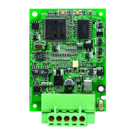
Thank you very much for choosing DTE series accessory. Please read this instruction sheet before using your accessory to
ensure proper operation. Keep this instruction sheet handy for quick reference.
Warning
1. Please hold the plastic terminal when installing the accessory to prevent electrostatic discharge (ESD).
2. Prevent dust or metallic debris from falling into the device and cause malfunction. DO NOT modify or uninstall the
accessory without being permitted. DO NOT use empty terminals.
3. When installing the accessory, please make sure that the power of DTE main unit is switched off and insert the
accessory into the correct slot on DTE main unit.
4. Make sure you install the accessory correctly before switching on the power; otherwise serious damage may occur.
5. DO NOT touch the terminals or repair the device when the power is on; otherwise an electric shock may occur.
Functions & Electrical Specifications
Power
consumption Max. 1.3W
Output
accessories
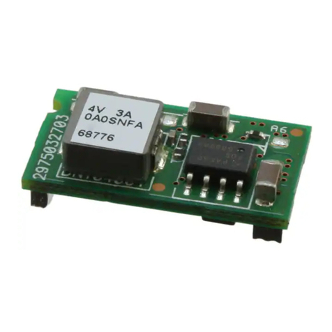
DTE20R: 4 channels of relay output, SPST, max. AC 250V load, 3A resistive load
DTE20V: 4 channels of voltage pulse output, DC 12V +/-10%, max. 40mA current output
DTE20C: 4 channels of current output, DC 4 ~ 20mA output (resistive load < 500Ω)
DTE20L: 4 channels of analog voltage output 0 ~ 10V (resistive load > 1,000Ω)
Input
accessories
DTE2CT: 4 channels of current transformer (CT) input. CT range: 0.5 ~ 30A
Resolution: 0.1A; Offset: ±0.5A
DTE20D: 8 channels of EVENT input. The short circuit resistance of the channel has to be smaller
than 1kΩ; the open circuit resistance has to be bigger than 100kΩ.
Terminal
connection
Current output and analog voltage output boards can only be inserted into main output slots (OUT1,
OUT2) on DTE main unit.
Relay output and voltage output boards can only be inserted into main output slots (OUT1, OUT2) and
sub-output slots (SUB1, SUB2)
CT input and EVENT input boards can only be inserted into the auxiliary slot (AUX) on DTE main unit.
The accessories using for the DTE main unit, please download the DTE10P and DTE10T main unit
operating manual for reference on Delta website.
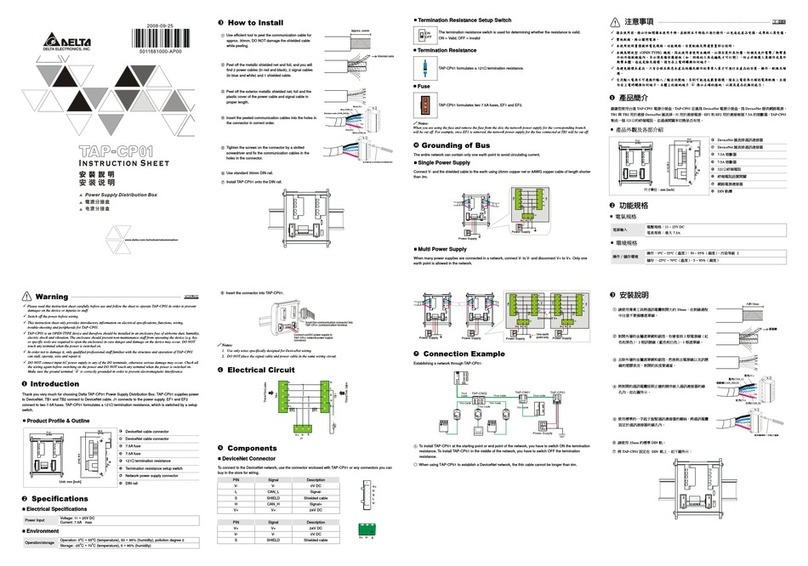
How to Install
Remove all the terminal
blocks on the panel.
Uncover the panel. Make
sure which slot is the
correct one and insert the
accessory into the slot.
Cover up the panel. Insert the terminal blocks
back.
配件安裝手冊
非常感謝您選用台達產品,請在使用前,詳細閱讀本使用說明書,並將手冊放置於易拿處以便參考。
注意事項
1. 安裝時,請握住塑膠端子部分,防止靜電破壞(ESD)。
2. 如果有塵土或金屬殘渣掉入機身,可能會造成誤運行。請勿修改或擅自拆卸電路板。空餘端子請勿使用。
3. 安裝配件電路板時,請先確認主機已斷電,並確認該配件正確的插槽位置。
4. 上電前請確認裝配是否正確及配件電路板到定位,否則可能造成嚴重損壞。
5. 上電時請勿接觸機體端子或進行維修,否則可能遭致電擊。
功能與電氣規格
電源消耗功率 Max. 1.3W
輸出配件種類
DTE20R:4通道繼電器輸出,單刀單閘,最大負載為交流 250 伏特,3安培的電阻性負載。
DTE20V:4通道電壓脈衝輸出,直流 12 伏特+/-10%,最大輸出電流 40 毫安培。
DTE20C:4通道電流輸出,直流 4 ~ 20 毫安培輸出(負載阻抗需小於 500 歐姆)。
DTE20L:4通道類比電壓輸出 0 ~ 10V(負載阻抗需大於 1,000 歐姆)。
輸入配件種類
DTE2CT : 4通道電流檢測輸入,電流檢測範圍 0.5A~30 安培,解析度 0.1 安培,誤差±0.5 安培。
DTE20D:8通道 EVENT 輸入,通道短路電阻必須小於 1k 歐姆,開路電阻必須大於 100k 歐姆。
端子連接功能
電流輸出及類比電壓輸出板僅可插入主機的主輸出 (OUT1、OUT2) 插槽
繼電器輸出及電壓脈衝輸出板可插入主輸出插槽 (OUT1、OUT2) 及次輸出 (SUB1、SUB2) 插槽
電流檢測輸入及 EVENT 輸入板僅可插入主機的輔助 (AUX) 插槽
本配件為配合 DTE 主機使用,請於台達網站下載 DTE10P 及DTE10T 主機操作手冊參考使用。
安裝方式及步驟
移除面板上所有脫落式端
子
掀開面板,確認該配件正
確的插槽位置,插入電路
板至定位。
蓋回面板至定位 裝回脫落式端子至定位
