INSTALLATION SM1500
Page 4 - 3DELTA ELEKTRONIKA B.V. rev. August 2018
8) Ethernet / IEEE488 / RS232 PROGRAMMING
•Set DIP switch 1 on SW1 in position OFF for programming
with the PSC-ETH, the PSC-488 or the PSC-232.
WithDIPswitch1inthisposition,thesignalsVprog(pin11)
and Iprog (pin 3) are disabled on CON E. All the other sig-
nals can still be used. For Ethernet programming CON H
must be used, CON F and G can be used for the user in-
and outputs.
ForIEEE488alsoCONHmustbeusedforprogramming.
For RS232 programming CON F and G must be used.
•Set the unit in REMOTE CV for voltage programming
and/or in REMOTE CC for current programming using the
SCPI commands (see manual PSC) or using the RE-
MOTE/LOCAL button on the unit. Push this button several
times until the right setting is activated. Setting the unit in
REMOTE or LOCAL will cause the output to shutdown to
avoid accidental damage tothe load. Turn it onagain using
theSCPIcommandorwiththeOUTPUTON/OFFbutton.
•Set DIP switch 1 on SW1 in position ON to enable CON E
again for analog programming.
Inthis positionvoltageandcurrentprogramming onCON F
and H is disabled. The other functions and signals can still
be programmed and read back.
9) MONITORING OUTPUTS
•The 5 V level is compatible with most interfaces.
•The monitoring outputs can drive a meter directly
(see fig. 4- 4).
10) STATUS OUTPUTS
•The status outputs have a separate Øconnection (pin 8) to
avoidunwantedoffsetsintheprogramming.Thispinispro-
tectedwitha650mAselfresettingfuse(F27_2onP647).
11) REMOTE SENSING
•Remove the links on the SENSE BLOCK (on rear panel)
and connect sense leads (thin shielded measuring wires)
to S+ and S– (see fig 4- 5 and fig. 4- 6).
•With remote sensing the voltage on the load can be kept
constant. The voltage drop in the load leads will be com-
pensated.Thisfeatureisnotrecommendedfornormaluse,
because it can easily give problems.
•Max. 2 V per load lead can be compensated. Note that the
voltage drop in the leads decreases the max. output volt-
age rating. In fig. 4- 7 it can be seen that on a 15 V power
supply only 11 V will be available on the load when 2x 2 V
compensation is used.
•In order to prevent interference, it is advisable to twist the
sense leads. To minimize the inductance in the load leads
keep the leads close to each other. The inductance of the
loads leads could give a problem with pulsating loads. In
this case a large electrolytic capacitor (Cd) in series with a
dampingresistor(Rd)both in parallel with the load will (see
fig. 4- 6). Check that the capacitor Cd in combination with
theloadleadsandresistorRdformsawelldampedcircuit.
•Since the voltmeter is internally connected to the sensing
terminals, it will automatically indicate the voltage on the
load. Note that the voltage measured on the load will be
lower than on the output terminals.
•TheOver VoltageLimitmeasures thevoltageon theoutput
terminals, so the OVL setting should be increased by the
total voltage drop in the load leads.
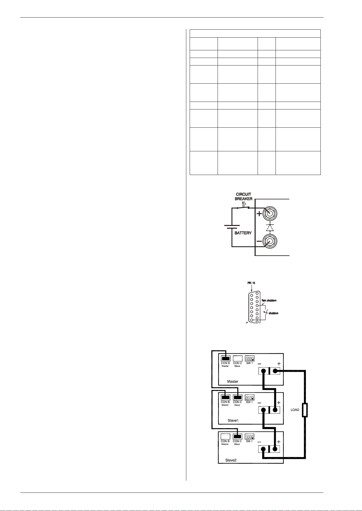
12) BATTERY CHARGER
•The CV / CC regulated power supplies are ideal battery
chargers. Once the output is set at the correct voltage the
battery will charge constantly without overcharging.
This can be useful for emergency power systems.
•Protective measures
Use a CIRCUIT BREAKER in series in order to protect the
power supply from accidental reverse connection (see
fig.4- 8). The circuit breakershould have a DCvoltage rat-
ing twice the battery voltage. Use the very fast type (Z), a
Suggested circuit breakers for protection power supply
Model Type number
circuit breaker Brand Remarks
SM15-100 HTI101 B 100 GE -
SM35-45 S281 UC-Z 50 ABB -
SM52-30 S281 UC-Z 32 ABB extra parallel diode
on output needed
BYV255V-200
SM52AR60 S281 UC-Z 63 ABB extra parallel diode
on output needed
BYV255V-200
SM70-22 S281 UC-Z 25 ABB -
SM120-13 S281 UC-Z 16 ABB extra parallel diode
on output needed
BYV255V-200
SM300-5 S282 UC-Z 6
use with 2 poles
in series
ABB extra parallel diode
on output needed
2xBYT261PIV400
SM400AR8 S282 UC-Z 10
use with 2 poles
in series
ABB extra parallel diode
on output needed
2xBYT261PIV1000
table 4- 2
fig. 4- 8
Charging battery with a circuit breaker in series
fig. 4- 9
Remote ShutDown with switch
fig. 4- 10
Master / Slave series connection


