DELTA ELEKTRONIKA BV SM1500
Page 4 - 3 OPERATING MAINTENANCE TROUBLE SHOOTING CALIBRATING 2005, rev. May 2008
This feature is not recommended for normal use, because
it can easily give problems.
•Max. 2 V per load lead can be compensated. Note that the
voltage drop in the leads decreases the max. output volt-
age rating. In fig. 4 - 7 it can be seen that on a 15 V power
supply only 11 V will be available on the load when 2x 2 V
compensation is used.
•In order to prevent interference, it is advisable to twist the
sense leads. To minimize the inductance in the load leads
keep the leads close to each other. The inductance of the
loads leads could give a problem with pulsating loads. In
this case a large electrolytic capacitor (Cd) in series with a
damping resistor (Rd) both in parallel with the load will (see
fig. 4 - 6). Check that the capacitor Cd in combination with
the load leads and resistor Rd forms a well damped circuit.
•Since the voltmeter is internally connected to the sensing
terminals, it will automatically indicate the voltage on the
load. Note that the voltage measured on the load will be
lower than on the output terminals.
•The Over Voltage Limit measures the voltage on the output
terminals, so the OVL setting should be increased by the
total voltage drop in the load leads.
9) BATTERY CHARGER
•The CV / CC regulated power supplies are ideal battery
chargers. Once the output is set at the correct voltage the
battery will charge constantly without overcharging.
This can be useful for emergency power systems.
•Protective measures
Use a CIRCUIT BREAKER in series in order to protect the
power supply from accidental reverse connection (see
fig. 4 - 8). The circuit breaker should have a DC voltage rat-
ing twice the battery voltage. Use the very fast type (Z), a
type meant for protecting semiconductors (see table 4 - 2).
The unit has a reverse diode in parallel with the output, this
diode and the wiring cannot withstand the thousands of
amperes supplied by a wrongly connected battery.
10) REMOTE SHUTDOWN
•The Remote ShutDown can be operated on CON E by a
voltage of +4 V...+12 V or by a relay contact between Vref
and Remote ShutDown (pin 9 and 5) (see fig. 4 - 9).
•When the unit is programmed with an optional PSC, a
software command can be used for Remote ShutDown.
•In the Remote ShutDown condition, the RSD LED will light.
The DCF LED, DCF status and the DCF relay will be off.
Important: If the link from the Interlock connector (CON A)
has been removed, the RSD LED will be on, but in this
condition also the DCF LED, the DCF status and the DCF
relay will be on.
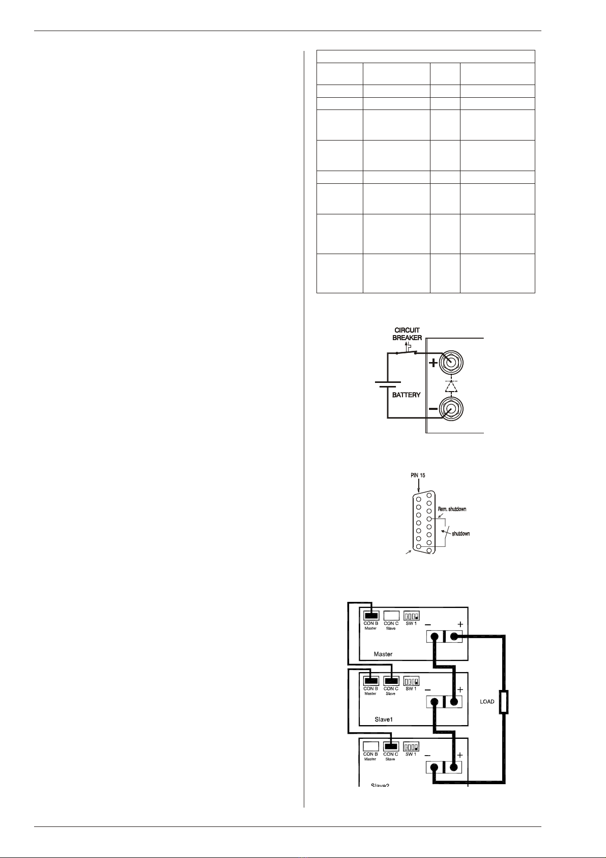
11) MASTER / SLAVE SERIES OPERATION
•Connect output terminals and test system in normal
series operation. Ensure that all (output) power connec-
tions are reliable.
•The voltage drop in the connecting leads between the units
should be kept < 10 mV.
•Switch off all units. Connect units as shown in fig. 4 - 10.
To connect the slaves with the master via CON B and CON
C, use standard UTP cables (RJ45).
On all units put DIP switch 4 of SW1 in position OFF to set
the units in M/S series mode.
•After turning the units on again, the slaves will be in Remote
CV mode and the Keylock, see previous paragraph 2) is ac-
tivated. This is because the unit automatically detects the
presence of the RJ45 connector in CON C (if this cable is
connected to another unit).
If the RJ45 connector is removed from CON C when the
unit is turned on, the output will shutdown to avoid
accidental damage.
Suggested circuit breakers for protection power supply
Model Type number
circuit breaker
Brand Remarks
SM15-100 HTI101 B 100 GE -
SM35-45 S281 UC-Z 50 ABB -
SM52-30 S281 UC-Z 32 ABB extra parallel diode
on output needed
BYV255V-200
SM52AR60 S281 UC-Z 63 ABB extra parallel diode
on output needed
BYV255V-200
SM70-22 S281 UC-Z 25 ABB -
SM120-13 S281 UC-Z 16 ABB extra parallel diode
on output needed
BYV255V-200
SM300-5 S282 UC-Z 6
use with 2 poles
in series
ABB extra parallel diode
on output needed
2xBYT261PIV400
SM400AR8 S282 UC-Z 10
use with 2 poles
in series
ABB extra parallel diode
on output needed
2xBYT261PIV1000
table 4 - 2
Circuit breakers for protection.
fig. 4 - 8
Charging battery with a circuit breaker in series
fig. 4 - 9
Remote ShutDown with switch
fig. 4 - 10
Master / Slave series connection


