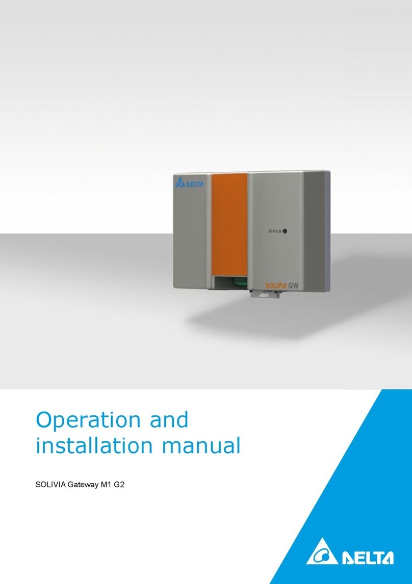
Delta Energy Systems SOLIVIA Gateway M1 G2 Specification sheet

Operation and
installation manual
SOLIVIA Gateway M1 G2


1Operation and installation manual SOLIVIA Gateway M1 G2
ENGLISH
The manual is subject to change.
Please check our website at www.solar-inverter.com
for the most up-to-date manual version.
© Copyright – Delta Energy Systems (Germany) GmbH - All rights reserved.
This manual accompanies our equipment for use by the end users.
The technical instructions and illustrations contained in this manual are to be treated as condential and no part may be reprodu-
ced without the prior written permission of Delta Energy Systems Service engineers and end users may not divulge the information
contained herein or use this manual for purposes other than those strictly connected with correct use of the equipment.
All information and specications are subject to change without notice.

2 Operation and installation manual SOLIVIA Gateway M1 G2

3Operation and installation manual SOLIVIA Gateway M1 G2
ENGLISH
1 About this Manual 4
1.1 Purpose of this Manual 4
1.2 Warnings and Symbols 4
2 Intended Use 5
3 General Safety Instructions 5
4 Scope of Delivery 6
5 Planning 6
5.1 Items / Tools Required for Installation 6
5.2 Further Requirements 6
6 Connector Positions 7
7 Installation Procedure 8
7.1 Registration 8
7.2.1 Mounting on a DIN Rail 8
7.2.2 Mounting Directly to the Wall 9
7.3 RS485 Connection 9
7.4 Ethernet Connection 9
7.5 Connection of the Ripple Control Receivers 9
7.6 Power Connection 11
8 LED Status 12
9 Troubleshooting RS485 / Ethernet Communication 12
10 Configuration through Web Server 12
10.1 Access the Configuration Web Server 13
10.2 First Log in 14
10.3 Network Settings 14
10.4 Connection Settings 15
10.4.1 RS485 Bus Communication 16
10.4.1.1 Wireless RS485 Modem 16
10.4.2 Delta Database Connection 16
10.4.3 Force RS485 Bus Scan 16
10.4.3.1 List of Connected SOLIVIA Solar Inverters 16
10.4.4 Force Gateway Reset 17
10.4.5 Restart Gateway 17
10.5 Digital Inputs 17
10.5.1 Power Management 18
10.5.2 Power Factor Control 18
10.6 Power Balancing 19
10.6.1 Configuration 19
10.6.1.1 Feature Activation 20
10.6.1.2 Power Balancing Requested from the Public Grid Supplier 20
10.6.1.3 Grid Assignment 20
10.6.2 Balancing 20
10.7 Inverter Information 21
11 Delta Service Software 22
12 Reset Button 22
13 Product Specification 23
14 Certificates 49

4 Operation and installation manual SOLIVIA Gateway M1 G2
Congratulations on the purchase of the SOLIVIA Gateway M1 G2.
These directions will help you become familiar with this product. Please observe the
safety regulations of the individual countries. Careful handling of your product will con-
tribute to its service life durability and reliability.
This manual is part of the product and is only valid for the SOLIVIA Gateway M1 G2.
Keep this manual in a safe place.
Read this manual carefully and follow the instructions given in this manual. This man-
ual contains important information for installing and operating the gateway.
Observe and follow the information for safe use (please refer to Chapter 3).
Both the installer and the operator must have access to this manual and must be famil-
iar with the safety instructions.
Here, you will nd explanations for the warnings and symbols used in this
manual:
Indicates a hazardous situation, that could result in pro-
perty damage.
Indicates a hazardous situation. If not prevented, an acci-
dent result in moderate or minor injury to humans.
Indicates a hazardous situation. If not prevented, an
accident result in death or serious injury to humans.
Indicates a hazardous situation. If not prevented, an acci-
dent result in death or serious injury to humans.
This symbol warns of the dangers of electric shock
due to high electrical voltage.
This symbol warns against a general danger.

5Operation and installation manual SOLIVIA Gateway M1 G2
ENGLISH
The SOLIVIA gateway is the interface between your SOLIVIA inverter and the SOLIVIA
Monitor web portal. It transmits all relevant data from your SOLIVIA inverter (for exam-
ple the supplied AC energy of the day, the actual AC power, some error bytes etc.) to
the SOLIVIA Monitor web portal. It allows you continuous monitoring of your PV system
from anywhere that you have internet access.
The SOLIVIA gateway must be used indoors with IP20 environmental conditions.
The SOLIVIA gateway must only be operated according to its intended use.
Please observe the safety regulations of the individual countries. Careful handling of
your product will contribute to its service life durability and reliability. These are essen-
tial pre-requisites for maximum yield from your product.
• Inappropriate handling can lead to physical injury and material damage!
• Do not remove warning labels that have been attached to the SOLIVIA gateway
by the manufacturer.
• Observe all points in this installation and operation manual!
• Repair work on the device may be carried out by the manufacturer only.
• For a safe and normal operation of the SOLIVIA gateway, it is absolutely
necessary that the gateway is installed and operated according to this manual
(see IEC 62109-5.3.3).
• Delta Energy Systems is not responsible for damage caused by failure to observe
the operation and installation instructions in this manual.
In order to avoid damage to property or personal injury,
only qualied, trained electricians may work on the equip-
ment. The qualied electrician must familiarise himself/
herself with this manual.
Do not dispose of electrical appliances as unsorted
municipal waste, use separate collection facilities.
Contact your local government for information regarding
the collection systems available. If electrical appliances
are disposed of in landlls or dumps, hazardous sub-
stances can leak into the groundwater and get into the
food chain, damaging your health and well-being. When
replacing old appliances with new once, the retailer is
legally obligated to take back your old appliance for dis-
posal at least for free of charge.

6 Operation and installation manual SOLIVIA Gateway M1 G2
• SOLIVIA Gateway M1 G2
• AC power plug (3 adapters for usage in different countries)
• Operation and installation manual
• Label
Following items and tools are required for installation but are not included to the
SOLIVIA gateway box. Please make sure to have them available before starting instal-
lation.
• 1 standard twisted pair Ethernet cable
•
The Ethernet cable should meet or exceed the standard CAT5 and should not exceed
a length of 100 m. These standard twisted pair Ethernet cable can be purchased for
your installation at many electronics and ofce supply retailers. The gateway requires
a shielded cable STP, FTP, S/FTP or S/STP.
1 RS485 communication interface cable
•
The RS485 cable should meet the protection class IP65. We recommend using the
RS485 cable from Harting (Part Number: 09 45 145 1560). Cable lengths should not
exceed 1200 m if Baud rate is 19200 (default value). The required cable quality is the
same as for the Ethernet connection: at least shielded (STP, FTP, S/FTP or S/STP)
CAT5 cable or better.
2 screws are required to mount the gateway directly to the wall:
»Nominal diameter: 4 mm
»Maximum head diameter: 9 mm
»Maximum height of head: 3 mm
• Screwdriver (if gateway should be mounted to the wall); size of the screwdriver
depends on used screws
The SOLIVIA gateway must be installed only indoors according to protection class
IP20.
If more than one SOLIVIA solar inverter will be connected in a chain, ensure that
each inverter has a unique ID assigned in the solar inverter user interface.

7Operation and installation manual SOLIVIA Gateway M1 G2
ENGLISH
• Please check the SOLIVIA solar inverter manual for instructions on how to select
the inverter ID.
• The gateway must have an AC power outlet within 2 meters of the gateway.
Please make sure, that DHCP is activated at your router, so that the IP address of
your gateway is automatically found. If DHCP is disabled at your router the gateway
uses the default IP conguration. For further information, please refer to Chapter 10.3
GW
STATUS
RESET RS485
EXT. CONTROL
1 2 3 4 5 6 7 8 A B LAN INPUT
5V
RESET For detailed information, please refer to Chapter 7.8
RS485 Connection of your SOLIVIA inverter with the
SOLIVIA gateway.
EXT. CONTROL Ripple control receivers control the power management (power
limitation) and the power factor (cos ϕ).
LAN Connection of your SOLIVIA gateway with an internet connected
network point.
INPUT 5V Gateway power supply connector.
Status LED

8 Operation and installation manual SOLIVIA Gateway M1 G2
First register for a SOLIVIA Monitor user account on the web at: http://register.solivia-
monitor.com. After registering you will receive, via email, a user name, a password,
and a link to a Conguration Wizard that will allow you to set up and monitor your site
from the SOLIVIA Monitor web portal. Complete the Conguration Wizard setup before
installing the monitoring hardware. In this way, you can go to the web portal after the
hardware installation and verify everything is working correctly.
At the install site, verify the internet connection is active by connecting a laptop to the
internet connected network point and pointing a web browser to www.solar-inverter.
com.
Mount the SOLIVIA gateway with the appropriate AC power location specied in Chap-
ter 5.2. You have either the possibility to mount the SOLIVIA gateway on a DIN rail or
directly to the wall.
The gateway can be mounted on the following DIN Rails:
• DIN Rail according to EN60715 TH35-15
• DIN Rail according to EN60715 TH35-7.5
The gateway should be installed horizontally with connectors on the bottom.
To mount, snap the gateway on the DIN rail as shown in Figure 1:
1. Pull the gateway's DIN rail latch OUT.
2. Tilt the unit slightly upwards, hook the top end onto the DIN rail and push down-
wards until stopped.
3. Position the bottom front end against the DIN rail until it has snapped onto the DIN
rail.
4. Push the gateway's DIN rail latch IN to lock.
2
1
2
3
4
Figure 1: Mounting the gateway on a DIN rail

9Operation and installation manual SOLIVIA Gateway M1 G2
ENGLISH
To dismount, pull the gateway's DIN rail latch OUT. Then, tilt the bottom part of the unit
out, push the unit up and pull out from the DIN rail.
Mount the gateway with appropriate screws to the wall
Use the 2 screws specied in Chapter 5.1 to mount the gateway with the DIN Rail to
the wall. Center-to-center distance between the two boreholes is 70 mm.
70 mm
Figure 2: Mounting the gateway directly to the wall
Connect a standard CAT cable between the RS485 connector on the SOLIVIA gateway
and the RS485 connector on the SOLIVIA solar inverter. See step 1 in gure 4 below.
Connect an Ethernet network cable between the SOLIVIA gateway and the internet
connected network point. See step 2 in gure 4.
You are able to connect the digital inputs to a given function. This concerns the control
of the power the inverter feeds to the grid (power management) and of the power factor
(reactive power control).
If your local public grid supplier requires a remote power derating capability, this can
be implemented by using a ripple control receiver. Please connect the ripple con-
trol receiver as shown in gure 3. After the conguration as shown in Chapters 10.5
and 10.6 the public grid supplier is capable to remotely limit the maximum power the
SOLIVIA solar inverters provide to the public grid.

10 Operation and installation manual SOLIVIA Gateway M1 G2
The ripple control receiver that controls the power management (power limitation) has
to be connected to the inputs 1 to 4. The receiver that controls the power factor (cos
phi) has to be connected to the inputs 5 to 8.
After connection of the ripple control receiver(s) the gateway has to be congured in
order to do the required control of the SOLIVIA solar inverters. For further information,
please refer to Chapters 10.5 and 10.6.
Of course it is also possible to connect only one ripple control receiver, i. e. the one that
controls the power management.
Figure 3: Ripple control receivers circuit diagram
The cables connecting the SOLIVIA gateway with the ripple control receiver(s) should
meet the following specications:
• Max. conductor cross-section: 0.5 mm2 (AWG20)
• Min. conductor cross-section: 0.14 mm2 (AWG26)
• Tightening torque: 0.12 – 0.15 Nm
• Max. cable length: 2 m

11Operation and installation manual SOLIVIA Gateway M1 G2
ENGLISH
Connect the power source to the SOLIVIA gateway (Step 3 in gure 4) and check the
SOLIVIA gateway LED. If the setup is correct, the Status LED will be solid green for
approx. 5 seconds. For further information, please refer to Chapter 8.
Verify that your setup is successful by going to the SOLIVIA Monitor web portal at:
http://www.solivia-monitor.com and log in to view your PV system.
Internet
RS485
RS485
RESET RS485
EXT. CONTROL
1 2 3 4 5 6 7 8 A B LAN INPUT
5V
GW
STATUS
2
3
1
Figure 4: Connection diagram
Risk of death or heavy injury due to dangerous voltage
► Repairs on defective cables should be done by quali ed electri-
cians only!
► Only recommended and / or commercially available cables
should be used.
This function works only for SOLIVIA solar inverters of the 4th generation!

12 Operation and installation manual SOLIVIA Gateway M1 G2
After installation, the gateway checks the connection to the Ethernet and to the inverter.
• If the Ethernet connection (connection to the internet resp. web portal) works, the
gateway sends a message to the inverter. The following message appears on the
display of the inverter: "Portal Connection ok".
• If the Ethernet connection is not working, the following message appears on the
display of the inverter: "No Portal Connection":
Both messages will be displayed for 120 sec.
If the message "No Portal Connection" appears on the display, please check the Ether-
net connection of the gateway and your internet connection.
If no message appears on the display, please check the RS485 connection between
gateway and inverter and ensure that all inverters have unique RS485 bus IDs.
The gateway has one single LED visible on top of the housing of the gateway. After
power up, it immediately starts scanning for connected inverters. So the LED is con-
stantly ON (no blinking) until the scan is nished.
After that the LED change to one of the following behaviors:
Constantly ON (no blinking) Neither Ethernet nor inverter connection.
Fast blinking (300 ms) Ethernet connection but no inverter connection.
Slow blinking (1 s) No Ethernet connection but inverter connection.
Hinking 200 ms on,
1800 ms off Ethernet as well as inverter connection is online.
Extremely fast blinking Indicates for one second that the reset button has been
pressed.
If one connection (Ethernet or RS485) works, try to exchange the cables. If now the
other interface works it is very likely that one cable is broken.
The HTTP-server implements a browser interface allowing you to congure the gate-
way and to display several information. The features are:
• Log in
• Conguration
• Display information about inverters

13Operation and installation manual SOLIVIA Gateway M1 G2
ENGLISH
To access the conguration tool, you have to install the software program
"IP Resolver" that you can download from our website: www.solar-inverter.com.
Please make sure, that your internet connection is active!
Once installed, start the program by double-click.
The following window will open:
In case that the IP address is not immediately found, click on the "rescan" button.
Then, double-click on the IP address in the "IP Resolver" to open the web server.
The log in window will open:
If your network do not work with DHCP, please proceed as follows:
1. Congure your computer settings manually to 192.168.0.199
2. Open your web browser
3. Insert IP http://192.168.0.200/
4. Now go to Chapter 10.3 to see how you congure the IP of the SOLIVIA gateway.

14 Operation and installation manual SOLIVIA Gateway M1 G2
If you log in to the conguration web server for the rst time, please enter the following
log in data:
• Default Username: Delta
• Default Password: 000000
Then, click the "Log in" button.
If you leave the server untouched for more than ve minutes, it is logged out automati-
cally and any access will provide the log in page.
As you log in for the rst time, you will be asked to change your log in data for security
reasons.
The following window will automatically open:
• Change your log in data by following the instructions given and click on the
"Submit" button.
• After submitting your new data, the following message will conrm your changes:
"Operation successfully completed!"
If your router is not supporting DHCP, you will have to enter the IP address of your
SOLIVIA gateway manually.
Click on "Network Settings" on the left side to open the following window where you
can enter your network parameters:

15Operation and installation manual SOLIVIA Gateway M1 G2
ENGLISH
By default the gateway is congured to get its IP address from a DHCP server.
To conrm your entering, click the "Submit" button.

16 Operation and installation manual SOLIVIA Gateway M1 G2
Here you can set the baud rate of the gateway for the RS485 communication. The
value should match the one of the inverter(s). The baud rate "19200" is set by default.
Please note, that the RS485 cable lengths is depending on the baud rate. Cable
lengths should not exceed 1200 m if baud rate is 19200 (default value).
If you are using a RS485 wireless modem, please check the box.
Every few seconds, the gateway is retrieving data from the SOLIVIA solar inverters.
The gateway stores these data and sends the average values to the database. Here
you can dene the intervals in minutes of how often the average values and param-
eters are sent to the database. By default, 15 minutes is set.
The gateway does not know the number and addresses of connected inverters in
advance. It is assumed that each inverter connected to the bus already has its unique
address in the range [1, 254]. Address 0 is not allowed and 255 is the value used for
broadcasts.
Please check the SOLIVIA inverter user manual for instructions on how to select the
inverter ID.
Usually the list of inverters gets only longer. Every inverter that was once detected by
the gateway will remain in this list. By pressing the "Start" button the list will be can-
celled and the RS485 bus will be scanned for connected inverters.
The gateway is designed to connect to a maximum of 32 devices.
At power-up, start-up and each day at about noon the gateway scans the RS485 bus
for all connected SOLIVIA solar inverters.
• Start from address 1 up to address 254. Address 0 is invalid and address 255 is
the broadcast address.
During the usual operation the gateway collects only the data of the inverters in the
inverter list. If a new inverter is connected at e.g. 2:00 pm, this inverter will only be re-
cognized after a new scan (latest the next day at about noon).

17Operation and installation manual SOLIVIA Gateway M1 G2
ENGLISH
To reset the gateway to production settings press either the reset switch for more than
5 seconds or click on the "Reset" button. After reset of the gateway, the default values
shall become used again requiring a new conguration if needed.
All the inverter data are cleared, the device is reset and a new RS485 bus
scan starts, ending with a ash store. The settings of Power Balancing,
Power Management, Power Factor Control, Baud-rate and send interval
remain unchanged.
By pressing the "Restart" button the gateway will be restarted. This restart has no
impact on any congurations set before.
The SOLIVIA gateway gives a voltage to the output A and measures the inputs 1 to 8.
In this way the SOLIVIA gateway can detect the state of the relays of the ripple control
receivers. The information which relay shall control what parameter has to be commu-
nicated by the public grid supplier.
Example: Information from the public grid supplier: If relay 2 is closed then the power
factor (cos ϕ) shall be set to 0.93 capacitive, if relays 1 and 2 are closed then the power
factor shall be set to 0.98 inductive.
If the reactive power control receiver is connected to the SOLIVIA gateway as shown
in gure 3 (Chapter 7.5) then the “Power Factor Control” should be congured like in
gure 5.

18 Operation and installation manual SOLIVIA Gateway M1 G2
There are four binary inputs that control the maximum power the inverter may feed into
the grid.
Power management is at 100 % for all relay state combination except 60 % for relay 1,
30 % for relay 2, and 0 % for relay 3 (default settings).
The power factor conguration page allows the denition of 15 values for the cos φ,
either inductive or capacitive. If all inputs are inactive the cos φ is 1.00.
The values are entered in the form 0.xx, e.g. 0.95 and a checkbox decides whether it is
leading current (capacitive) or not.
Please remember to save the congurations by pressing the “Submit” button.
1) This chapter is only relevant for countries, in which your public grid supplier requires a power reduction
(power management), power factor control and/or power balancing.
Other manuals for SOLIVIA Gateway M1 G2
1
Table of contents
Languages:
Other Delta Energy Systems Gateway manuals
Popular Gateway manuals by other brands
IMesh X
IMesh X Probe S Series Configuration guide

ZyXEL Communications
ZyXEL Communications ZyXEL ZyWALL 10W quick start guide

Huawei
Huawei DG8245V quick start
FieldServer
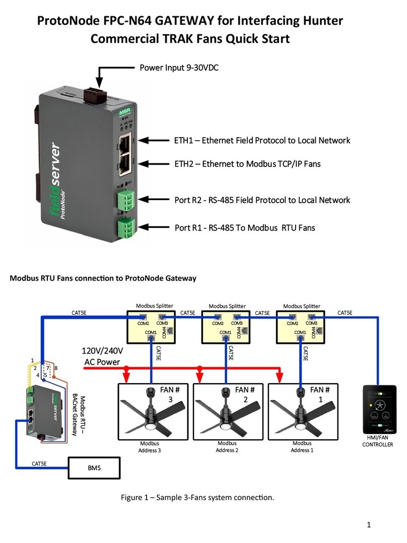
FieldServer ProtoNode FPC-N64 quick start
Danfoss
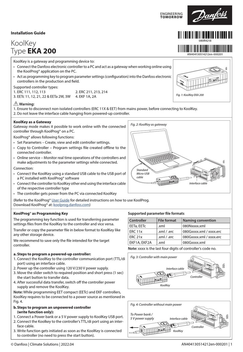
Danfoss KoolKey EKA 200 installation guide
AT&T
AT&T U-verse TV Self-installation guide
