Delta Regis DRFF-300R User manual

Automatic Screw Feeder
User Manual
Y2F152-1-002
DRFF-300R
Delta Regis Tools Inc.
7370 Commercial Circle
Fort Pierce, FL
34951
1-888-500-2755
www.deltaregis.com

Before the use of theAutomatic Screw Feeder, please read the
following carefully:
◎Before the use, please be sure to install the machine at a location of solid foundation, and the
machine shall not be subject to any conditions of tilting left or right and elevated front or rear
in order to prevent impacts on the normal operation.
◎During the use of the machine, the machine shall be grounded.
◎If the machine is not used for a long period of time, the power shall be shut down and the
power plug shall be removed.
◎Please be sure to use the transformer provided by the original manufacturer in order to prevent
damages of the machine and impacts on the normal operation.
◎The inner tracks inside the machine are essential components; therefore, please do not damage
or contaminate such parts.
◎Before switching on, please ensure that the screws placed in the machine match with the
specification of the sliding track. Please do not place contaminated screws, foreign objects and
mismatched screws into the machine.
◎During the operation of the machine, please do not place hand or insert foreign object or pour
materials into the container tank.
◎During the operation of the machine, in case of any malfunction or abnormal sounds, please
shut down the power immediately, and perform inspection after removing the power plug.

Table of Contents
Check before Use................................................................................................................................1
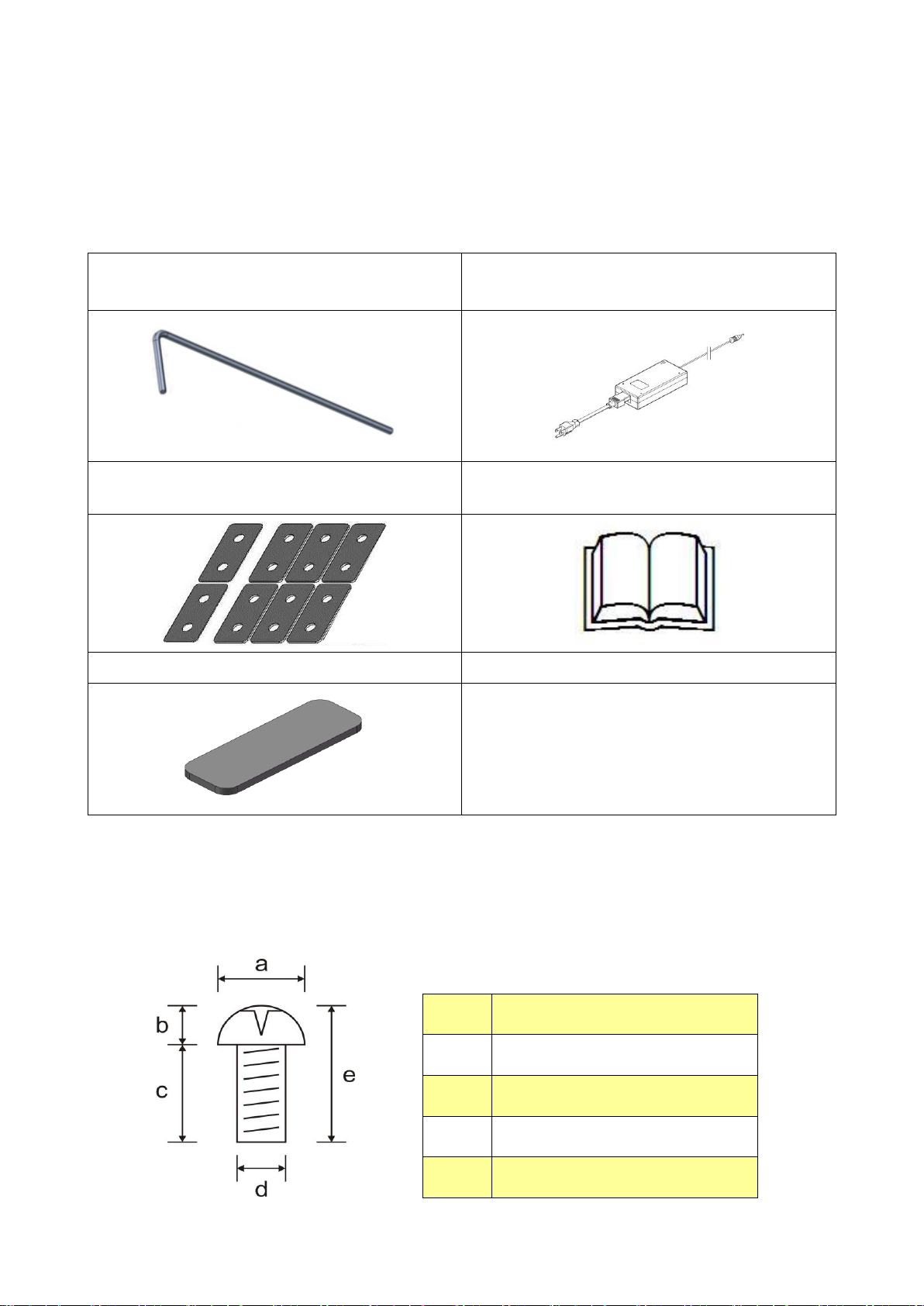
Equipped Accessories ..................................................................................................................1
Check Screw Dimension..............................................................................................................1
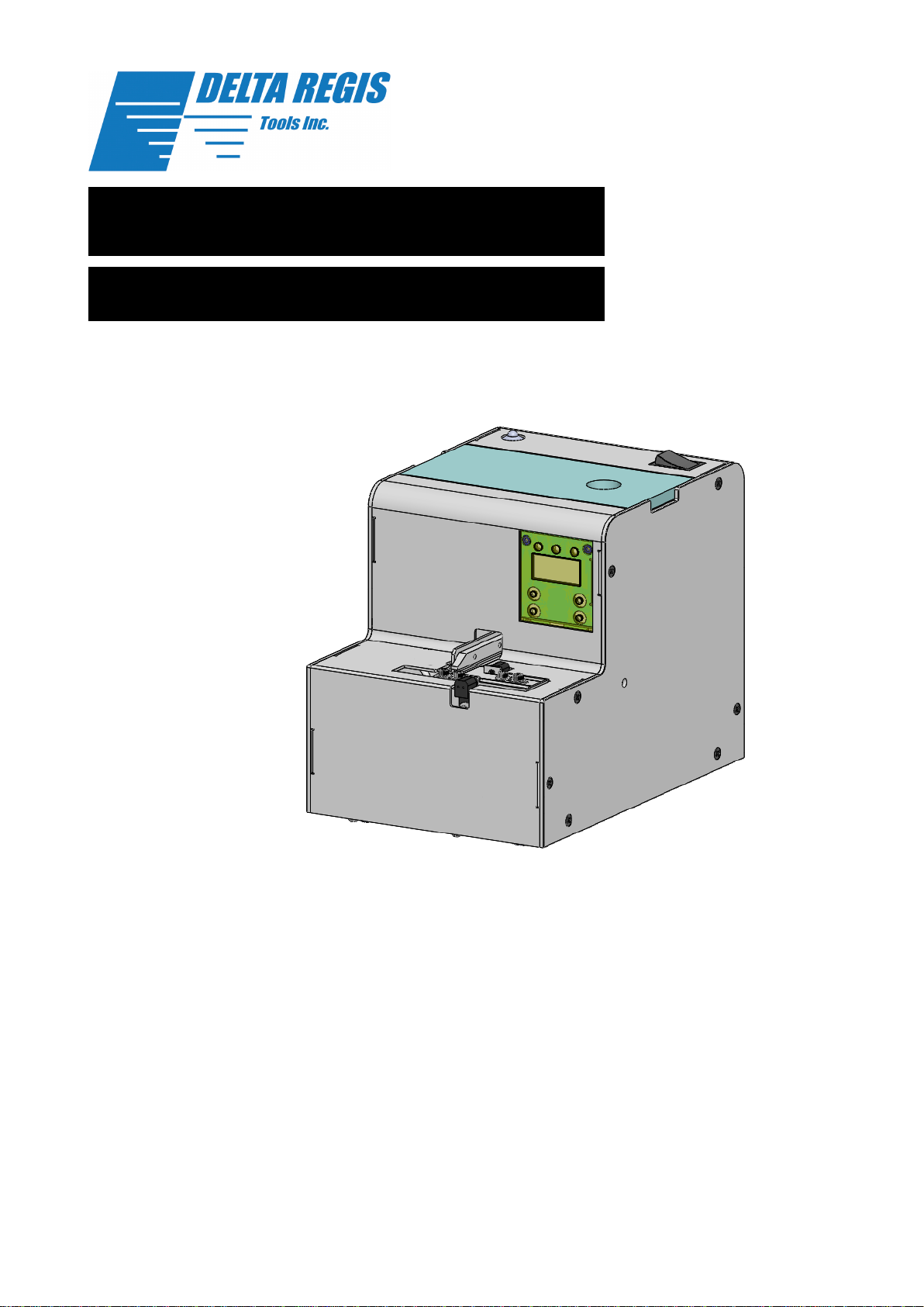
Description of Machine & PCB Function and Panel Hole Locations ...........................................2
Adjustment .........................................................................................................................................3
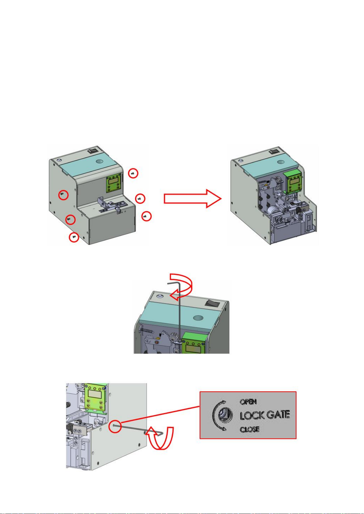
Track Adjustment.........................................................................................................................3
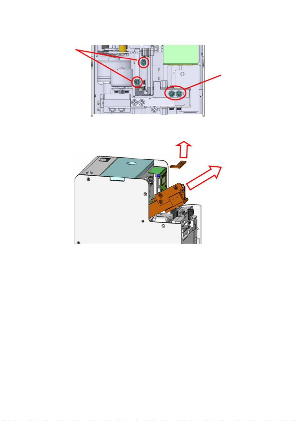
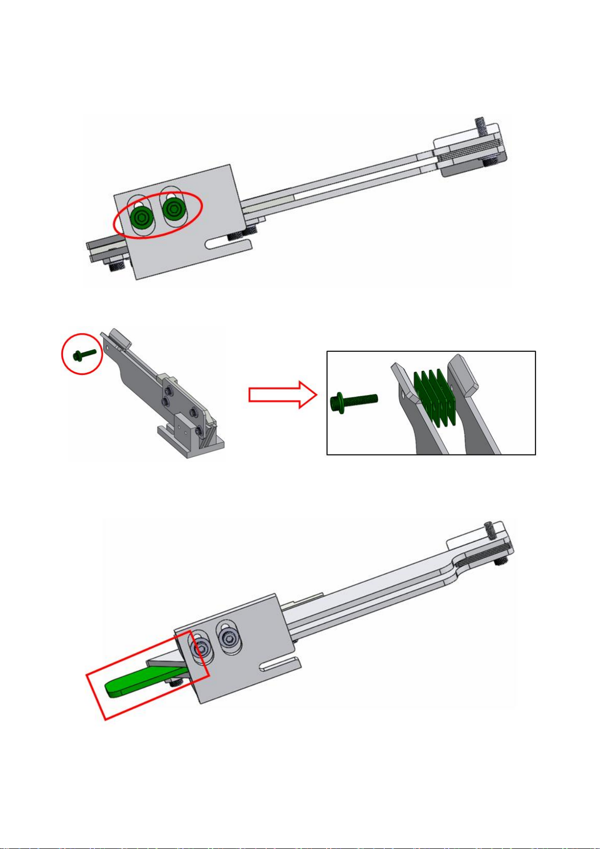
Track Removal.....................................................................................................................3
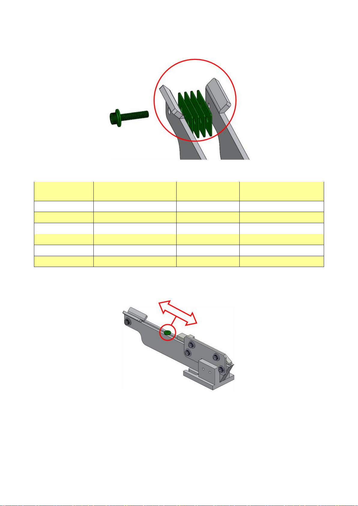
Adjust Track Width..............................................................................................................5
Track Installation .................................................................................................................7
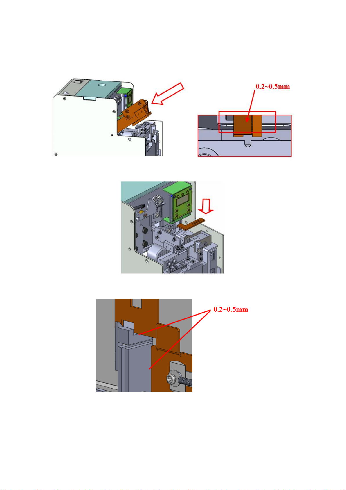
Adjustment of Keep Board ..........................................................................................................8
Adjustment of Infrared Device ....................................................................................................9
Adjustment of Dispensing Mechanism......................................................................................10
Adjustment of Container Funnel Inside Cylinder......................................................................13
Adjustment of Brush..................................................................................................................14
Method of Use...................................................................................................................................16
Quantity of Screws Placed In.....................................................................................................16
Signal Board Connection...........................................................................................................17
Counter Interface Operation.......................................................................................................18
Common Malfunction and Simple Resolution ..............................................................................21
Maintenance and Cleaning..............................................................................................................22
Warranty Clause..............................................................................................................................23

1
Check before Use
Equipped Accessories
Before the use of the Automatic Screw Feeder, please carefully check whether the following
accessories are complete:
Hex-key wrench 2.0*107mm (L type) *1
Voltage stabilizing transformer
AC 100~240V/DC12V*1
Rear specification sheet for sliding track rear
20*10*0.2mm*2pcs&0.5mm*6pcs
Operation manual *1
Jig plates, 1pcs each for 0.8/1.0/1.2/1.5/2.0
Check Screw Dimension
Before the use of the Automatic Screw Feeder, please check the dimension of the screw used, and
use the Vernier Caliper to perform measurements according to the following drawings:
Table a
a
Screw head width
b
Screw head thickness
c
Screw length
d
Screw diameter
e
Screw total length

2
Description of Machine & PCB Function and Panel Hole Locations
A.
LOCK GATE
Gate adjustment hole
B.
POWER
Power switch
C.
INDICATION
LED signal indicator
D.
DC POWER
DC power input hole
E.
GROUNDING
Grounding hole
F.
SIGNALWIRE
Signal cable

3
Adjustment
After checking the dimension of the screw used, before the use of the machine for the first time,
adjust relevant parts according to the screw dimension.
Track Adjustment
Track Removal
1. Remove the fixation screws (6 pcs) at the front cover of the housing, and remove the front cover
of the housing.
2. Face the machine, and use the equipped hex-key wrench to open the upper gate opening.
3. Face the machine, and use the equipped hex-key wrench to open the right gate opening.

4
4. Remove the horizontal conveying device board 4 and track fixation screws.
5. Remove the track.
Track fixation
screws
Horizontal
conveying device
board screw

5
Adjust Track Width
1. Unfasten the two fixation screws at the bottom of the track.
2. Remove the screws at the rear of the track, and remove the jig plate.
3. Install the jig plate at the front of the track, and adjust the clearance between the left and right
tracks, then fasten the screws in Step 1.

6
4. Remove the equipped jig plate, and place it at the rear of the track after assembly according to
Table b, then fasten the screws removed in Step 2.
※The assembly method is provided for reference only ※Table b
Screw dimension
(mm)
Sheet of thickness at the
rear of track (mm)
Screw dimension
(mm)
Sheet of thickness at the
rear of track (mm)
1.0
0.5 * 2 + 0.2 = 1.2
2.6
0.2 + 0.5 * 5 = 2.7
1.2
0.5 * 2 + 0.2 * 2 = 1.4
3.0
0.2 + 0.5 * 6 = 3.2
1.4
0.5 * 3 = 1.5
3.5
0.2 + 0.5 * 7 = 3.7
1.7
0.2 * 2 + 0.5 * 3 = 1.9
4.0
0.2 + 0.5 * 8 = 4.2
2.0
0.2 + 0.5 * 4 = 2.2
5.0
0.2 + 0.5 * 10 = 5.2
2.3
0.2 * 2 + 0.5 * 4 = 2.4
5. After adjustment is complete, take a screw and place on the track, followed by sliding it from
the rear toward the front. It is acceptable if the screw is able to slide smoothly.
Notes
a. Please ensure the middle of the tracks is flat and parallel, and adjustment to narrow front with
wide rear or vice versa is prohibited.
b. If it is a screw of 1 = 1 or 1 < 1, then it shall be adjusted to narrow front and wide rear, and the
dimension of the wide rear shall be greater than the total length of the screw.
c. During the adjustment of the clearance at the front of the tracks, the screws in Step 1 shall be
fastened flatly.

7
Track Installation
1. Install the adjusted track on the horizontal conveying vibration motor seat, and adjust the
distance; the distance away from the opening of the flat conveying device board is
approximately 0.2 ~ 0.5mm. Then, fasten the fixation screws.
2. Install the horizontal conveying device board 4, and fasten the screws.
3. Adjust the upper and right gates at a distance of approximately 0.2 ~ 0.5mm from the track.
Notes
a. During the installation the track, a clearance of 0.2 ~ 0.5mm shall be kept from the horizontal
conveying device board (opening) such that no contact shall be formed therebetween.
b. If the track cannot be installed successfully, please check whether the container funnel is
installed at an overly low position.
c. The upper and right gates shall be kept at a clearance of 0.2 ~ 0.5mm from the track.

8
Adjustment of Keep Board
1. Unfasten the screws on the horizontal conveying keep board for securing the keep board.
2. Use the jig plate to adjust the height of the keep board, and fasten the screws in Step 1.
Notes
a. During the adjustment of the keep board, the screws in Step 1 shall be fastened flatly in order to
prevent loose of screws during the use thereof.

9
Adjustment of Infrared Device
1. Unfasten the SENSOR (reception) securement base screws.
2. Adjust the infrared hole position (reception) to expose half of the hole, and then fasten the
screws in Step 1.
Notes
a. Please make sure that half of the SENSOR (reception) hole position is exposed; in case where
screws cannot be detected, then appropriate adjustment can be made.

10
Adjustment of Dispensing Mechanism
1. Adjust the dispensing mechanism toward the left to be at a minimum clearance with the base
plate, and ensure that the front end of the dispensing mechanism is parallel with the front end of
the base plate.
2. Unfasten the fixation screws on the horizontal conveying device board (opening).
3. Align the horizontal conveying plate opening with the track center, and ensure the sliding track
slides to the leftmost end at this time; then, fasten the screws unfastened in Step 2.
Parallel

11
4. Unfasten the screws of the securement plate of the horizontal conveying device board (opening),
and adjust the opening to be basically parallel with the front end of the track; it is prohibited to
be higher than the plane at the front of the track.
5. Unfasten the infrared securement base screws, adjust the base height such that it is just in
contact with the horizontal conveying device board (opening).
6. Slide left and right, it is acceptable as long as the sliding track slides smoothly.
Parallel
Just in
contact

12
7. Unfasten the sliding track limiter screws, adjust the horizontal conveying device such that the
opening stops at the infrared projection center, and then fasten the screws.
Notes
a. The horizontal conveying board (opening) shall be aligned with the track center, and the top
plane shall not be higher than the top plane of the front end of the track.
b. The completely adjusted track shall slide smoothly.
c. When the sliding track slides to the rightmost end, the horizontal conveying device (opening)
shall be aligned with the SENSOR infrared projection center.

13
Adjustment of Container Funnel Inside Cylinder
The container funnel is located at the track rear and fastened onto the cylinder vertical wall, which
is used for receiving screws falling from the cylinder and guiding such screws onto the track.
1. Use the equipped hex-key wrench to unfasten the hex-key screws at the rear of the machine.
2. Adjust the V shape of the container funnel to align with the track center, and the distance
between the container funnel and the track shall be approximately 0.8 ~ 1.0mm.
Notes
a. The container funnel shall be kept at a clearance of 0.8~1.0mm from the track rear and shall be
aligned with the track center.

14
Adjustment of Brush
1. Adjust the brush to the level position, and unfasten the brush securement board screws.
2. Place 5 ~ 8 screws inside the track at the rear of the keep board and adjust to the gate opening,
unfasten the brush fixation screws, and manually adjust the brush such that during the rotation
of the brush, the brush end just contacts with the screw heads. Fasten the screws in Step 1.
3. Adjust the front/rear position of the brush to the middle, and it is acceptable as long as the front
and rear are not in contact with others.

15
4. The brush securement board and the brush driving shaft shall be parallel and shall be at the
center location.
Notes
a. After the height adjustment of the brush is complete, manually rotate the brush again in order to
ensure that it is able to operation properly.
b. If there is difference between the brush lengths at the front and rear (long at the front and short
at the rear), then during the replacement of the brush, please ensure that it matches with the
track.

16
Method of Use
Quantity of Screws Placed In
Before placing the screws, the power shall be switched off first. Remove the feeding tank top cover,
check whether there is any foreign object in the screws placed in, and place the screws into the
feeding tank. The screws are added onto the two left and right sides equally to location at
approximately 1 ~ 2mm from the lower edge of the track in front of the gate opening.
The quantity of screws is approximately 200 ~ 220cc in principle. Objects other than the screws
used this time are foreign objects, which shall be removed first in order to prevent impacts on the
normal function of the machine.
Screws of size ≤10mm
Screws of size ≤15mm
Screws of size ≤19mm

17
Signal Board Connection
Connect PLC signal input
Connect PLC positive power
Signal board wiring diagram
1 of mainboard
CN5
In2 of sign
connection board J1
GND of
mainboard CN5
GND of sign
connection board
J1
Black
Red
Table of contents
Other Delta Regis Industrial Equipment manuals