Delta Separations CUP 15 Series Service manual

CUP 15
OPERATING AND SERVICE MANUAL

2
Copyright © 2018 by Delta Separations LLC®
All rights reserved. No portion of this book may be reproduced in any form without
permission from Delta Separations, except as permitted by U.S. copyright law.
For permission contact: sales@deltaseparations.com
Printed in the United States of America
System GEN 2.0; Manual V2, May 2018

3
Table of Contents
1. Safety................................................................................................5
Safety Notices................................................................................................................5
Ethyl Alcohol Safety Information.....................................................................................6
2. Basic Operation.................................................................................9
System Introduction .......................................................................................................9
Functional Overview.......................................................................................................9
3. Technical Specifications.................................................................. 11
Physical Characteristics...............................................................................................12
4. Installation and Setup...................................................................... 13
Lifting and Transport ....................................................................................................13
Unpacking the Crate.....................................................................................................13
Manufacturer-Provided Items.......................................................................................13
System Placement .......................................................................................................13
Power Requirements....................................................................................................14
Environmental Safety...................................................................................................15
Fire Suppression.......................................................................................................15
Lighting .....................................................................................................................15
Ventilation .................................................................................................................15
Ignition Prevention.....................................................................................................15
Static Control.............................................................................................................16
Placement and Types of Electrical Equipment...........................................................16
Gas Detection and Monitoring...................................................................................16
Preparing the CUP 15 for Operation.............................................................................16
Safety Check Prior to Operation...................................................................................16
Precautions and Limitation of Use................................................................................17
5. Control Panel Overview................................................................... 18
Operator Control Panel ................................................................................................19
Operator Control Panel Display....................................................................................19
Program Cycles............................................................................................................19
RPM Control.................................................................................................................21
Changing Parameters ..................................................................................................22
Main Control Panel.......................................................................................................24

4
6. Basic Extraction Process................................................................. 25
Before Extracting..........................................................................................................25
Extraction Overview .....................................................................................................25
Powering Up the System..............................................................................................26
Chilling the Alcohol (Optional)......................................................................................26
Preparing the Material..................................................................................................27
Loading the Filter Bag..................................................................................................27
Loading the System Basket..........................................................................................27
Filling the Chamber with Alcohol ..................................................................................28
Recommendations for Nitrogen-Assisted Filling ...........................................................29
Running the Agitation Wash Cycle (Preferred Method).................................................33
Draining the System.....................................................................................................33
Running the Spin Dry Cycle .........................................................................................33
Cleaning the System....................................................................................................34
7. System Maintenance & Support...................................................... 35
Flushing the Oiler.........................................................................................................36
8. Troubleshooting .............................................................................. 37

5
1.
Safety
Please read and follow all safety and use instructions.
ONLY TRAINED PROFESSIONALS WITH A COMPLETE OPERATIONAL UNDERSTANDING OF
THE EQUIPMENT—AND A FULL UNDERSTANDING OF THE RISKS ASSOCIATED WITH
ALCOHOL USE—SHOULD BE AUTHORIZED TO USE THE EQUIPMENT. THE USE OF
ALCOHOL HAS RISKS. ANY MISUSE OF THIS EQUIPMENT CAN RESULT IN SEVERE INJURY,
INCLUDING BUT NOT LIMITED TO DEATH, DISABILITY AND PROPERTY DAMAGE.
Safety Notices
CAUTION
WARNING
DANGER
A CAUTION notice indicates a potentially hazardous situation which,
if not avoided, may result in minor or moderate injury, or damage to
the equipment. Do not proceed beyond a CAUTION notice until the
indicated conditions are fully understood and met.
A WARNING notice indicates a hazardous situation which, if not
avoided, could result in death or serious injury.
A DANGER notice indicates an immediate hazard which, if not
avoided, will result in death or serious injury.
IT IS THE OPERATOR’S SOLE RESPONSIBILITY TO USE EQUIPMENT IN A SAFE MANNER.
OPERATOR ASSUMES ALL RISK ASSOCIATED WITH THE USE OF THIS EQUIPMENT AND
AGREES THE EQUIPMENT IS ONLY TO BE UTILIZED FOR LAWFUL PURPOSES.

6
Ethyl Alcohol Safety Information
Emergency Overview
OSHA Vacated PELs: Alcohol: 1000 ppm TWA; 1900 mg/m3 TWA
Personal Protective Equipment
Eyes: Wear appropriate protective eyeglasses or chemical safety goggles as described by
OSHA's eye and face protection regulations in 29 CFR 1910.133 or European Standard
EN166.
Skin: Wear appropriate protective gloves to prevent skin exposure.
Clothing: Wear appropriate protective clothing to prevent skin exposure.
Respirators: A respiratory protection program that meets OSHA's 29 CFR 1910.134 and
ANSI Z88.2 requirements or European Standard EN 149 must be followed whenever
workplace conditions warrant a respirator's use.
First Aid Measures
Eyes: Get medical aid. Gently lift eyelids and flush continuously with water for at least 15
minutes.
Skin: Get medical aid. Wash clothing before reuse. Flush skin with plenty of soap and
water.
Ingestion: Do not induce vomiting. If victim is conscious and alert, give 2-4 cups of milk or
water. Never give anything by mouth to an unconscious person. Get medical aid.
Inhalation: Remove from exposure and move to fresh air immediately. If not breathing,
give artificial respiration. If breathing is difficult, give oxygen. Get medical aid. Do NOT use
mouth-to-mouth resuscitation.
General Information: Containers can build up pressure if exposed to heat and/or fire. As in
any fire, wear a self-contained breathing apparatus in pressure-demand, MSHA/NIOSH
(approved or equivalent), and full protective gear. Vapors may form an explosive mixture
with air. Vapors can travel to a source of ignition and flash back. Vapors will burn if involved
in a fire. Flammable liquid can release vapors that form explosive mixtures at temperatures
above the flashpoint. Use water spray to keep fire-exposed containers cool. Containers
may explode in the heat of a fire.
Extinguishing Media: For small fires, use dry chemical, carbon dioxide, water spray or
alcohol-resistant foam. For large fires, use water spray, fog, or alcohol-resistant foam. Use
water spray to cool fire-exposed containers. Water may be ineffective. Do NOT use straight
streams of water.
Flash Point: 16.6° C (61.88° F)
Auto-ignition Temperature: 363° C (685.40°F)
Explosion Limits, Lower: 3.3 vol %
Explosion Limits, Upper: 19.0 vol %
NFPA Rating: (estimated) Health: 2; Flammability: 3; Instability: 0

7
DANGER
DANGER
WARNING
WARNING
WARNING
WARNING
WARNING
WARNING
CAUTION
CAUTION
CAUTION
CAUTION
CAUTION
This equipment uses high-proof alcohol. Alcohol is a flammable liquid.
Improper use may cause alcohol to discharge, resulting in an unsafe
work environment. Use a properly-rated CFM fume hood, personal
protective equipment (PPE), and appropriate detectors as required.
Inhalation of high concentrations of Alcohol vapor may affect the central
nervous system. This is characterized by nausea, headache, dizziness,
unconsciousness and coma. It may cause respiratory tract irritation. In
high concentrations, it may cause narcotic effects. Please read the thyl
Alcohol Safety Information Sheet for further safety information.
Operator must follow all precautions and safety guidelines to ensure their
own safety, the safety of other personnel, and the protection of property.
Always visually monitor fill levels, tanks, valves, and hoses for leakage.
While the system is protected with pressure relief valves, care should be
taken to ensure overfilling does not occur.
All hoses may contain alcohol under slight pressure. Wear proper
personal protective equipment (PPE) such as safety goggles and gloves
when disconnecting hoses and working aroundalcohol.
Imbalance of the basket may cause major damage to the bearing and
shaft assembly and put the operator at risk. Proper bag loading is
critical. The improper use of the CUP or unapproved modifications
may result in serious injury.
Before opening the lid manually, be sure that the basket has
completely stopped spinning.
Component wear varies depending on the amount of usage. Inspect
all nuts, bolts, and gaskets before each use. If there is any question
about the integrity of a component, replace it immediately.
Make certain all safety devices are functioning properly before
operating the equipment.
The alcohol detector must be used always in and around the
extraction zone.
Never apply pressure or vacuum to the system chamber.
Never apply more than 10 psi and 15 mmHg to the system jacket.
It is important to have the manual relief valve open during filling to
allow the displacement of the head pressure.

8
CAUTION
CAUTION
CAUTION
CAUTION
CAUTION
CAUTION
The facility must provide adequate ventilation/exhaust, as determined
by the Engineer of Record, to maintain the local atmosphere below
25% of the Lower Flammability Limit (LFL).
Alcohol vapor is heavier than air and can settle in low places.
DO NOT use or store equipment or containers where they could be
exposed to high temperatures. Relief valves can open allowing
alcohol to escape. DO NOT artificially heat equipment or containers
above 125°F.
This system is NOT equipped with an overfill prevention device.
Ensure proper fill levels prior to operation.
All system containers must be checked for accidental pressurization.
Depressurize prior to opening.
DO NOT allow children to tamper with or play near the equipment.

9
2.
Basic Operation
System Introduction
The CUP 15-Series Alcohol Extraction System provides the ability to extract targeted
botanical compounds from a diverse plant species. This unique separation technology
combines closed-loop alcohol extraction with mechanical centrifugation, ensuring high-
purity extractions. The system isolates specific compounds by controlling key
process variables, including solvent residence times, rpm control, agitation force, and
temperature.
Functional Overview
The process below is illustrated in Figure 2-1.
1. The CUP 15 is loaded with a predetermined amount of plant material.
2. Alcohol is pushed out of the source keg (1) using compressed nitrogen (with regulator)
(1A) into the CUP chamber (3).
3. Secondary Option (not shown) Alcohol is transferred out of the source keg (1) using a
pneumatic transfer pump powered by either a remote air compressor or inert
compressed gas.
4. The CUP chamber (3) is filled with alcohol to operator specifications.
5. The plant material/alcohol then undergo a bi-directional agitation aimed at removing the
target compounds.
6. When agitation is complete, the discharge valve (5) is opened, and the tincture is
diverted to a bulk crude reservoir (7) for future processing.
7. The spent plant solids are spun dry using centripetal force to remove 98% of the
remaining alcohol tincture trapped within the plant material.
8. The system is then opened and unloaded by retrieving the filter bag from the basket.
9. The process can be repeated until desired saturation levels have been achieved.
This method provides the safest, most economically efficient way to batch-process biomass
using alcohol.

10
Figure 2-1. Process Flow Diagram

11
3.
TechnicalSpecifications
Table 3-1 shows the specifications for the CUP 15.
CAUTION
CAUTION
CAUTION
Never apply pressure or vacuum to the system chamber.
Never apply more than 10 psi and 15 mmHg to the system jacket.
The facility must provide adequate ventilation/exhaust, as determined
by the Engineer of Record, to maintain the local atmosphere below
25% of the Lower Flammability Limit (LFL).
Table 3-1. Technical Specifications
CUP 15 Technical Specifications
Maximum speed
1800 rpm
Basket capacity
12lbs. to 15 lbs. (depending on mill size)
Maximum temp
60° C
Minimum temp
-40° C
Maximum pressure
5 psi (Not recommended)
Vacuum
Not recommended
Control system
SIEMENS Programmable Logic Control
Speed set range
50-1800 rpm
Speed set step
10 rpm
Timer set range
1-15 minutes and hold position
Timer set step
1 minute
Motor
2HP / 3HP motor explosion-proof hazloc C1D2
Supply Values
230V, 50Hz / 60 Hz, single phase
Power Consumption
2500W
12
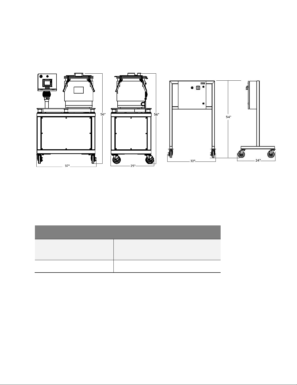
Physical Characteristics
Figure 3-1 and Table 3-2 show the physical characteristics of the CUP 15.
Figure 3-1. CUP 15 Physical Characteristics
Width = 37 inches
Depth = 25 inches
Height = 56 inches
Width = 32 inches
Depth = 24 inches
Height = 54 inches
Table 3-2. Physical Characteristics
CUP 15 Physical Characteristics
System External Dimensions
(W x D x H) inches
CUP 15 Footprint: 37” W x 25” D x 56” H
Drive Panel Footprint: 32” W x 24” D x 54” H
Net / Packed weight (kg)
1095 Lbs. / 497 kg

13
4.
Installation andSetup
Lifting and Transport
All lifting and transport must be done using proper handling equipment. The system must
always remain in a vertical upright position and never leaned or turned over on its side.
Unpacking the Crate
Remove the packing cardboard box and the second nylon packing around the centrifuge.
Manufacturer-Provided Items
Items provided with the system are listed below. Please ensure everything is included and
intact.
−Main Control Panel
−CUP System
−Mesh Bags
−Lid Assembly Fittings
−Drain Port Assembly Fittings
−(2) Distillery Hoses and fittings. One long Hose (Fill Hose) and One Short Hose (Drain
Hose)
−System Parts Components and Packing List
−System Manual
System Placement
Prior to installing the system:
−Check that no damage to the system or casters has occurred during transport.
−Check that the system placement area is level and suitable for positioning. Double-
check that all four casters are on level ground.
−Leave sufficient space around the system for an unobstructed work area.
−Verify that the system is placed in a properly ventilated area that has been approved by
your local fire marshal.

14
Figure 4-1. CUP 15 GroundingReceptacles
Power Requirements
The CUP 15 requires a dedicated 230V, 50Hz / 60 Hz, 30 amp circuit. Please ensure
that all receptacles (NEMA L6-30R) match the required power ratings (see Figure
4-1).
NOTE: Always plug the system into correctly grounded receptacles.
Figure 4-2 shows properly wired grounding straps and their placement.
NOTE: Grounding straps should be wired by a licensed electrician.
Figure 4-2. System Grounding Straps

15
Environmental Safety
This section includes safety recommendations that apply specifically to the CUP 15 system.
Verify that the area is set up properly before installing the system.
The CUP 15 has been designed to operate safely under the following environmental
conditions:
−Indoor use only
−Maximum relative humidity of 75%
−Ambient temperatures of 5°C to 32°C
Fire Suppression
Install an automatic fire suppression system with 155° auto discharge heads, according to
Local and State building codes. The manual release handle should be accessible outside
the containment area, and accessible when the extraction area is closed. Install two Alcohol
detectors in the work area. Place a 10 lb. manual fire extinguisher with appropriate ratings
within the extraction area.
Lighting
Area should be well lit with a properly rated configuration. Clearly mark exits with a lighted
sign and install emergency lights/battery backup in case of any power failures.
Ventilation
The ventilation system’s purpose is to keep accidental liquid and vapor release
concentrations low enough to prevent ignition. The exhaust ventilation system should
comply with AHJ requirements and should be capable of capturing any solvent vapors, if
released.
Fans must be able to extract enough air to match the vapors of a spill ½ the normal working
volume (simulating a failure in either the recovery or source container of most of the
systems in use, including rotary evaporators, Buchner funnels, etc.) for double the amount
of time it would take a worker to safely contain the spill using appropriate tools and
procedures.
Sanitary areas should be fitted with properly rated HEPA HVAC fan and filter equipment to
control contaminants.
Ignition Prevention
No open flame devices will be allowed in the fume hood area. Smoking is not permitted in
the work area and ‘No Smoking’ signs should be posted.
No appliances with pilot lights are permitted.
No appliances with the possibility of creating open sparks (i.e., open contacts/relays on
most refrigerators, chillers, etc.) are permitted.
No handheld electrical tools may be operated during extraction operations.

16
Static Control
To reduce the possibility of static electricity sparks, antistatic mats can be placed around
extraction and distillation equipment. Equipment will be grounded using grounding straps
provided and shall conform to NEC/NFPA guidelines to help prevent static electricity and
discharges.
Placement and Types of Electrical Equipment
When possible, locate all electrical outlets, switches, light fixtures, electric appliances and
equipment outside the extraction equipment area. All devices should be wired according to
NEC & local AHJ.
Use low voltage circuits inside the containment area to help prevent sparks from high
voltage devices.
Gas Detection and Monitoring
Since the proposed extraction process utilizes alcohol for solvent extraction, presence of
alcohol vapor will be monitored in the work area. Monitoring systems will provide readout
and/or a signal that indicates that dangerous levels of flammable vapor have been reached.
An additional fixed monitor will be placed in the inlet of the exhaust air fan to monitor
alcohol vapor evacuation. Gas detection devices will be calibrated on a weeklyinterval.
Preparing the CUP 15 for Operation
The CUP arrives factory-tested and inspected for liquid leaks and manufacturing flaws.
However, shipping and/or frequent moving of the system can loosen components. It is the
operator's responsibility to check for leaks and damage prior to operation. It is advised to
perform a ‘liquid run’ check with alcohol (no material) in order to clean the system while
inspecting for leaks.
CAUTION Operator must learn and become familiar with all procedural
operations and liquid transfer mechanics prior to use (e.g., system
flow diagram, plumbing schematic, liquid transfer operations, and/or
pneumatic pump assembly).
Safety Check Prior to Operation
Before using the system, perform the following system inspection.
1. Open the lid and visually inspect the system, basket assembly and lid seal for
cleanliness and wear and tear. Check the inner basket bolts with a torque wrench using
25 foot-pounds.
2. Confirm the main system panel is plugged into a correctly rated 230V / 30amp
receptacle NEMA L6-30R 250V.
3. Make sure the grounding straps have been installed correctly and electricallytested
using a technician’s meter.
4. Check for any blockages within the hoses, quick-connect fittings, inlet valves, and drain
assembly.
5. Inspect all tanks, fittings and seals for damage orleaks.

17
6. Make sure all alcohol detectors are functioning properly and ready for use.
7. Make sure all pressure devices are set to correct parameters.
8. Make sure the ventilation / fume hood is turnedon.
Once the system has been cleaned, inspected, and the operator is familiar with the liquid
transfer process, the operator may proceed to extract in the CUP.
Precautions and Limitation of Use
Please pay special attention to the following:
−Never attempt to open the lid while the basket is spinning.
−Make sure the system placement is on flat, level ground.
−Always power OFF the main panel when not in use for longer than 60 minutes.
−Never overload the system or use the system without a balanced load.
−Ensure proper material loading and balancing of filter bags.
−Only use the system as described in this manual.

18
5. Control PanelOverview
There are two control panels provided as part of the CUP 15. The Operator Control Panel
is mounted on the same frame as the centrifuge platform and is used for direct operation of
the equipment within the extraction zone. The Main Control Panel is mounted on a
separate modular frame that is tethered outside the extraction zone. Both panels have been
designed and built in accordance with Class 1 Div 2 standards, with Operator Panel UL
certified for use within C1D2 hazardous locations. See Figure 5-1.
Figure 5-1. Control Panels
NOTE: Make sure the Main Control Panel is located outside of the extraction zone. The
system Operator Panel is attached to the mainframe of the system and is rated for use
within C1D2 environments. The Main Control Panel is located outside of the C1D2 HAZ
zone. There is 20 ft of cord tethering the main drive panel to the system.

19
Operator Control Panel
The Operator Control Panel consists of an HMI (Human Machine Interface), Emergency
Stop Button (In the OUT position) and the HazLoc name plate. See Figure 5-2.
Figure 5-2. Operator Control Panel
Operator Control Panel Display
The Operator Control Panel is mounted to the system motor. This is the touchscreen HMI
(Human Machine Interface) for operational control. See Figure 5-3.
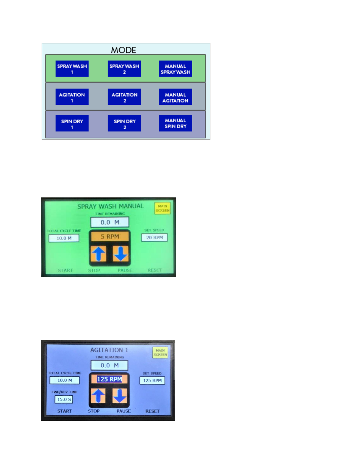
Program Cycles
The CUP 15 offers 3 Program Modes:
−Spray Wash (Currently Not Used)
−Agitation Wash
−Spin Dry modes
Each Program Mode has two programmable auto-profiles and one programmable
Manual profile.
NOTE: The auto profiles (1 & 2) automatically update the last user parameters entered.
The manually-entered profile will reset to the factory default after every use.
20
Figure 5-3. Operator Control Panel Display
Spray Wash Cycle (Currently Not Used)
The Spray Wash Cycle (Figure 5-4) is selected on the HMI where the Cycle Time and RPM
Set Speed are configured to operator specifications. Push START to run the cycle.
Figure 5-4. Spray Wash Cycle
Agitation Wash Cycle
The Agitation Wash Cycle (Figure 5-5) is selected on the HMI where the Cycle Times and
Set Speeds are configured to the operator specifications. Push START to run the cycle.
Figure 5-5. Agitation Wash Cycle
Table of contents
Popular Laboratory Equipment manuals by other brands


Agilent Technologies
Agilent Technologies 850-DS Operator's manual

PerkinElmer
PerkinElmer VesselVue quick start guide

PerkinElmer
PerkinElmer RamanMicro 200 Series Getting started guide

Asahi KASEI
Asahi KASEI IBD 1K user manual

Star Lab
Star Lab N2400-0001 Vortex IR instruction manual

J.P. SELECTA
J.P. SELECTA APL-54 manual