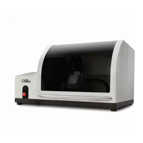
Merck Millipore CellASIC ONIX2 User manual

User Guide
www.sigmaaldrich.com
CellASIC®ONIX2
Microfluidic System
Cat. No. CAX2-S0000
The life science business of
Merck operates as MilliporeSigma in
the US and Canada.

Notice
We provide information and advice to our customers on application technologies
and regulatory matters to the best of our knowledge and ability, but without
obligation or liability. Existing laws and regulations are to be observed in all cases
by our customers. This also applies in respect to any rights of third parties. Our
information and advice do not relieve our customers of their own responsibility
for checking the suitability of our products for the envisaged purpose.
The information in this document is subject to change without notice and should
not be construed as a commitment by the manufacturing or selling entity, or
an affiliate. We assume no responsibility for any errors that may appear in this
document.
Contact Information
For the location of the office nearest you, go to www.sigmaaldrich.com/offices.
Technical Assistance
Visit the tech service page on our web site at www.sigmaaldrich.com/techservice.
Standard Warranty
The applicable warranty for the products listed in this publication may be found
at www.sigmaaldrich.com/terms.
For research use only. Not for use in diagnostic procedures.
C
Made in U.S.A.
EMD Millipore Corporation,
Burlington, MA, USA, an affiliate of
Merck KGaA, Darmstadt, Germany
Millipore, Sigma-Aldrich, CellASIC, and Millex are trademarks of Merck KGaA,
Darmstadt, Germany or its affiliates. Detailed information on trademarks is available via publicly accessible resources.
© 2019 Merck KGaA, Darmstadt, Germany and/or its affiliates. All Rights Reserved.
20202092, Rev. 04/19

Contents
1 Introduction to the CellASIC®ONIX2 Microfluidic System .................................... 1
1.1 Overview...................................................................................................... 1
1.2 Benets ....................................................................................................... 1
1.3 Environmental Control.................................................................................... 2
1.4 Applications .................................................................................................. 3
1.5 CellASIC® ONIX Microuidic Plate and Cell Type Compatibility .............................. 3
1.6 Product Use Limitations .................................................................................. 3
2 Components Required ......................................................................................... 4
3 Symbols Used in this User Guide /
Symboles utilisés dans ce manuel d’utilisation..................................................... 5
4 Product Labeling ................................................................................................. 6
5 Safety Precautions / Précautions de sécurité ....................................................... 6
6 Installation and Setup......................................................................................... 8
6.1 Packaging..................................................................................................... 8
6.2 Site Requirements ......................................................................................... 8
6.3 CellASIC®ONIX2 Software Installation ............................................................. 9
6.4 CellASIC® ONIX2 Microuidic System Setup ...................................................... 9
7 CellASIC®ONIX2 Software Features ...................................................................13
7.1 Opening Screen............................................................................................13
7.2 Manual Mode Tab..........................................................................................14
7.3 Plate Layout Tab...........................................................................................18
7.4 Protocol Editor Tab........................................................................................20
7.5 Run Tab ......................................................................................................24
7.6 Status Bar ...................................................................................................26
7.7 Menu Items and Advanced Features ................................................................28
8 Operation...........................................................................................................37
8.1 Before Your Experiment.................................................................................37
8.2 Creating and Running a New Experiment .........................................................38
8.3 Repeating a Previous Experiment with Minimal Clicks ........................................45
8.4 Using the Mini-view ......................................................................................46
8.5 Viewing and Exporting Data from a Previously Run Experiment...........................48

9 Maintenance and Cleaning..................................................................................50
9.1 Running a System Self Check.........................................................................50
9.2 Cleaning the CellASIC® ONIX2 Microuidic System ............................................51
9.3 Cleaning the Gasket......................................................................................51
9.4 Gasket/Manifold Assembly .............................................................................51
9.5 Cleaning the Manifold and Tubing....................................................................52
9.6 Replacing Manifold Luer Filters .......................................................................54
10 Troubleshooting .................................................................................................55
11 Specifications.....................................................................................................58
12 Ordering Information .........................................................................................60
Contents (continued)

1 Introduction to the CellASIC®ONIX2
Microfluidic System
1.1 Overview
The CellASIC®ONIX2 Microfluidic System enables continuous live-cell imaging
with media flow, temperature control, and gas environment control. A selection of
proprietary microfluidic plate designs allows cells to be captured and exposed to
different conditions via flow channels.
The system can be used with typical inverted microscopes and the microfluidic
plates fit standard multiwell plate stage adapters. The CellASIC®ONIX2 Microfluidic
System connects to the microfluidic plate via a pneumatic manifold that uses
pressurized air to control flow within the plate. A vacuum seal created between
the manifold and the microfluidic plate ensures that each well is independent and
that flow rates and fluid switching are accurate. Flow and environment control are
managed through a computer software program.
This user guide covers the setup and operation of the CellASIC®ONIX2 Microfluidic
System. User guides for the CellASIC® ONIX Microfluidic Plates are available at
www.sigmaaldrich.com/cellasic.
CellASIC®ONIX2
Microfluidic System
To Microfluidic Plate
Seal Manifold
Ready Sealed Error
Figure 1. CellASIC®ONIX2 Microfluidic System setup
1.2 Benefits
●The CellASIC®ONIX2 Microfluidic System provides a total solution for controlling
the perfusion, temperature, and gas environment for time-lapse, live-cell
imaging applications.
●The CellASIC®ONIX2 Software automates the entire experiment, allowing
scheduled flow changes without supervision. Customized experiments can
be performed by programming changes to media solutions, flow rates, and
exposure times. The easy-to-use software is flexible and can generate simple
solution-switching protocols or advanced flow profiles.
●The precision laminar flow maintained by the system creates a highly stable
environment for cells. The CellASIC®ONIX2 Microfluidic System requires only
microliter volumes of fluid and can run for multiple days without refilling.
20202092 04/19 1 of 60 CellASIC®ONIX2 Microfluidic System

1.3 Environmental Control
The CellASIC®ONIX2 Microfluidic System can provide both temperature and
gas environment control. If you already have or do not require temperature
control, the CellASIC®ONIX2 Manifold Basic can be used to provide a defined gas
environment to the cell culture region. If temperature control is also desired, the
CellASIC®ONIX2 Manifold XT is the solution. The CellASIC®ONIX2 Manifold XT
takes advantage of the small size of the culture volume to efficiently, accurately,
and conveniently maintain a precise cell culture environment. Temperature control
is achieved using a convective heat exchange module where recirculating air gently
and uniformly warms or cools the cells.
NOTE: For immersion objectives and air objectives with a working distance less
than 2 mm, it is necessary to warm the objective using an objective heater (see
Installation and Setup).
Gas control is achieved using highly accurate external premixed gas sources.
The system purges the cell culture region at a gas consumption rate of only
5 mL/minute. Please contact your local sales representative for assistance in
selecting the ONIX2 platform components that will work best with your specific
microscopy setup and experiment.
Convective heat exchanger
Air pressure-driven flow
#1.5 thickness 170 µm thick glass
Cell culture chambers
Recirculating temperature-
controlled gas mixture
Manifold
Microfluidic plate
Figure 2. Manifold and plate cutaway
20202092 04/19 2 of 60 CellASIC®ONIX2 Microfluidic System

1.4 Applications
The CellASIC® ONIX2 Microfluidic System and Plates are perfect for many live cell
imaging applications. The following are some common applications:
● Long-term time-lapse imaging ●Kinetic responses to solution change
●Cell cycle analysis ●Apoptosis
● Protein localization ●Cell fixing and immunostaining
●Cell migration ●Mitosis
● GFP/CFP/YFP expression
1.5
CellASIC® ONIX Microfluidic Plate and Cell Type Compatibility
The CellASIC®ONIX2 Microfluidic System is compatible with all CellASIC®ONIX
Microfluidic Plates. Each unique plate design provides compatibility with a range of
cell sizes and types as follows:
● Y04 Series Microfluidic Plates are compatible with non-adherent cells that are
3.5–7 µm in diameter.
Examples: S. cerevisiae, S. pombe
● B04 Microfluidic Plates are compatible with non-adherent cells that are
0.7–4.5 µm in diameter.
Examples: E. coli, B. subtilis, cyanobacteria
● M04 Series Microfluidic Plates are compatible with any adherent or non-adherent
mammalian cell line capable of culture on glass.
Examples: MCF-7, HeLa, NIH3T3, PC3, primary cells, stem cells
For the most up-to-date list of our current plate types, please visit
www.sigmaaldrich.com/cellasic.
Please contact Technical Service for questions about cell types or coatings.
1.6 Product Use Limitations
The CellASIC®ONIX2 Microfluidic System is intended for research use only. It is not
for use in diagnostic procedures.
All due care and attention should be exercised in the handling of the CellASIC®
ONIX2 Microfluidic System and CellASIC®ONIX Microfluidic plates. Instructions
provided in this manual should be followed when using CellASIC®ONIX2 System.
If the equipment is used in a manner not specified by the manufacturer, protection
provided by the equipment may be impaired and the warranty may be voided.
20202092 04/19 3 of 60 CellASIC®ONIX2 Microfluidic System

2 Components Required
The following components are required for a functional CellASIC®ONIX2 System. Refer to
Ordering Information for additional manifolds, accessories, and other components.
Component Cat. No.
CellASIC®ONIX2 Microfluidic System
Includes ONIX2 Filter Multiconnector, Software USB Drive,
Replacement Filter Pack, Accessory Fittings, Self Check Plate,
Cleaning Plate.
CAX2-S0000
CellASIC®ONIX2 Manifold XT (Temperature Controlled)
OR
CellASIC®ONIX2 Manifold Basic (No Temperature Control)
CAX2-MXT20
CAX2-MBC20
CellASIC®ONIX Microfluidic Plates Refer to
Ordering Information
20202092 04/19 4 of 60 CellASIC®ONIX2 Microfluidic System

3 Symbols Used in this User Guide /
Symboles utilisés dans ce manuel d’utilisation
The following symbols are used throughout this user guide and/or on product labels, and
the user shall abide by indicated requirements:
Les symboles suivants sont utilisés tout au long de ce manuel d’utilisation et/ou sur les
étiquettes des produits ; l’utilisateur devra respecter les exigences indiquées :
Symbol /
Symbole Definition Définition
YCaution, consult accompanying
documents.
Attention, consultez les documents
joints.
CCE conformity marking. Reference
Declaration of Conformity for specific
directives.
Marquage de la conformité CE.
Déclaration de conformité à certaines
directives pour référence.
hCatalogue number Référence
NDate of manufacture Date de fabrication
MManufacturer Fabricant
fSerial number Numéro de série
iConsult instructions for use. Consultez le mode d’emploi.
Federal Communications Commission
(FCC) conformity marking
Marquage de la conformité avec
la Commission fédérale des
communications américaine
(FCC pour Federal Communications
Commission)
Canadian Standards Association®
(CSA) conformity marking
Marquage de la conformité avec
l’Association canadienne de
normalisation (CSA pour Canadian
Standards Association®)
Do not discard with common solid
waste at end of life. Segregate with
other waste electrical and electronic
equipment (WEEE) and send to an
appropriate facility for recycling.
For information on recycling
electrical and electronic products
in the European Union, please visit
www.sigmaaldrich.com/weee.
Ne pas jeter avec les déchets solides
communs en fin de vie. Mettre à part
avec les autres déchets d’équipements
électriques et électroniques (DEEE)
et envoyer à une entreprise habilitée
pour recyclage. Pour une information
sur le recyclage des produits
électriques et électroniques dans
l’Union européenne, veuillez consulter
la page www.sigmaaldrich.com/weee
sur Internet.
20202092 04/19 5 of 60 CellASIC®ONIX2 Microfluidic System

4 Product Labeling
Figure 3. Product label appears on back of the system
5 Safety Precautions / Précautions de sécurité
Review and understand the safety precautions below before installing and operating the
CellASIC®ONIX2 Microfluidic System.
Lire et comprendre les précautions de sécurité ci-dessous avant d’installer et de faire
fonctionner le Système de microfluidique CellASIC®ONIX2.
YWARNING YATTENTION
To avoid danger of electric shock, do
not install the system in an area with
a high humidity level. Refer to Site
Requirements in section 6.
Pour éviter le risque de choc électrique, ne
pas installer le système dans une zone où
le taux d’humidité est élevé. Se reporter au
paragraphe “Site Requirements” (Exigences
relatives au lieu d’installation) de la Section 6.
Do not touch the cables or power plugs
with wet hands.
Ne pas toucher les câbles ou les prises
électriques avec des mains mouillées.
To avoid potential shock hazard, use the
correct plug configuration and make sure
that the power cable is plugged securely
into a properly grounded AC power outlet.
Make sure that the connection between
the cable and the system is secure.
Pour éviter le risque potentiel de choc, utiliser
la bonne configuration de prise et s’assurer
que le câble électrique est solidement branché
dans une prise de courant correctement reliée
à la terre. S’assurer que la connexion entre le
câble et le système est sécurisée.
Always ensure that the power supply
input voltage matches the voltage
available in your location.
Toujours s’assurer que la tension du courant
d’alimentation du système correspond bien à
la tension disponible sur place.
Use only the power cables supplied by
EMD Millipore Corporation for use with
the CellASIC®ONIX2 Microfluidic System.
Use of other power cables may damage
the system.
Utiliser uniquement les câbles électriques
fournis par EMD Millipore Corporation
pour une utilisation avec le Système de
microfluidique CellASIC® ONIX2. L’utilisation
d’autres câbles électriques pourrait
endommager le système.
Minimize power draw from other
instruments on the same power circuit.
Minimiser la consommation de courant par
d’autres instruments branchés sur le même
circuit.
20202092 04/19 6 of 60 CellASIC®ONIX2 Microfluidic System

YWARNING YATTENTION
Do not use with flammable or explosive
liquids.
Ne pas utiliser avec des liquides inflammables
ou explosifs.
Before cleaning and moving the system,
always turn off power and unplug power
supply.
Avant de nettoyer ou de déplacer le système,
toujours l’éteindre et le débrancher.
When working with biological material,
always wear a suitable lab coat,
disposable gloves, and eye protection.
Proper lab safety should always be
followed when using the system.
Lorsque vous travaillez avec des matières
biologiques, toujours porter une blouse de
laboratoire, des gants à usage unique et une
protection oculaire adéquats. Il convient de
toujours suivre les mesures de sécurité au
laboratoire appropriées lors de l’utilisation du
système.
For all experiments, perform biosafety risk
assessment, mitigation, decontamination,
and waste disposal procedures in
accordance with established national and
institutional guidelines.
Pour toute expérience, effectuer les procédures
d’évaluation et de réduction des risques de
biosécurité, de décontamination et d’élimination
des déchets conformément aux directives
nationales et institutionnelles en place.
FCC statement: This equipment has
been tested and found to comply with
the limits for a Class A digital device,
pursuant to part 15 of the FCC Rules.
These limits are designed to provide
reasonable protection against harmful
interference when the equipment is
operated in a commercial environment.
This equipment generates, uses, and can
radiate radio frequency energy and, if not
installed and used in accordance with the
instruction manual, may cause harmful
interference to radio communication.
Operation of the equipment in a
residential area is likely to cause harmful
interference, in which case the user will
be required to correct the interference at
his own expense.
Déclaration FCC : Cet équipement a été
testé et s’est avéré conforme aux limites
pour un dispositif numérique de la Classe
A, conformément à la Section 15 du
Règlement FCC. Ces limites sont conçues
pour assurer une protection raisonnable
contre les interférences préjudiciables
lorsque l’équipement est exploité dans un
environnement commercial. Cet équipement
génère, utilise et peut émettre de l’énergie
à radiofréquences et, s’il n’est pas installé et
utilisé conformément au manuel d’instruction,
peut provoquer des interférences
préjudiciables pour les communications
radio. L’utilisation de l’équipement dans une
zone résidentielle est de nature à provoquer
des interférences préjudiciables, auxquelles
l’utilisateur devra remédier à ses frais.
CSA®statement: This Class A digital
apparatus complies with Canadian
ICES-003.
Déclaration CSA®: Cet appareil numérique
de Classe A est conforme avec la norme
canadienne ICES-003.
5 Safety Precautions / Précautions de sécurité, continued
20202092 04/19 7 of 60 CellASIC®ONIX2 Microfluidic System

6 Installation and Setup
6.1 Packaging
Inspect the packaging for damage upon receipt. If there are any signs of damage,
contact the responsible shipping company.
YWARNING YATTENTION
Do not put system components showing
signs of damage into operation as this
may result in severe personal injury
and/or property damage.
Ne pas mettre en marche des
composants du système présentant des
signes de dommages, car cela pourrait
provoquer des blessures corporelles
graves et/ou des dommages matériels.
NOTE: Systems will not be accepted for repair if not in original packaging. We will
provide shipping boxes for a charge if original packaging has been discarded.
6.2 Site Requirements
The CellASIC®ONIX2 Microfluidic System is designed for indoor laboratory use. The
user must provide an installation site that meets the following requirements.
Space
requirement
Stable and horizontal base able to bear the weight of microfluidic
system components and user-provided components.
Width
330 mm
(13 in.)
Length
306 mm
(12 in.)
Height
108 mm
(4.25 in.)
Weight
6.7 kg
(14.75 lb)
330 mm
108 mm
306 mm
Environment Operating temperature range: 20–30 °C
Keep away from bright sunlight
Humidity <80%, noncondensing
Power supply Voltage range: 100–240 VAC, 40 W
Frequency range: 50/60 Hz
Connect the CellASIC®ONIX2 Microfluidic System only to a
grounded power outlet.
Take precautions to ensure uninterrupted power supply if there
is the potential for power supply issues (e.g., brownouts, power
surges, frequent thunderstorms, etc.).
20202092 04/19 8 of 60 CellASIC®ONIX2 Microfluidic System

6.3 CellASIC®ONIX2 Software Installation
In order to run this software, your computer must meet the requirements
outlined below:
Windows®7 or Windows®10 operating system (32- or 64-bit)
4 GB RAM or higher
1920 × 1080 resolution monitor or higher
200 MB or higher hard drive space
Keyboard, mouse, USB port
NOTE: Two USB ports required if using Temperature Calibration Plate (CAX2-ACT20)
To install the CellASIC®ONIX2 Software onto the computer, insert the provided USB
drive into the USB port on the computer, or download the most recent version of the
software from www.sigmaaldrich.com/cellasic. If downloaded from the website, first
“extract” the zipped package if it is compressed. Run the ONIX2 installer executable
(e.g., ONIX2 v1.0 Installer.exe). An installation wizard guides you through the
installation of the software. Simply follow the prompts. Administrator rights are
required for installation.
6.4 CellASIC®ONIX2 Microfluidic System Setup
Remove all components from shipping boxes and lay out on work surface.
1. Place the CellASIC®ONIX2 Microfluidic System within 1–2 meters of an inverted
microscope. For best results, locate the system on a flat surface isolated from
the microscope and route the manifold tubing so that it does not hinder stage
movement.
2. Connect the power cord from a grounded electrical outlet to the system
(Din Figure 4). The internal power supply accepts any voltage source between
100 and 240 VAC. Connect the USB cable from the computer to the USB port
(Cin Figure 4) on the back panel of the system.
YWARNING YATTENTION
To avoid personal injuries and/
or property damage caused by
electrical power, connect the system
and computer to a grounded power
outlet. Make sure that this power
outlet complies with IEC (International
Electrotechnical Commission)
regulations.
Pour éviter les blessures corporelles
et/ou les dommages matériels causés
par le courant électrique, brancher le
système et l’ordinateur à une prise
de terre. S’assurer que cette prise
est conforme à la réglementation
IEC (International Electrotechnical
Commission).
20202092 04/19 9 of 60 CellASIC®ONIX2 Microfluidic System

A DB C
E
Figure 4. CellASIC®ONIX2 Microfluidic System back panel
3. If gas environmental control is desired, connect one or two premixed gas tanks
to the back of the system into the ports l abelled Gas A ( Ain Figure 4) and
Gas B ( B in Figure 4) using the quick-connect fittings provided (Colder Products
Co. 4 mm valved coupling insert part no. PMCD20025). The premixed gas input
pressure must be regulated between 100 kPa and 700 kPa (15 psi and 100
psi). For easy setup, small premixed gas cylinders can be used (103 L or 112 L
gas cylinders with a C10 connection). These will require the CellASIC®ONIX2
Premixed Gas Regulator accessory, cat. no. CAX2-ABR00.
NOTE: When connecting a premixed gas source, use low gas-permeable tubing
such as polyurethane or polyethylene with 4 mm (5⁄32 in.) OD (e.g., SMC part no.
TU 0425 C-153). DO NOT use vinyl or silicone tubing.
Assemble the quick-connect fitting as shown in the figure below. First slide
nut over end of tubing, then push tubing over barb. Clamp tubing in place by
screwing nut gently onto fitting. If it is necessary to connect to a different size
tubing coming from your premixed gas source, be sure to use appropriate
fittings and adapters to avoid leakage.
Figure 5. Assembly of gas input quick-connect fitting
6.4 CellASIC®ONIX2 Microfluidic System Setup, continued
20202092 04/19 10 of 60 CellASIC®ONIX2 Microfluidic System

NOTE: As an alternative to using premixed tanks and the on-board gas flow
control, you can attach the system to a separate gas mixing source. Simply
attach a gas line flowing the desired gas mixture to the white Luer fitting labeled
GAS on the manifold tubing ( Ain Figure 6). For this setup, the gas mixture
must be at atmospheric pressure and regulated to a flow rate of 3–100 mL/min.
4. Securely attach the vacuum Luer fitting (black), eight pressure Luer filters
(translucent), and gas Luer fitting (white) from the manifold to the Luer fittings
on the CellASIC®ONIX2 Filter Multiconnector, cat. no. CAX2-AMC00 (Figure 6).
The Filter Multiconnector can be plugged into the front panel of the system as
shown in the figure below. Magnets and spacing prevent the connector from
being plugged in incorrectly. To disconnect, pull on the tabs on both ends B.
A
B
B
Figure 6. Connecting the Filter Multiconnector
Important: Match each fitting to the corresponding line in order. The black
fitting must be matched to black line labelled VAC. Before starting each
experiment, make sure all eight Luer filters are securely attached to the fittings
and that the Filter Multiconnector is securely pushed all the way into the front
panel until it seats. At the same time, check to see that there is no liquid
contamination in the manifold tubing and/or filters. If contamination is observed,
clean tubing and manifold by running the
cleaning sequence and replace Luer filter(s)
according to Maintenance and Cleaning.
5. If the temperature controlled CellASIC®ONIX2
Manifold XT is being used, you must also
connect the 4-conductor plug from the manifold.
Align the red mark on the top of the plug to the
dot on the front panel and push the plug into
the socket labeled Manifold (Figure 7) on the
front of the system. The plug can be removed
by pulling on the sheath; be sure to grab only
the knurled sheath when pulling to disconnect.
Figure 7. Connecting the manifold plug
Pull on knurled
sheath to
disconnect
6.4 CellASIC®ONIX2 Microfluidic System Setup, continued
20202092 04/19 11 of 60 CellASIC®ONIX2 Microfluidic System

6. Turn on the system power using the switch on the back panel above the power
cord entry ( Ein Figure 4). The green Ready indicator ( Gin Figure 8) will light
up when the unit is ready for operation.
7. Run the ONIX2 Software (Windows Start Menu→All Programs→EMD
Millipore→ONIX2→ONIX2). The status bar at the bottom of the window should
say Ready.
NOTE: If a connection does not happen automatically when using the system for
the first time, go to the Tools menu and select Settings to manually establish a
connection to the ONIX2 Microfluidic System. Refer to section 7.7.2, Tools Menu
for instructions.
8. You may perform a System Self Check to confirm ideal operation of the system.
Refer to Maintenance and Cleaning for instructions on running a System Self Check.
J
FGHI
Indicator light Meaning
Ready G
Lit when system is ready,
blinking if system is not yet
ready or there is a warning
Sealed H
Lit when plate is sealed,
blinking while attempting
to seal
Error IBlinking if there is an error
Figure 8. CellASIC®ONIX2 Microfluidic System front panel
6.4 CellASIC®ONIX2 Microfluidic System Setup, continued
J
FGHI
Indicator
light
Meaning
Ready (G) Lit when system is ready,
blinking if system is not yet
ready or there is a warning
Sealed (H) Lit when plate is sealed, blinking
while attempting to seal
Error (I) Blinking if there is an error
20202092 04/19 12 of 60 CellASIC®ONIX2 Microfluidic System

7 CellASIC®ONIX2 Software Features
7.1 Opening Screen
C
B
A
Figure 9. Opening screen options
7.1.2 Create an Experiment
New Experiment A
Select to start a new experiment file. You will then
need to select the plate type before a new experiment
file is created.
New Experiment
Based on Previous B
Select to start new experiment based on an existing
one. All data from the previous experiment will be
copied except for the experiment’s run data.
7.1.3 Open an Experiment
Open Previous
Experiment C
Select to open an existing experiment, either a
previously completed experiment with run data, or an
experiment that has been saved but not yet run.
20202092 04/19 13 of 60 CellASIC®ONIX2 Microfluidic System

7.2 Manual Mode Tab
The Manual Mode tab allows interactive operation of the ONIX2 System.
Figure 10. Manual Mode tab
B
E
F
D
C
AG
7.2.1 Plate View
Stable and accurate flow control is achieved using air pressure above the liquid in
each well. Multiple wells on a plate are grouped together and addressed by a single
pneumatic line via the manifold. Each set of wells is called a “well group” and can be
addressed by one of two pressures, pressure X or pressure Y. The plate view section
allows the user to manually turn on/off well groups, select X/Y pressure for each
well group, and set X and Y pressure values.
Each colored bar is a Well Group A. Click on one to manually turn it on or off.
When on, pressure is applied to the set of wells; when off, the wells are vented to
atmospheric pressure. Sometimes, you will notice multiple well groups are “tied”
together, i.e., they are not allowed to be activated independently.
Click Perfusion Off Bto turn off all open well groups immediately.
Unlock the Access to All Well Groups lock Cto enable the setting of any well
group rather than just the standard perfusion well groups.
NOTE: Well groups other than the standard perfusion well groups sometimes have
low fluidic resistance and therefore a high liquid flow rate. Be careful when activating
these well groups that you don’t run out of fluid in the wells.
In Pressure Control, entering a value Dsets the pressure level in kilopascals. The
control prevents setting a pressure outside of limits which are based on initial plate
selection.
20202092 04/19 14 of 60 CellASIC®ONIX2 Microfluidic System

Clicking kPa will open up a conversion tool allowing conversion of psi into kPa
(Figure 11).
Figure 11. Psi to kPa converter tool
The Dual Pressure Mode button ( Ein Figure 10) activates the secondary
pressure for more advanced control capabilities. In this mode, pressure X and
pressure Y can be selectively addressed to any of the eight well group outputs. By
default, all well groups are addressed by pressure X as indicated by the color of the
circle below each well group button. Click on the circles to change to pressure Y or
back to pressure X (Figure 12).
Figure 12. Dual pressure mode
The Unit View window ( fin Figure 10) shows a graphic of the microfluidic culture
chamber and the location and direction of the flow from the different inputs. The
colors of each input to the culture chamber correspond to the associated well group.
Click on the Mini-view icon in the top-right of the plate view section ( Gin
Figure 10) to open the floating manual mini-view window as described below.
7.2 Manual Mode Tab, continued
20202092 04/19 15 of 60 CellASIC®ONIX2 Microfluidic System

7.2.2 Environment Control
Allows user to manually set environment control parameters
Environment Control pane
Temperature control can be turned On/Off and the target
setpoint adjusted.
Gas Flow can be turned On/Off, gas Aor gas Bselected,
and Slow or Fast flow rate selected. Select slow flow rate
if running an experiment in the same gas environment.
Select the fast flow rate when switching to a different gas
environment, so that the new gas environment is achieved
swiftly.
When gas environment control is turned On, consumption of
premixed gas mixture will be approximately 5 mL/min at slow
flow or 50 mL/min at fast flow (e.g., a typical nominal 330
CF tank of premixed gas will last for approximately 6 years at
continuous slow flow or 6 months at fast flow.)
7.2.3 Plate Setup Sequences
Short automated sequences can be run using this feature. When an experiment file
is first created, these sequences are populated with defaults according to the plate
type. Using the default setting specific to each plate is recommended, however,
optimization may still be required depending on the cell type and/or concentration.
Edited sequences are saved as part of the experiment file when the experiment file
is saved and can be repeated by “creating a new experiment based on previous” and
selecting the previously saved experiment. For some plate types, cell loading can be
achieved without using the software and ONIX2 Microfluidic System. For example,
the M04S-03 ONIX microfluidic plates can be gravity-loaded by pipette. In such
cases, this cell loading feature can be skipped.
Plate Setup Sequences pane
Click the Run cell loading sequence, Run liquid
priming sequence, or Run a custom sequence buttons
on the Manual Mode tab to begin execution of that
sequence.
A CANCEL SEQUENCE button appears to allow
cancellation of the currently executing sequence.
The PAUSE/RESUME button allows pausing the
sequence. When paused, all well groups are turned off but
temperature and gas settings are left alone.
Remaining time displays a count down timer of the time
left until the sequence is complete.
7.2 Manual Mode Tab, continued
20202092 04/19 16 of 60 CellASIC®ONIX2 Microfluidic System
This manual suits for next models
1
Table of contents
Other Merck Laboratory Equipment manuals

Merck
Merck Millipore DiluCult User manual

Merck
Merck Millipore Milliflex User manual

Merck
Merck Millipore Auto2D Plus User manual

Merck
Merck Millipore ReadyStream User manual
Merck
Merck Millipore Scepter 3.0 Installation guide

Merck
Merck Millipore Auto2D User manual

Merck
Merck Millipore mPAGE User manual

Merck
Merck Pellicon Capsule User manual

Merck
Merck MilliSentials MISELLABST User manual

Merck
Merck Milli-Q EQ 7008 User manual