Delta United Instrument DU-330 Series User manual

P
P
Pr
r
ro
o
og
g
gr
r
ra
a
am
m
mm
m
ma
a
ab
b
bl
l
le
e
e
H
H
Hi
i
i-
-
-P
P
Po
o
ot
t
t
T
T
Te
e
es
s
st
t
te
e
er
r
r
DU–331/332
Operation Manual

** CAUTION - HIGH VOLTAGE **
※This tester generates high voltage up to
5 KV AC (DU-331 & DU-332)
6 KV DC (DU-332 only)
※Any incorrect operation may cause serious
damage and fatal electric shock
※In order to avoid any accident please read the
section 1 “Safety Steps Before Operation”

******* GUARANTEE *******
This tester has been under thorough testing, inspection and quality control before shipments.
Tester’s specification and performance have been under intensive burn-in testing such that
it performs all functions with guarantee specifications as specified. We provide free
warranty of 12 months from date of purchase for defects due to manufacturing poor
workman-ship and the tester is under normal usage. Should tester is malfunction under the
following causes of damage, repair charges will be imposed:
1. Operation under which operator does not follow instructions described in the manual or
damages caused by careless operations.
2. Damages caused by incorrect modifications, settings, or repairing by unauthorized
personals, and
3. Damages caused by human errors, natural disasters and fire.
Should there be any requirements for repair services, operation problems, please contact the
manufacturer or our sales distributors.
INCORRECT & DANGEROUS OPERATION
Do not touch the following spots on which high potential may be imposed when the tester is in
operation mode such that high voltage may be generated. Hazardous or fatal damage maybe
caused by electric shock. Operator must watch out the followings:
* Do not touch voltage output terminals.
* Do not touch wires connected to the output terminals.
* Do not touch device under test (DUT).
* Do not touch any electronic parts connecting to the output terminals.
* Do not touch DUT immediately after the tester has just completed the testing procedure or
output voltage has been just cut off.

*UNPACK CARTON BOX & INSPECTION *
This tester has been under thorough quality inspection both electrical and mechanical. Should
there be any damages or malfunction due to mechanical shock during transportation, please
inform manufacturer or distributor for inspection.
STANDARD ACCESSORIES
Item Accessories P/N Qty Nature
1. AC Power Cord 1 Power cord for AC power
2. AC Power Fuse 1 4.0 A Fast for 120V
3. AC Power Fuse 1 2.0 A Fast for 240V
4. Voltage Test Lead
(Red) 1
Insulated Voltage Test Lead
for HIGH Output Terminal
5. Voltage Test Lead
(Black) 1
Insulated Voltage Test Lead
for LOW Output Terminal
6. Input Voltage Selection
Switch
3P-
2P 1 Selection of Input Voltage
7. Operation Manual 1 English Version
OPTIONAL ACCESSORIES
Item Accessories P/N Qty Nature
1. High Voltage Test Gun 1High Voltage Output with
Remote Control
2. SCAN BOX 1 Scan Box for multi-point test
OPTIONS
Item Descriptions P/N Qty Nature
1. SCAN Interface 1 Interface for Scanner Box
2. RS-232 Interface 1 Interface to computer
3. I R 1 Insulation Resistance
Measurement
INDEX
Page

1. Safety Steps Before Operation 1 - 4
2. Overview 5 - 6
3. Specification 7 - 8
4. Panel Layout 9- 11
Front Panel Layout 9 - 10
Rear Panel Layout 10 - 11
5. Operation Instructions 12 - 25
5.1 Caution - Before Operation 12
5.2 Test Datum Setting Operation 12 -15
5.3 Test Operation Procedure 16 - 17
5.4 “INITIAL” Operation Instruction 17 - 19
5.4.1 INTERFACE 17 - 18
5.4.2 UTILITY 18
5.4.3 INITIAL VALUE 19
5.4.4 CALIBRATION 19
5.5 Step Mode Test Selection 20 - 21
5.6 VI - ADJ. Operation 21
5.7 FREQ Adjustment 22
5.8 OFFSET Function Operation 22
5.9 RECALL / STORE Function 23
5.10 Remote Control (RMT) Operation 24
5.11 Signal Output 25
6. Calibration 26 - 30
6.1 List of equipments required for calibration 26
6.2 Precaution Before Calibration 26
6.3 Calibration Procedure 26
6.4 Calibration Procedure and Method 26 – 31
Section 1
1. Safety Steps Before Operation
This tester can generate up to 5 KV AC (for DU-331) and 6 KV DC as well (for DU-332) at output
terminals. Make sure that the tester is properly used as instructed otherwise there is a danger to
encounter electric shock that can cause fatal accident of any damage.
1.1 Electric Shock
To prevent any electric shock it is recommended to wear plastic glove before operating the
tester.
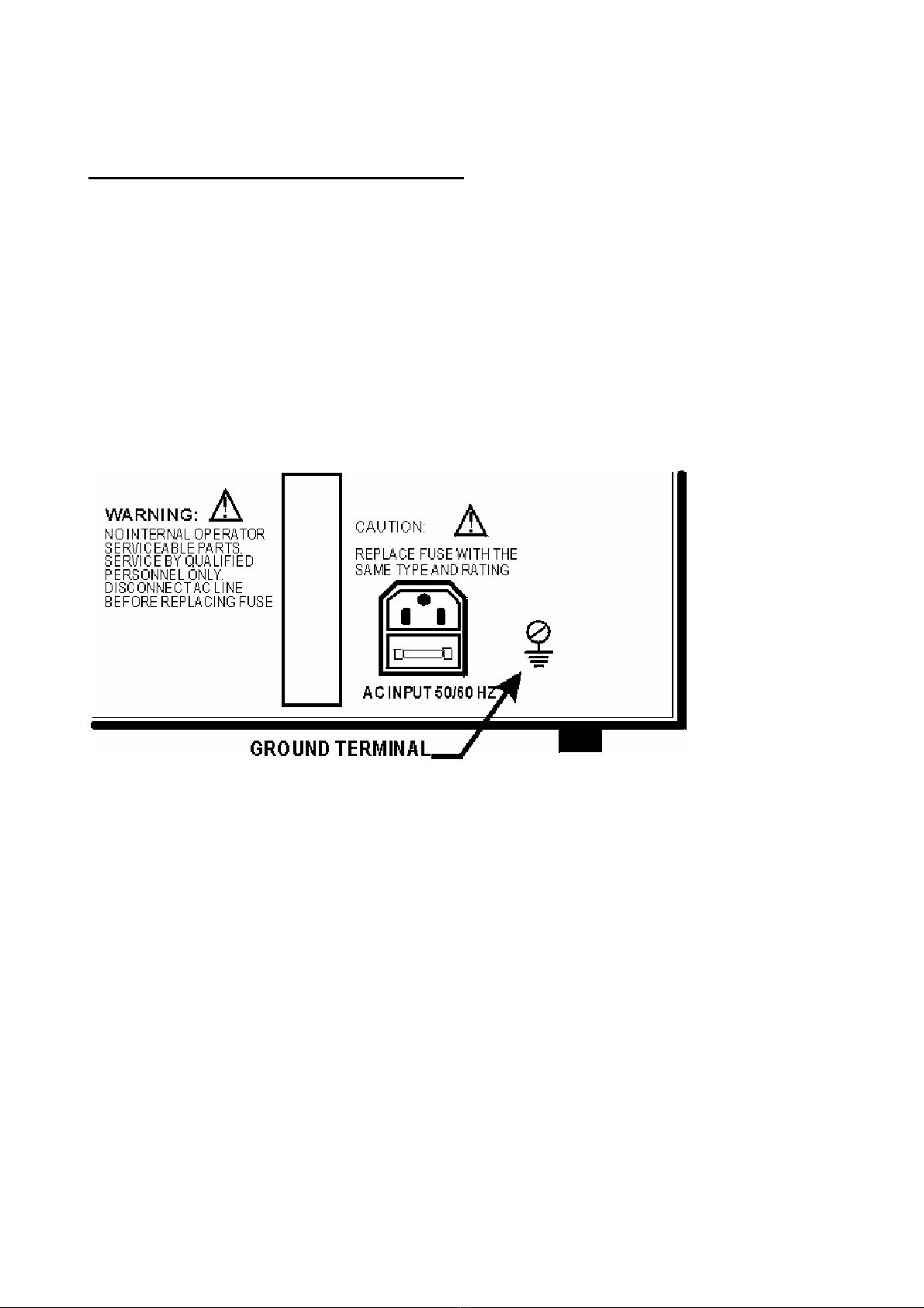
1.2 Earth
There is a “GROUND TERMINAL” at the rear panel of the tester (Diagram. 1). Make sure this
terminal is properly grounded otherwise electric shock may occur to operator when the tester
is malfunction or high potential may accidentally in contact to the chassis.
Diagram. 1
Page 1

1.3 Connecting Voltage Test Lead (Black) to “LOW” Output Terminal
Always connecting Voltage Test Lead (Black) to “LOW” Output Terminal when the tester is
under operation as shown in (Diag.2). Also always check if the test lead is properly
connected to the “LOW” Output Terminal without loosen or fallen off. When tester is under
operation connect the “LOW” Output Terminal to the device under test through the Voltage
Test Lead (Black). Should the “LOW” Output Terminal is not properly connected, the device
under test may have been charged at high voltage that may cause serious electric shock
accident.
MAKE SURE THIS TERMINAL
IS IN GOOD CONTACT WITH
VOLTAGE TEST LEAD (BLACK)
Diagram 2
1.4 Connecting Voltage Test Lead (Red) to “HIGH” Output Terminal.
When the Voltage Test Lead (Black) has been well connected and secured to the “LOW”
Voltage Output Terminal, operator can connect the Voltage Test Lead (Red) to the “HIGH”
Voltage Terminal according to the following steps:
* Press [RESET] button.
* Assure [OUTPUT HIGH VOLTAGE INDICATOR] LED is “OFF”.
* Short the Voltage Test Lead (Black), which is connected to the “LOW”, output terminal to
the “HIGH” output terminal so to make sure that no voltage exists at the “HIGH” output
terminal.
* Insert and connect the “HIGH” Voltage Test Lead (RED) to the “HIGH” output terminal.
* Lastly connect both the Voltage Test Lead (Black) and (RED) to the DUT “Device under
test” for testing.
1.5 End of Test
When test has been finished either temporary or completely, or the tester is not under
operation, make sure the tester is power OFF.
Page 2

(WARNING)
DO NOT TOUCH VOLTAGE TEST LEAD (RED), “HIGH” OUTPUT
TERMINAL, AND DEVICE UNDER TEST DURING OPERATION.
***** When High Voltage Output is “OFF” *****
1.6 Should there be any necessity to make modification in test lead connection, such that
touching the device under test, voltage output test leads, or “HIGH” voltage output terminal is
a must watch out the followings:
* AC Power “OFF”.
* Short circuit between the “LOW” and “HIGH” voltage output terminals.
1.7 AC Power “ON” / “OFF”.
Beware not to switch on AC Power “ON” immediately after turning off the AC Power of the
tester. Operator should wait for a few second to re-switch on the AC Power.
********** Under Emergency Situation **********
1.8 Immediate Actions
Under emergency situations such as en-counting electric shock, device under test or main
tester is burning, in order not to cause any more and serious damage please follows the
following steps:
* Turn off the AC Power immediately.
* Unplug the AC Power from the main source.
*********** Solution To Problems ***********
1.9 Problems
Situation is very dangerous when the following happens:
* The OUTPUT indication light still blinks when [RESET] switch is activated.
* The OUTPUT indication light still blinks when the output voltage meter indicates no voltage
value.
When the above situations happen, the Voltage Output Terminal may have certain amount
of high voltage. In such cases, operator should turn OFF the AC power, unplug the AC
Power from the main source and stop using the tester. Consult the manufacturer or
distributor, and/or return the tester for repair.
* When [START] switch is activated, output voltage value indicates on the display, but
OUTPUT indicator is “OFF”, it shows that the voltage indication lamp may be malfunction.
Please contact the manufacturer or distributor for repair.
Page 3
1.10. The DU-330 Series Tester has 4 selections on AC Input Voltage Range (Pls. see Table 1).

Check the AC power line and select the correct useable voltage range from the “Voltage
Selection Panel” located at the rear panel. There are two types of fuse provided.
Use correct fuse according to Table 1 as shown.
Voltage
Indication Nominal Value Voltage Range Type of Fuse
100
120
100V
115V
90V ~ 110V
104V ~ 125V
4A Fast
4A Fast
220
240
215V
230V
194V ~ 236V
207V ~ 250V
2A Fast
2A Fast
Table 1
Make sure to turn the power switch “OFF” and unplug the input power cord before replacing
the fuses. Open up the fuse storage cabinet located inside the power input socket at the
rear panel of the tester. Remove the burnt fuse and replace it with a new suitable rating
fuse by inserting it into the fuse holder.
(WARNING)
TO AVOID ANY ACCIDENT MAKE SURE TO USE CORRECT SUITABLE
FUSES.
1.11 This tester will perform properly when applied with a clean AC power source. Should the
AC power source fluctuates it is recommended to use an AC Regulator.
1.12. Storage
The tester functions normally under the working environment of 5 °C ∼40 °C, 80% RH., and
is recommended to put into storage at condition of -20 °C ∼70 °C, 80% RH. Do not expose
the tester under sunlight, high temperature, humid, dusty and under vibration environments.
1.13 Warm-up
It is recommended to allow 15 min warm-up time before the tester is put into operation
mode so the tester can perform functionally and accurately according to specified
specifications.
Page 4

2. Overview
2.1 Highlight Features
The DU-330 Series programmable auto withstanding voltage/insulation tester is designed for
automatic, fast, efficient and accurate testing for electrical and electronic products.
Withstanding Voltage Measurement: The DU-331 can generate up to 5KV AC / 15 mA output
whereas the DU-332 can generate up 6KV DC / 7.5 mA as well.
Insulation Measurement: With option IR, the tester can measure insulation resistance ranging
from 1~ 9999 MΩat test voltage which can be set at any value ranging from 100 VDC~ 1000
VDC.
The DU-330 Series has a large LCD display which displays all setting parameters such as
ramp up time, test time, output test voltage, leakage current, high/low leakage current limits,
insulation resistance value, Hi-Lo IR resistance limits, steps, and memory numbers etc. Test
parameters can be recalled from memory that provides efficient and easy way to perform tests
at different parameter setting conditions.
The DU-330 Series equips with comparator for Go/No Go function. Test result is indicated by
both visual “PASS/FAIL” and audio alarm. Signal of test result can be fed externally through its
remote signal output terminals for remote control. With optional RS-232 interface and Scanner
interface one can hook up to an Automatic Handler or a Scanner Box for fast multi-points
testing.
2.2 Product Features
2.2.1 Multi-step Test Mode
DU-330 Series tester provides capability of multi-step test selection. Under single step test
mode, it can be set to perform single Hi-Pot test (AC only for DU-331, and AC or DC for DU-
332), or single IR test with IR Option only. It also can perform multi-step test in specified
sequence at any different setting test steps e.g. (Step 1) AC Hi-Pot Test →(Step 2) Insulation
Resistance Test →(Step 3) DC Hi-Pot Test →any other set of test steps provided test steps
can be recalled from the memory.
2.2.2 Large LED Display
DU-330 Series tester uses a large LCD display. With it’s well display format design, it can
display all setting parameters, test results, step numbers, memory numbers etc.
simultaneously in one display area. This allows the operator to see in the most convenient way
all necessary testing parameters under setting mode, and test results.
2.2.3 Efficient and Convenient Method of Setting
DU-330 Series is designed to provide easy Manu-driven setting method. After one parameter
has been set; it will simply jump to the next setting step automatically. That allows the operator
to start changing or setting the parameters for the next setting step.
Page 5

2.2.4 Saving and Recall Setting Parameter
DU-330 Series has internal memory for storage of setting parameters. It provides 9 groups of
memories and each group has 99 steps of setting parameters. Any of these 9 groups and 99
steps of memory can be recalled for usage or change of parameters. This feature can save
time and effort to set testing parameters whenever is required.
2.2.5 Temporary Saving Memory
Under “SET” mode DU-330 Series tester will store all settings or changes in parameters to
temporary memory. Same setting datum or parameters before tester is power down will be
resumed automatically when power is up again.
2.2.6 Hi-Lo Measure Value Limit Setting and Comparison Testing Function
DU-330 Series provides internal Hi-Lo measure value limits setting and comparison testing
function (both on Hi-Pot test and IR test). This particular function is designed to compare the
tested value of the device under test with both the High and Low limit values. With this function
one can detect if there is any bad contact or test leads that have been accidentally drop off
causing a miss-leading test results, and distinguish good or bad DUT automatically.
2.2.7 Remote Control
DU-330 Series testers provide two “TEST” and “RESET” control signal inputs used to connect
externally to a foot switch or a control box that can control and activate the output signal.
2.2.8 Test Result Signal Output
Test result status such as “PASS”, “FAIL” and “TEST” can be obtained through RELAY
contacts located at the rear panel of the tester for external control.
2.2.9 Key Lock
Key lock function is provided. Under test condition, if Key Lock function is activated, all
function and data entry keys have been locked except the [RESET]and [∆][∇] keys. This can
prevent, under test condition, any sudden changes of test condition such as the output voltage
and leakage current that may cause dangerous accident.
2.2.10 Change of Voltage Rising Time
DU-330 Series testers provide a [RAMP]function which is used to change the time required
for the output voltage to ramp from zero to the preset voltage level.
2.2.11 OFFSET Function
DU-330 Series testers provide an [OFFSET]function which can sample any residual leakage
current occur between the two output terminals under any test mode. This leakage current will
be stored into the memory and its value will be offset or deducted in every test automatically
so to provide a better accurate test result.
2.2.12 Data Hold Function
Under test mode, tested value will be held and displayed on the LED display temporary when
preset test time has reached.
Page 6

3. SPECIFICTIONS.
Model DU-331 DU-332 DU-333
Scan Test 8 ports ± phase
Withstanding Voltage Test (DU331 AC, DU332, 333 AC/DC)
Output Voltage AC: 0~5000V / DC: 0~6000V. Digital setting (4 digits), 10V/ step,
adjustable with^/ ﹀keys.
Voltage Regulation ≤1%+5V
Waveform & Frequency Sine Wave 50Hz/60Hz selectable
Voltmeter Accuracy 4 digits, ±1% of reading +5 digits
Output Current AC: 0.01mA~15.00mA, DC: 0.01mA~7.5mA
Current Meter Accuracy 4 digits, ±(1.5% of reading +5 digits)
Arc Detection Function 0.5mA~15mA(DC0.5mA~7.5mA) 0.01mA/Steps. (0.0mA is OFF)
Test Time 0.5~999.9 Sec (±20mS), 0.1sec/Steps. (0.0 sec is OFF)
Ramp up Time 0.1~999.9 Sec (±20mS), 0.1sec/Steps. (0.0 sec is OFF)
PASS/FAIL Judgment
Windows comparator system
HI-Limit: 0.10~15.00mA, Digital setting (4digits), 0.01mA/Steps.
LO-Limit: 0.05~7.5.00mA, Digital setting (4digits), 0.01mA/Steps.
Arc Detection 0.5mA~15mA(DC 0.5mA ~ 7.5mA) 0.01mA/Steps. (LO-
Limit & Arc Detection setting 0.0mA is OFF)
Judgment Accuracy ±(1% of setting+50uA)
Insulation Resistance Test (Option of DU332/333 only)
Measuring Voltage DC: 100~1000V, Digital setting, 10V/steps.
Voltmeter Accuracy 4 digits, ±(1% of setting +5 digits)
Measuring Range 1~9999MΩ
Measuring Accuracy
≥500V: 1~1000MΩ: ±5% of reading
≥500V: 1001~9999MΩ: ±15% of reading
< 500V: 1~ 200MΩ: ±10% of reading,
< 500V: 201~1000Ω: ±15% of reading
Test Time 0.5~999.9 Sec (±20mS), 0.1sec/Steps. 0.0sec is off
Judgment Waiting time 0.1-999.9 Sec (±20mS), 0.1sec/Steps
PASS/FAIL Judgment
Windows comparator system.
Both HI and LO limit values can be set with the measuring range.
Note: When the lower limit value is greater than 2000 MΩ, a Judgment
wait time of 1.0second or more is necessary.
Judgment Accuracy Same as measurement accuracy.
Test Time 0.5 to 999.9 sec. (±20ms), 0.1sec/Steps. (0.0 sec is OFF.)
Judgment Waiting Time 0.1 to 999.9 sec. (±20ms), 0.1sec/Steps
Test Modes
Auto Test Up to 9 test steps with different test parameters.
Single Test Execution withstanding voltage test or insulation resistance test.
Auto Scanning Test
Link with Model DU330 Scan Box, it performs auto test for objects
having two or more points (Optional Scanner Interface and Box are
required)
Page 7

Source Protection Function
Fast Output Cut off < 0.4ms
Fast Discharge < 0.2s
Panel Operation Lock YES
Power On Data Rally YES
Reset Protection Key YES
Other Function
Display 240x64 Dot Graphic LCM, CFL back light.
Signal Output PASS, FAIL, and TEST with relay contact signal.
Data Hold YES
Judgment Result Display PASS/ FAIL and Alarm.
Memory Storage 01 to 99, 99 groups of memory, each memory include 9 steps.
Remote Control 9 Pins D-type connector, TEST/RESET/RMT ENABLE.
Interlock Function The test voltage cannot be generated unless the interlock input terminal
is short-circuited
Ambient Temperature and Relative Humidity
Specifications range 5 to 35℃(41 to 95℉), 20 to 80﹪RH.
Operable 0 to 40℃(32 to 104℉), 20 to 80﹪RH.
Storage range 20 to 70℃(4 to 158℉), ≦80﹪RH.
Power Requirements
Line Voltage A: 90~110V, B: 104~125V,
C: 194~236V, D: 207~250V.
Frequency 50 or 60 Hz
Power Consumption When no-load: < 70VA
When with Rated Load: >300VA
Insulation Resistance ≧30MΩ, with 500V DC.
Withstanding Voltage 1000V AC, for 1 minute.
Dimension
DU-331/332 365W x 105H x 350D mm.
DU-333 365W x 160H x 350D mm.
Weight
DU-331: Approx.10kg. DU-331: Approx.11kg. DU-331: Approx.15kg.
Accessories
Operation Manual, Power cord set, 3P-2P AC adapter plug,
High voltage test lead wire (1 meter long), 2A fast blow Fuse (in fuse holder), Certificate of
Calibration
Options
Accessory High Voltage Test Bat
Function
Insulation test function (DU 332/333 only)
Analysis Graph: Graph of Measuring amount,
GO/NG counts, Date, Time… for Analysis
Interface RS-232 interface, GP-IB interface, Printer interface,
Scan interface for Scan box DU-330S/380S
Page 8

4. Panel Layout
4.1 FRONT PANEL LAYOUTS.
1. POWER ON/OFF SWITCH
This is an On/Off switch for AC power source. Please refer to Section 1 “Safety Steps Before
Operation” for detail.
2. PROG. /EXIT
This allows tester-entering program set up mode. When this button is pressed LED display
screen will show all set up parameters. A “STEP” sign is shown in reverse video that enables
the tester entering into program set up mode. Operator can key in new or changes of testing
parameters. Also tester can exit programming set up mode by pressing this key once again.
3. ∆∇
Up and Down key. These two keys are being used to change the value of corresponding
highlighted parameters during set up mode. They perform differently under different mode of
operation.
4. ENTEER
This key is used to confirm data set or changed of parameters in set up mode.
5. RECALL/BACK
This key can recall steps and program from the memory or to return to previous set up stage.
Under “RESET” state, pressing this key it will enter into memory management mode under
which operator can call up parameters from the memory. If under set up mode, pressing this
it can return to previous set up parameter.
6. LCD DISPLAY
This is a 240 x 64 LCD display, which enables displaying all setting parameters, test and
comparison results in a comprehensive way.
7. FREQ.
This is to set the test frequency under STANDBY MODE selectively between 50Hz and 60Hz.
8. INITIAL
This is a System Setup Initializing Key. When this key is pressed the System Setup page is
displayed. Under this mode, one can change the interface, all special set up parameters,
default values, and calibration values.
9. STEP MODE
This key enables to set test steps mode and test sequence used.
10. V.ADJ
Under ‘TEST’ mode when pressing this key the output voltage value can be adjusted by
pressing the ∆up and ∇down keys.
Page 9

11. OFFSET
This switch enables the tester to offset any residual leakage current occurs on test leads or
test fixture in used.
12. TEST
When this switch is activated the tester will enter into test mode such that the output
terminals will experience high voltage. All measurement and comparison functions are in
operation.
13. RESET
When activating this switch the tester returns to STANDBY mode. Any output voltage at
output terminals will be cut-off. All comparison test results will be erased too.
14. OUTPUT LED
When this LED blinks it indicates the tester is under test mode. High voltage potential exists
across the output terminals, which should not be touched at all time.
15. OUTPUT TERMINAL
H.V. TERMINAL: A high voltage to a maximum of 6KV DC may be existed at this terminal.
Do not touch it at all time. LOW TERMINAL: This is a low voltage terminal and usually is
grounded with the case.
4.2 REAR PANEL LAYOUTS
1. AC INPUT
This AC power input socket is equipped with a fuse holder containing a fuse suitable for
correct AC voltage range indicated in the AC voltage selection switch.
2. STATUS SIGNAL OUTPUT
There are 4 test result conditional ON/OFF terminals as listed
PASS -- These terminals are in NO condition and are short-circuited when the DUT has been
checked and determined to be good. The short circuit specification is 115VAC at <
0.3A or 24V DC at <1A. Contact duration will be app. 0.5 sec.
FAIL ---- These terminals are always open and short circuited when the DUT fails to meet
with test parameters. The short circuit specification is same as ‘PASS’ mentioned
above. The short circuit state stays until RESET switch is activated.
TEST -- These terminals will be short circuited when tester is under test mode. This allows
control of external signals. The contact specification is same as above, and the
contact state will change until RESET switch is activated.
INTERNAL -- This is a double safety-locking device. TEST can only be operated when LOCK and
only when these terminals are short circuit. The tester cannot activate TEST when
these terminals are open.
Page 10

3. VOLTAGE SELECTOR
These are input voltage range selection switches, which enable the tester for global usage
are 4 different voltage ranges for selection as listed:
a. 90 ∼110 V AC
b. 104 ∼125 V AC
c. 194 ∼236 V AC
d. 207 ∼250 V AC
When correct voltage is selected make sure corresponding fuse used is correct before
turning ON the AC power.
4. FAN
This DC motor fan is used to circulate the air inside in order to prevent the components from
being overheated.
5. GND TERMINAL
This is the ground terminal. Electric shock may occur to operator if this has not been properly
connected to the ground.
6. REMOTE CONNECTOR
A remote control socket is installed for receiving remote control signals for “TEST”, “RESET”
and “RMT-ENABLE” functions. Operation is described in detail in “REMOTE” section of
CHAPTER 5.
7. RS-232 CONNECTOR (OPTION)
A standard RS-232 interface is offered as an option. With the interface the tester can be
communicated with PC for remote control operation.
8. SCAN CONNECTOR (OPTION)
This connector can link up a built-in optional “SCAN INTERFACE CARD” to an optional
scanner, which performs tests for multi-points.
Page 11
5. Operation Instruction
5.1 CAUTIONS - BEFORE OPERATION
1. Make sure the AC power line supply matching the selected voltage range before turning on
the AC power switch.
2. The tester has self-calibration function which performs right after the power switch is “ON”
Should there be any extra-ordinary situation happened turn off the in power switch and un-
plug the AC power source.
5.2 Test Datum Setting Operation
5.2.1 Range of Datum Setting
All datum can be set by pressing the front panel switches and is shown clearly on the
LCD display. Range of datum listed as follow:
1. Test Steps: 1 ∼9
2. Test Mode: AC / DC / IR
3. Hi-Pot Test: 100 ∼5000 VAC (6000 VDC)
4. Insulation Test Voltage: 100 ∼1000 VDC
5. Leakage Current High Limit : 0.10 ∼15.00 AC mA (7.50 DC mA)
6. Leakage Current Lo Limit : 0.05 ∼½ of High Limit or 0.00 mA (OFF)
7. Insulation Resistant High Limit : 0 ∼9999 MΩ(0 MΩ= OFF)
8. Insulation Resistant Lo Limit : 1 ∼9999 MΩ( must be lower than Hi Limit)
9. Test Time : 0.5 ∼99.9 Sec.
10. Ramp up Time : 0.0 ∼99.9 Sec.or 0.0 Sec. (OFF)
11. ARC Test Current : 0.50 ∼15.00 mA (DC 7.50mA) or 0.00 mA
(OFF)
5.2.2 Parameter Setting Procedure
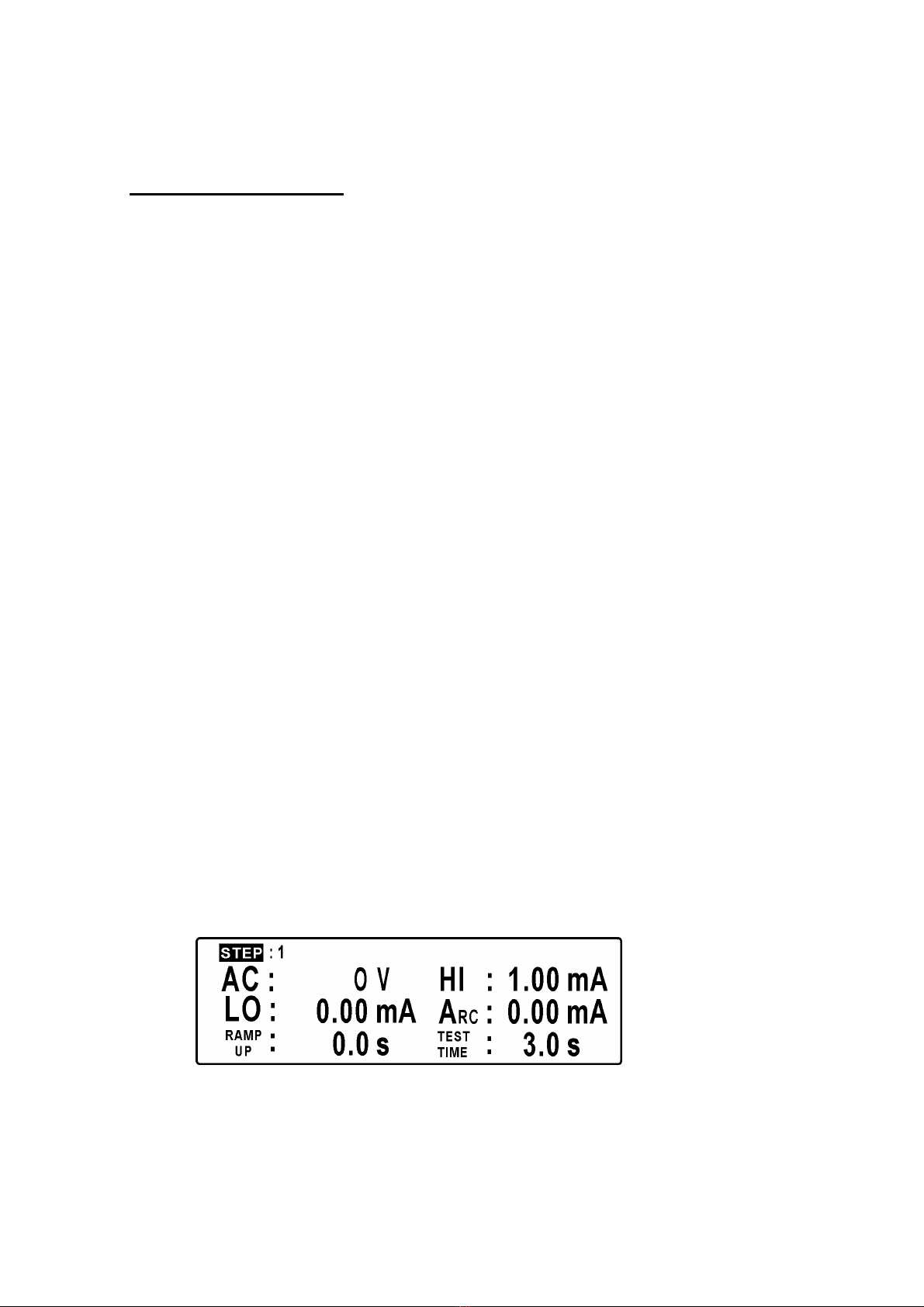
1. Step Setting: 1 to 9
A program page as follow is displayed when [PROG. /EXIT] key is pressed and the
word “STEP” in reverse video appears immediately. Step number 1 to 9 can be
assigned by pressing ∆or ∇. Set data is memorized by pressing [ENTER], and the
cursor automatically jumps to next setting parameter.
Page 12

2. Test Mode Set Up: AC / DC / IR
Test mode can be assigned by pressing ∆or ∇. Setting can be confirmed by
pressing [ENTER] and the cursor automatically jumps to next setting parameter.
3. Leakage Current Hi Limit: 0.10 ∼15.00 mA (DC 7.50mA)
Value of current can be set by pressing the ∆or ∇key and stored into memory after
pressing the [ENTER] and the cursor jumps to next setting parameter.
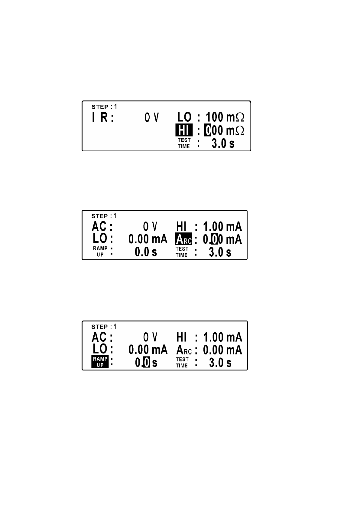
If test mode has been selected as IR, the set up page will be shown as follows. The
reverse video cursor is at Insulation Resistance Lo Limit position. Its value can also
be adjusted by pressing the ∆or ∇key. Set value is also stored into the memory
and the cursor goes to the setting parameter in the next page after pressing
[ENTER].
4. Leakage Current Lo Limit: 0.05 mA ∼½ of the High Limit
The reverse video cursor is now at the Lo Limit position. The current value can be
adjusted as above and can also be set to 0.00mA. This means the low limit
comparison function is not used. The adjusted value is completed and confirmed by
pressing the [ENTER] and the cursor jumps to the next page.
Page 13
If test mode has been selected as IR, the cursor is highlighted at the position of the
value of Insulation Resistance for High Limit. Press the ∆or ∇key to change the
value and confirmed by pressing [ENTER], thus position of the cursor will jump to
next page.
5. ARC Setting: 0.50 ∼15 mA AC (0.50 ∼5.00 mA DC) or (OFF)
The cursor is now in the position of ARC current limit. The value can be
adjusted and set by pressing ∆or ∇key. If the ARC current limit function is
not used enter value of 0.00 mA and press [ENTER]. The cursor will jump to
the next page.
6. Ramp-Up Time Setting: 0.00 ∼99.9 Sec or 0 (OFF)
Ramp-up time is the time required that the output voltage reached to the set
value which can be adjusted or set by pressing the ∆or ∇key. If ramp-up
time control function is not required set the value to 0.00S and press [ENTER]
to store the value, exit and jump to the next page.
Page 14
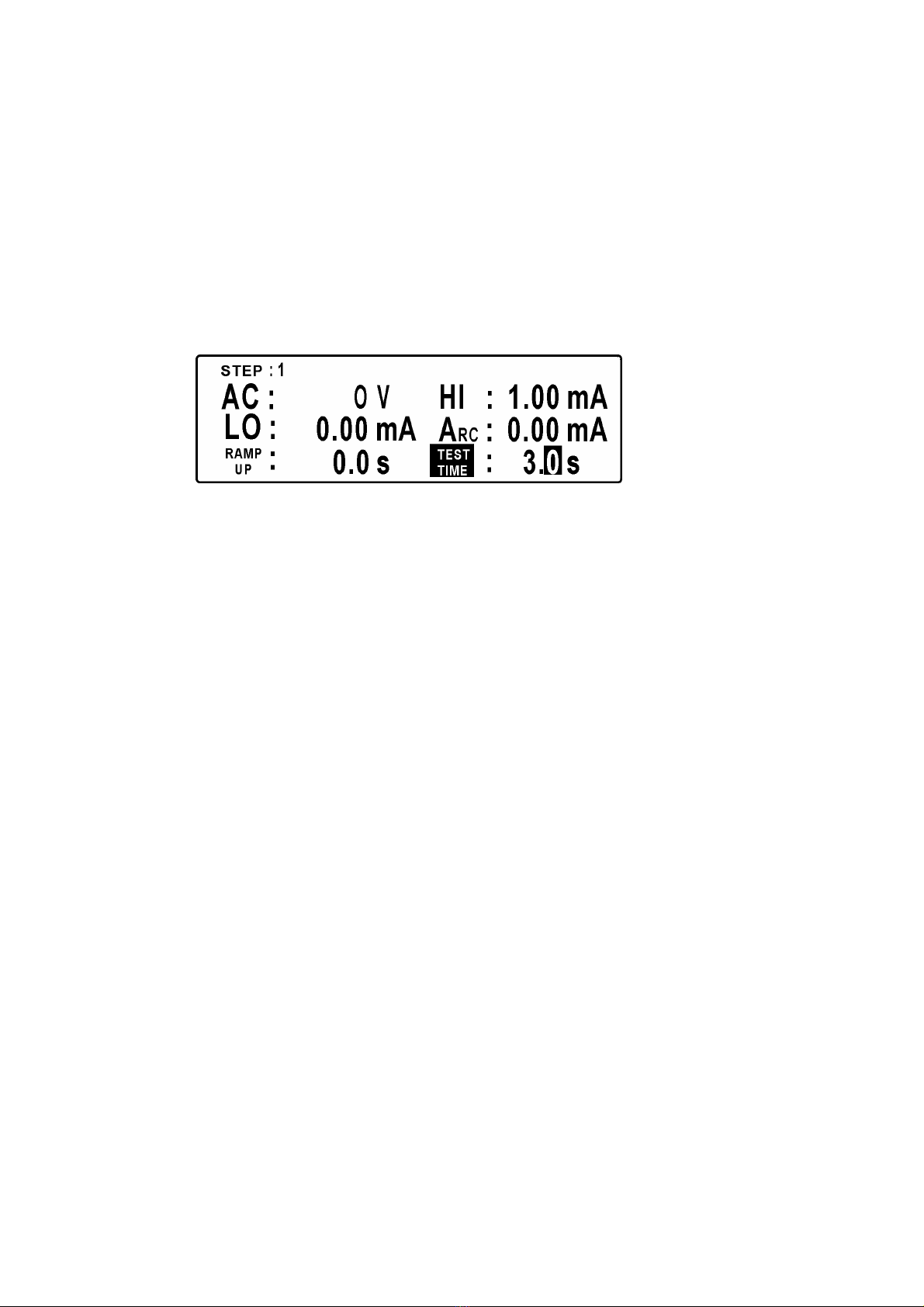
7. Test Time Setting: 0.00 ∼99.9 Sec. or 0.00 Sec. for continuous test
“Test Time” is high-lighted by the reverse video cursor. The assigned length
of test time can be changed by pressing the ∆or ∇key. If 0.00 Sec.is set, the
test will perform continuously until [RESET] is key in. When setting is
completed confirmation is assured by pressing [ENTER]. New setting is
stored into the memory, and setting returns to original ‘Step Setting’ page. To
exit the program press the [PRO/EXIT] key and the reverse video cursor
disappears.
Page 15
This manual suits for next models
3
Table of contents
Popular Test Equipment manuals by other brands


Redtech
Redtech TRAILERteck T05 user manual

Venmar
Venmar AVS Constructo 1.0 HRV user guide

Test Instrument Solutions
Test Instrument Solutions SafetyPAT operating manual

Hanna Instruments
Hanna Instruments HI 38078 instruction manual

Kistler
Kistler 5495C Series instruction manual

Waygate Technologies
Waygate Technologies DM5E Basic quick start guide

StoneL
StoneL DeviceNet CK464002A manual

Seica
Seica RAPID 220 Site preparation guide

Kingfisher
Kingfisher KI7400 Series Training manual

Kurth Electronic
Kurth Electronic CCTS-03 operating manual

SMART
SMART KANAAD SBT XTREME 3G Series user manual

Agilent Technologies
Agilent Technologies BERT Serial Getting started