Delta 50-875 Type II User manual

50-875 Type II
Purificador de aire ambiental
de 3 velocidades con filtro con pliegues
Système de filtration de l’air ambiant
à 3 vitesses avec filtre plissé
Instruction manual
Manuel d’utilisation
Manual de instrucciones
Français (12)
Español (22)
INSTRUCTIVO DE OPERACIÓN, CENTROS
DE SERVICIO Y PÓLIZA DE GARANTÍA.
LÉASE ESTE INSTRUCTIVO
ANTES DE USAR EL PRODUCTO.
www.DeltaMachinery.com
3 Speed AmbIenT AIr CleAner
WITH pleATed FIlTer

2
READ AND UNDERSTAND ALL WARNINGS AND OPERATING INSTRUCTIONS BEFORE
USING THIS EQUIPMENT. Failure to follow all instructions listed below, may result in
electric shock, fire, and/or serious personal injury or property damage.
Woodworking can be dangerous if safe and proper operating procedures are not followed. As with all machinery,
there are certain hazards involved with the operation of the product. Using the machine with respect and caution
will considerably lessen the possibility of personal injury. However, if normal safety precautions are overlooked or
ignored, personal injury to the operator may result. Safety equipment such as guards, push sticks, hold-downs,
featherboards, goggles, dust masks and hearing protection can reduce your potential for injury. But even the best
guard won’t make up for poor judgment, carelessness or inattention. Always use common sense and exercise
caution in the workshop. If a procedure feels dangerous, don’t try it. Figure out an alternative procedure that feels
safer. Your personal safety is your responsibility. For additional information please visit our website
This machine was designed for certain applications only. DELTA®Power Equipment Corporation
strongly recommends that this machine not be modified and/or used for any application other than
that for which it was designed. If you have any questions relative to a particular application, DO NOT use the
machine until you have first contacted DELTA®to determine if it can or should be performed on the product.
If you have any questions relative to its application DO NOT use the product until you have written DELTA®Power
Equipment Corporation and we have advised you. Contact us online at www.DeltaMachinery.com or by mail at
Technical Service Manager, DELTA®Power Equipment Corporation, 4825 Highway 45 North, Jackson, TN 38305.
Information regarding the safe and proper operation of this tool is available from the following sources:
• Power Tool Institute, 1300 Sumner Avenue, Cleveland, OH 44115-2851or online at www.powertoolinstitute.com
• National Safety Council, 1121 Spring Lake Drive, Itasca, IL 60143-3201
• American National Standards Institute, 25 West 43rd Street, 4 floor, New York, NY 10036 www.ansi.org - ANSI 01.1
Safety Requirements for Woodworking Machines
• U.S. Department of Labor regulations www.osha.gov
This manual contains information that is important for you to know and understand. This information relates to
protecting YOUR SAFETY and PREVENTING EQUIPMENT PROBLEMS. To help you recognize this information, we
use the symbols below. Please read the manual and pay attention to these sections.
Indicates an imminently hazardous situation which, if not avoided, will result in death or serious
injury.
Indicates a potentially hazardous situation which, if not avoided, could result in death or serious
injury.
Indicates a potentially hazardous situation which, if not avoided, may result in minor or moderate
injury.
Used without the safety alert symbol indicates potentially hazardous situation which, if not avoided,
may result in property damage.

3
Combining wood and
metal dust can create an explosion or fire hazard. This
unit is intended to filter non-explosive atmospheres
only.
Explosions or fire can result. This air cleaner is
intended for use where only dry airborne dust is
present. Its use should be limited to non-explosive,
non-metallic atmospheres.
1.
A unit incorrectly assembled can cause
injury.
2.
Knowledge is
safety.
3.
4.
Do not use the power cord as a hanging device. A
damaged power cord can cause electrical shock or
electrocution.
5.
A falling unit can cause serious injury.
Always keep a minimum of 7 feet between the bottom
of the unit and the floor surface to allow for sufficient
head clearance. Use only a chain rated for a minimum
of 150 lb. working load to adequately hold the unit.
Use steel S-Hooks that are at least 1/4" in diameter to
suspend the unit from the ceiling. Lag-type bolts used
to suspend the unit from the ceiling must be threaded
at least 1-1/2" into supporting structural members.
6.
7.
Clogged intakes
or exhausts can cause an explosion and/or fire.
8.
Avoid all exposure to rotating parts to prevent
injury.
9.
Dust and other small debris will go directly
to the motor, causing over-heating and the potential for
fire and/or explosion.
10.
Exposed fan blades can
cause severe cuts. Make certain that the unit is
disconnected from the power source.
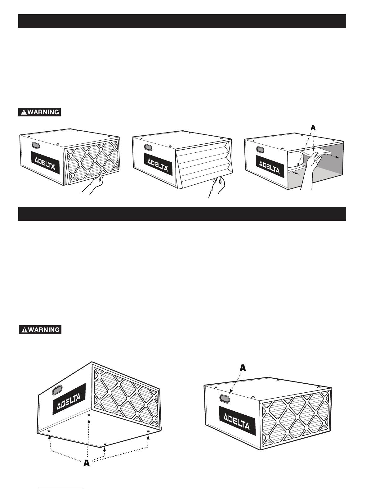
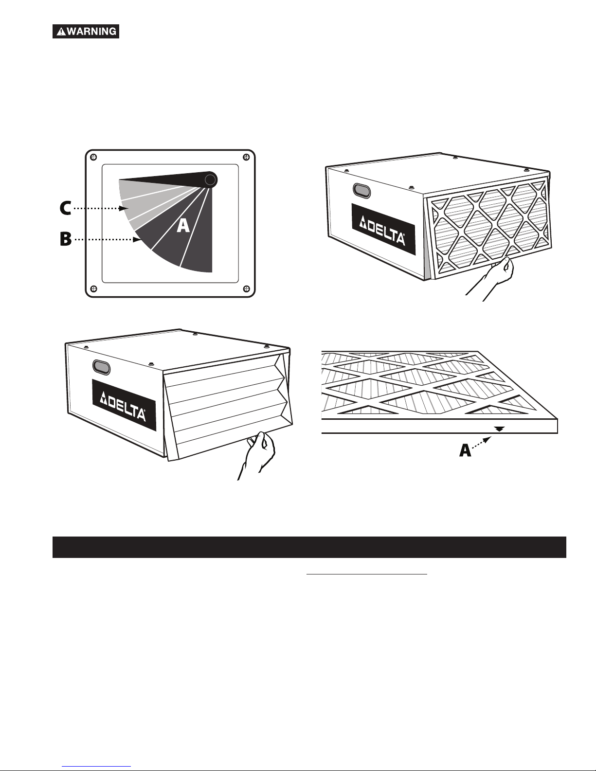
11. Clogged filters
can increase the potential for fire or explosion. Follow
all instructions for changing and cleaning filters.
12.
A damaged
power cord can cause shock or electrocution. Safely
store power cord on the unit to eliminate tripping
hazards.
13.
An accidental start-up can cause
serious injury.
•
Learn the unit’s application and limitations as well as the specific hazards peculiar to it.
• Cluttered areas and benches invite accidents.
• Don’t use this unit in damp or wet locations, or expose it to rain.
Keep work area well-lighted.
• All children and visitors should be kept a safe distance from work area.
• before servicing.
• Before further use of the unit, properly repair or replace any part that is damaged.

4
A separate electrical circuit should be used for your machines. This circuit should not be less than #12 wire and
should be protected with a 20 Amp time lag fuse. If an extension cord is used, use only 3-wire extension cords
which have 3-prong grounding type plugs and matching receptacle which will accept the machine’s plug. Before
connecting the machine to the power line, make sure the switch (s) is in the “OFF” position and be sure that the
electric current is of the same characteristics as indicated on the machine. All line connections should make good
contact. Running on low voltage will damage the machine.
Your machine is wired for 120 volts, 60 HZ alternating current. Before connecting the machine to the power source,
make sure the switch is in the “OFF” position.
In the event of a malfunction or breakdown, grounding provides a path of least resistance for electric current to
reduce the risk of electric shock. This machine is equipped with an electric cord having an equipment-grounding
conductor and a grounding plug. The plug must be plugged into a matching outlet that is properly installed and
grounded in accordance with all local codes and ordinances.
Do not modify the plug provided - if it will not fit the outlet, have the proper outlet installed by a qualified electrician.
Improper connection of the equipment-grounding conductor can result in risk of electric shock. The conductor with
insulation having an outer surface that is green with or without yellow stripes is the equipment-grounding conductor.
If repair or replacement of the electric cord or plug is necessary, do not connect the equipment-grounding conductor
to a live terminal.
Check with a qualified electrician or service personnel if the grounding instructions are not completely understood,
or if in doubt as to whether the machine is properly grounded.
Use only 3-wire extension cords that have 3-prong grounding type plugs and matching 3-conductor receptacles that
accept the machine’s plug, as shown in Fig. A.
Repair or replace damaged or worn cord immediately.
If the machine is intended for use on a circuit that has an outlet that looks like the one illustrated in Fig. A, the
machine will have a grounding plug that looks like the plug illustrated in Fig. A. A temporary adapter, which looks like
the adapter illustrated in Fig. B, may be used to connect this plug to a matching 2-conductor receptacle as shown
in Fig. B if a properly grounded outlet is not available. The temporary adapter should be used only until a properly
grounded outlet can be installed by a qualified electrician. The green-colored rigid ear, lug, and the like, extending
from the adapter must be connected to a permanent ground such as a properly grounded outlet box. Whenever the
adapter is used, it must be held in place with a metal screw.
In Canada, the use of a temporary adapter is not permitted by the Canadian Electric Code.

5
Model 50-875 Type II DELTA®3 Speed Ambient Air Cleaner with Pleated Filter is specifically designed to quietly
circulate and filter non-metallic dust which is generated throughout the work area. The Air Cleaner is furnished
with two filters: an outer filter which filters particles that are five microns and larger, and a secondary disposable
filter that captures 91% of the dust particles that are one micron and larger (one micron = one millionth of a meter).
Because breathing microscopic particles can be a potential health hazard, filtering microscopic dust particles
offers a cleaner and safer environment. This Air Cleaner will filter the air in a room measuring 20’ x 20’ x 8’ either
13, 16, or 18 times an hour, depending on the setting. If desired, multiple units can be used to filter larger areas. An
occasional cleaning and/or replacement of filters is the only required maintenance.
1. Air cleaner
2. Remote Control Unit
(Batteries not included)
3. 1" Eye-Bolts (4)
4. Rubber Feet (4)
5. 5/16" Flange nuts (4)

6
The Air Cleaner is shipped complete in one shipping container. Carefully unpack the Air Cleaner and all loose items
from the shipping container.
Styrofoam blocks have been packed inside the unit for protection. REMOVE THESE BLOCKS (A) Fig. 2 prior to use.
To Remove:
1. Disconnect unit from power source.
2. Remove outer filter by lifting up on the bottom and pulling out (Fig. 2A).
3. Remove inner filter by lifting up on the bottom and pulling out (Fig. 2B).
4. Remove styrofoam blocks (A) Fig. 2C and replace filters.
Determine whether the Air Cleaner will be used on the floor, on a bench, or hanging from an overhead support.
If the Air Cleaner will be used as a mobile unit, proceed to “USING THE AIR CLEANER ON A BENCH OR FLOOR
SURFACE” section. If the unit will be ceiling-mounted, proceed to section “MOUNTING THE AIR CLEANER TO A
CEILING OR OVERHEAD SUPPORT.”
When determining where to mount the air cleaner, always select a location where the air flow is
unrestricted. Do not locate the unit in a corner or near any heating or cooling vents.
Locate (4) self-adhesive rubber feet (A) Fig. 3 supplied with the unit. Carefully place the Air Cleaner on a firm
supporting surface with access to the bottom of the cabinet. Apply a self-adhesive rubber foot (A) Fig. 3 to the
bottom at each corner of the air cleaner cabinet. The rubber feet will help eliminate vibration and will prevent the
possibility of the air cleaner “walking” across the floor or work surface.
The air cleaner cabinet has convenient lifting handles located on either side (one of which is shown at (A) Fig. 4). To
avoid damage to the air filters, carry the air cleaner with the filters positioned away from your body.

7
1. Locate the four 1" eye bolts and the four 5/16" Flange nuts supplied with the unit.
2. Use a flat blade screwdriver (not supplied) to remove the four screws (C) Fig. 5 from the top of air cleaner (D).
3. Thread one flange nut on each bolt approximately 5/16".
4. Thread the eye-bolts (F) Fig. 6 into the four holes where the screws were removed in STEP 2.
Be certain that the flange nuts are tightened against the surface of the air cleaner.
When suspending the air cleaner from the ceiling or other overhead support, use steel s-hooks that are a
minimum of 5/16".
Thread all lag hooks at least 1-1/2" into the supporting structural members.
minimum of
a 150 lb. working load.
When determining a location to mount the unit, the air cleaner will operate more efficiently when the air
flow is unrestricted. Do not locate the unit in a corner or near any heating or cooling vents.
The Air Cleaner is equipped with an in-line rocker
switch (M) Fig.7, located on the power cord (N). To
start or stop the motor, press downward on the rocker
switch, according to the markings on the side. When
you are finished with the air cleaner, turn the switch off
rather than unplug the unit.
The ON-OFF Switch must be turned “ON”
before using the remote control feature.

8
The remote control provided with this unit is not
considered a solid-state device.
The Air Cleaner is equipped with a REMOTE CONTROL
(A) Fig.8A.
The remote requires two (2) AAA batteries (not
supplied). The Battery housing is located underneath
the back cover.
Notice that the remote control has three control buttons
(Fig. 8A): TIME (B), ON/OFF (C), and SPEED (D). These
buttons correspond to the LED sensor panel on the
rear of the machine (K) Fig. 8B.
When the machine is connected to the power
source, a green light (E) will be activated on the panel.
To activate the blower unit, press the “ON/OFF” button
(C) Fig. 8A. The machine will begin in the default speed
of Low or “L” on the sensor panel. Press the SPEED
button once, and the machine will run at the high (or
“H” level). Press the SPEED button again, and the
machine will run at the medium speed (or “M”). Press
the SPEED button a third time, and the machine will
return to the Low Speed mode.
To turn the machine off, press the “ON/OFF” button (C)
Fig. 8A.
This unit has a timer that can be set by remote control.
When the “TIME” button (B) Fig. 8A is pressed on the
remote control, the machine will run for 1/2 hour. (An
LED light will show up on the sensor panel (F) Fig. 8B).
Pressing the “TIME” button again will set the machine
to run for one hour. Notice that the light on the sensor
panel has now moved to the 1H location (G) Fig. 8B.
When the “TIME” button is pressed a third time, the
machine will run for two hours. At this point, the green
light will show up under the two hour location (H).
When you press the “TIME” button the fourth time, the
unit will run for four hours. Notice that the indicator
light (J) glows at the four hour mark.
All of these functions can be manually controlled by
using the two buttons on the sensor panel (K) Fig. 8B.
NOTE: The air cleaner may produce a slight odor for the first few hours of operation due to the protective coating
which is applied to internal components. This odor will dissipate and should be disregarded.
a. bench-top sanding applications.
b. circular saw applications.
c. dry wall applications.
d. shop cleaning applications.
e. floor sanding applications.
f. any other application where non-metallic dust is a factor.
The model 50-875 Type II 3 Speed Ambient Air Cleaner with Pleated Filter has an “air flow” indicator (A) Fig. 9A
located on the left side of the unit. To check the filters, turn the unit “ON”. If the indicator points to “green” (B) Fig.
9A, the filters are clean. Clean (or change) the filters when the indicator points to “red” (C) Fig. 9A as follows:
1. Turn the unit “OFF”.
2. Remove the outer first stage filter (A) Fig. 9B by lifting and pulling out on the bottom of the filter. Replace the
first stage filter depending on its condition. When you replace the outer filter, check to see if the filter has an
air flow arrow (A) Fig 9D. If so, point the arrow inward. If the filter does not have an air flow arrow, install the
filter either way.

9
For operator safety, do not exceed an air pressure of 30 psi.
Do not point the air nozzle toward yourself or anyone else. Always wear safety glasses and a dust
mask when using compressed air.
3. Replace the filter, turn the unit “ON”, and check the air flow indicator again.
4. If the air flow indicator points to “green”, the inner filter is still useable. If the indicator points to “red”, remove the
outer filter, then remove the inner filter (B) Fig. 9C by lifting and pulling out on the bottom of the filter. DO NOT try
to clean the inner filter. It is disposable and must be replaced.
5. After replacing the inner filter, reinstall the outer filter.
For assistance with your machine, visit our website at for a list of service centers or
call the DELTA®Power Equipment Corporation help line at 1-800-223-7278.
AIR FLOW

10
A complete line of accessories is available from your DELTA®Supplier, DELTA®Factory Service Centers, and DELTA®
Authorized Service Centers. Please visit our Web Site www.DeltaMachinery.com for an online catalog or for the
name or your nearest supplier.
To register your tool for warranty service visit our website at www.DeltaMachinery.com.
This warranty does not apply to products sold in Latin America. For products sold in Latin America,
see country specific warranty information contained in the packaging, call the local company or see website for warranty
information.
All DELTA®Machines and accessories are manufactured to high quality standards and are serviced by a network of
DELTA®Factory Service Centers and DELTA®Authorized Service Centers. To obtain additional information regarding
your DELTA®quality product or to obtain parts, service, warranty assistance, or the location of the nearest service
center, please call 1-800-223-7278.

11
Use only identical replacement parts. For a parts list or to order parts, visit our website at www.DeltaMachinery.com/service. You
can also order parts from your nearest factory-owned branch, Authorized Warranty Service Center or by calling Technical
Service Manager at 1-800-223-7278 to receive personalized support from one of our highly-trained representatives.
If your warning labels become illegible or are missing, call
1-800-223-7278
for a free replacement.
All quality tools will eventually require servicing and/or replacement of parts. For information
about DELTA®Power Equipment Corporation, its factory-owned branches, or to locate an
Authorized Warranty Service Center, visit our website at
or call our Customer Care Center at 1-800-223-7278. All repairs made by our service centers are fully
guaranteed against defective material and workmanship. We cannot guarantee repairs made or attempted by
others. By calling this number you can also find answers to most frequently asked questions 24 hours/day.
You can also write to us for information at DELTA®Power Equipment Corporation, 4825 Highway 45 North,
Jackson, TN 38305 - Attention: Technical Service Manager. Be sure to include all of the information shown
on the nameplate of your tool (model number, type, serial number, date code, etc.)
FOR YOUR OWN SAFETY
1. READ AND UNDERSTAND
INSTRUCTION MANUAL
BEFORE OPERATING AIR
CLEANER.
2. To reduce the risk of injury,
disconnect from power supply
before servicing or changing
filters.
3. When ceiling mounted,
install Air Cleaner at least 7
feet above floor.
4. If used, ceiling mounts must
be anchored to building
structure. Never secure
mounts to dry wall, drop
ceiling tile/frame or other
non-structural members.
5. To reduce the risk of electrical
shock, do not expose to water
or rain.
6. Use only for the collection of
dry airborne dust. Never duct
the Air Cleaner directly to a
machine. Never use the Air
Cleaner to dissipate fumes
or smoke.
PARA SU PROPIA SEGURIDAD
1. LEA Y ENTIENDA EL MANUAL DE
INSTRUCCIONES ANTES DE
OPERAR EL LIMPIADOR DE AIRE.
2. Desconecte la unidad de la fuente
de energía antes de renidar
servicio o cambiar filtros para
reducir el riesgo de lesionamiento.
3. Instale el Limpiador de Aire por lo
menos 213 cm sobre el nievel del
piso cuando se trate de una
instalación de techno.
4. De utilizarse, los montajes de
techno deben anclarse a la
estructura del edificio. Jamás
afiance los mentajes al muro en
seco, lozas o marcos de platones
u otros miembros no estructurales.
5. No exponga la unidad al agua ni
la lluvia para reducir el riesgo de
choques eléctricos.
6. Utilice la unidad soló para la
recolección de polvo aéreo seco.
Jamás conduzca el Limpiador de
Aire directamente a una máquina.
Jamás utilice el Limplador de Aire
para disipar emanaciones o humo.
410-09-752-0017
To reduce risk of injury from moving parts, unplug before
servicing. Keep hands away from moving parts. Only
operate with air filters installed.
Desenchute la máquina antes de rendir servicio para
reducir el riesgo de lesionamientos ocasionados por
piezas en movimiento. Aleje las manos de las piezas
en movimiento. Opere solo con los filtros de aire
instalados.
410-09-752-0018

12
Le fait de ne pas respecter toutes les instructions ci-dessous,
peut avoir pour conséquence : choc électrique, incendie et/ou blessures graves ou dégâts matériels.
Le travail du bois peut être dangereux si des procédures d’utilisation sécuritaires et adéquates ne sont pas
respectées. Comme c’est le cas pour toute pièce de machinerie, certains dangers sont assortis à l’utilisation de
ce produit. En utilisant cet appareil selon les directives et avec prudence, vous réduirez grandement la possibilité
de blessures. Cependant, si les précautions normales de sécurité sont négligées ou ignorées, la personne utilisant
l’appareil pourra être blessée. L’équipement de sécurité comme les dispositifs de protection, bâtons poussoir,
dispositif de retenue à ressort, cales-guide, lunettes, masques anti-poussière et protecteurs d’oreilles peut réduire
les risques de blessures. Mais même les dispositifs de protection les plus efficaces ne pourront vous protéger
contre un manque de jugement, de soin ou d’attention. Utilisez toujours votre bon sens et faites preuve de prudence
dans l’atelier. Si une manœuvre vous semble dangereuse, ne la tentez pas. Essayez plutôt de trouver une autre
solution qui vous paraît plus sûre. : Vous êtes responsable de votre propre sécurité. Pour des
renseignements complémentaires, rendez-vous sur notre site web à l’adresse
Cet appareil a été conçu seulement pour certains types d’utilisation. DELTA®Power
Equipment Corporation recommande fortement que cet appareil ne soit ni modifié ni utilisé à
toute autre fin que celles pour lesquelles il a été conçu. Si vous avez des questions sur un type d’utilisation en
particulier, N’UTILISEZ PAS l’appareil avant d’avoir d’abord contacté DELTA®pour déterminer si elle peut ou si elle
devrait être réalisée avec ce produit.
Si vous avez des questions sur son utilisation, N’UTILISEZ PAS le produit tant que vous n’avez pas écrit à
DELTA®Power Equipment Corporation et obtenu une réponse de leur part. Contactez-nous en ligne sur www.
DeltaMachinery.com ou par courrier à l’adresse suivante : responsable du service technique, DELTA®Power
Equipment Corporation, 4825 Highway 45 North, Jackson, TN 38305.
• Les informations concernant l’utilisation sûre et correcte de cet outil sont disponibles auprès des sources suivantes :
• Power Tool Institute, 1300 Sumner Avenue, Cleveland, OH 44115-2851 ou en ligne sur HYPERLINK http://www.
powertoolinstitute.com/ www.powertoolinstitute.com
• National Safety Council, 1121 Spring Lake Drive, Itasca, IL 60143-3201
• American National Standards Institute, 25 West 43rd Street, 4 floor, New York, NY 10036 HYPERLINK http://www.
ansi.org/ www.ansi.org - ANSI 01.1 Exigences de sécurité pour machines à bois
• U.S. Department of Labor regulations www.osha.gov
Ce manuel contient des informations qu’il est important de connaître et de comprendre. Ces informations ont pour
but d’assurer VOTRE SÉCURITÉ et de PRÉVENIR LES PROBLÈMES D’ÉQUIPEMENT. Pour vous aider à reconnaître
ces informations, nous utilisons les symboles ci-dessous. Veuillez lire le manuel et prêter attention à ces sections-là.
indique une situation dangereuse imminente qui, si elle n’est pas évitée, provoquera la mort ou une
blessure grave.
indique une situation dangereuse potentielle qui, si elle n’est pas évitée, provoquera la mort
ou une blessure grave.
indique une situation dangereuse potentielle qui, si elle n’est pas évitée, peut provoquer une
blessure mineure ou modérée.
utilisé sans le symbole d’alerte de sécurité indique une situation potentiellement dangereuse qui,
si elle n’est pas évitée, peut entraîner des dommages matériels.

13
Le fait de combiner de la poussière de bois et
de métal peut générer un danger d’explosion ou
d’incendie. Cet appareil est conçu pour filtrer
uniquement des atmosphères non explosives.
Des explosions ou incendies peuvent
en résulter. Ce système de filtration de l’air est
conçu pour une utilisation où seule une poussière
sèche est présente dans l’air. Son utilisation devrait
être limitée aux atmosphères non explosives et non
métalliques.
1. faire fonctionner cet appareil tant qu’il n’est
pas complètement monté et installé en respectant
les instructions. Un appareil qui n’est pas monté
correctement peut provoquer des blessures.
2. à votre supérieur, instructeur
ou à une autre personne qualifiée, si vous n’êtes pas
familier avec le fonctionnement de cet appareil. Vos
connaissances sont garantes de votre sécurité.
3. et
connexions électriques recommandés pour éviter un
choc électrique ou une électrocution.
4.
. Ne pas utiliser le cordon
d’alimentation comme un dispositif d’accrochage. Un
cordon d’alimentation endommagé peut provoquer un
choc électrique ou une électrocution.
5. à une structure de
support permanente ou fixe quand il est suspendu
au plafond. La chute d’un appareil peut provoquer
de graves blessures. Toujours garder un minimum de
2,15 m (7 pieds) entre le fond de l’appareil et la surface
du plancher pour garantir une distance suffisante
au-dessus de la tête. Utilisez uniquement une chaîne
capable de soutenir une charge de travail minimum de
68,2 kg (150 livres) de façon à bien maintenir l’appareil.
Utilisez des crochets d’acier en S d’un diamètre d’au
moins 6,4 mm (1/4 po) pour suspendre l’appareil au
plafond. Les tire-fonds utilisés pour suspendre
l’appareil au plafond doivent être filetés sur au moins
38 mm (1 1/2 po) dans la charpente.
6. cet appareil ou le fixer solidement
à la surface de travail quand il est utilisé de façon
portable pour éviter les blessures potentielles et/ou
d’endommager l’appareil.
7.
avant de démarrer
l’appareil. Des zones d’entrée ou de sortie bouchées
peuvent provoquer une explosion et/ou un incendie.
8.
Évitez tout contact avec les
pièces rotatives pour prévenir les blessures.
9.
La poussière et autres petits
débris iront directement au moteur, ce qui provoquera
une surchauffe et un incendie et/ou une explosion
potentiels.
10. d’enlever ou de remplacer le ou
les filtres lorsque l’appareil est en marche. Les pales
apparentes du ventilateur peuvent provoquer de graves
coupures. Assurez-vous que l’appareil est débranché
de la source d’alimentation.
11. en excellent état. Des filtres
bouchés peuvent augmenter le risque d’incendie ou
d’explosion. Suivez les consignes pour changer et
nettoyer les filtres.
12. dans un endroit où le cordon
d’alimentation ne peut pas être endommagé. Un
cordon d’alimentation abîmé peut provoquer un choc
électrique ou une électrocution. Bien ranger le cordon
d’alimentation sur l’appareil pour éviter que quelqu’un
ne trébuche dessus.
13. et le débrancher de la
source d’alimentation avant d’installer ou d’enlever
des accessoires, avant d’ajuster ou de modifier des
réglages ou avant de faire des réparations. Une mise en
route accidentelle peut provoquer de graves blessures.
•
Apprenez l’utilisation de l’unité et ses limites ainsi que les risques spécifiques qui lui sont
propres.
• Les aires et bancs de travail encombrés attirent les accidents.
• N’utilisez pas cet appareil dans un endroit humide
ou mouillé, et ne l’exposez pas à la pluie.Gardez votre aire de travail bien éclairée.
• Tous les enfants et visiteurs doivent demeurer à une distance
sécuritaire de l’aire de travail.
• avant toute opération d’entretien.
• Avant d’utiliser l’appareil, bien réparer ou remplacer toute pièce
endommagée.

14

15
Le système de filtration de l’air DELTA®modèle 50-875 Type II est spécifiquement conçu pour faire circuler et filtrer
silencieusement la poussière non métallique générée au sein de l’aire de travail. Le système de filtration de l’air
est fourni avec deux filtres : un filtre externe filtrant les particules de cinq microns et plus, et un filtre secondaire
jetable qui capte 91 % des particules de poussière d’un micron et plus (un micron = un millionième de mètre).
Étant donné qu’inhaler des particules microscopiques peut être un danger pour la santé, la filtration des particules
microscopiques de poussière offre un environnement plus propre et plus sûr. Ce système de filtration de l’air sera
en mesure de filtrer l’air d’une pièce mesurant 6 x 6 x 2,45 m (20 pi x 20 pi x 8 pi), 13, 16 ou 18 fois par heure, selon
le réglage. Si vous le souhaitez, plusieurs appareils peuvent être utilisés pour filtrer des zones plus vastes. Un
nettoyage et/ou le remplacement occasionnel des filtres est le seul entretien nécessaire.
1. Système de filtration de l’air
2. Télécommande
(Piles non comprises)
3. Boulons à œil (4) de 2,54 cm (1 po)
4. Supports en caoutchouc (4)
5. Écrous à bride de 5/16-20 (4)

16
1. Débrancher l’appareil de la source d’alimentation.
2. Retirer le filtre externe en soulevant le bas et en tirant vers l’extérieur (Fig. 2A).
3. Retirer le filtre interne en soulevant le bas et en tirant vers l’extérieur (Fig. 2B).
4. Retirer les blocs de styromousse (A) Fig. 2C et remplacer les filtres.

17
1. Prenez les 4 boulons à œil de 2,54 cm (1 po) et les 4 écrous à bride de 5/16 fournis avec l’appareil.
2. Utilisez un tournevis plat (non fourni) pour enlever les 4 vis (C) Fig. 5 sur le dessus du système de filtration de l’air (D).
3. Vissez un écrou à bride sur chaque boulon d’environ 19,1 mm (5/16" po).
4. Placez les boulons à œil (F) Fig. 6 dans les 4 trous d’où les vis ont été retirées à l’ÉTAPE 2.
REMARQUE : Assurez-vous que les écrous à bride sont bien serrés à la surface du système de filtration de l’air.
REMARQUE : Pour fixer l’appareil au plafond ou sur un support en hauteur, utilisez des crochets d’acier en S d’un
diamètre d’au moins 6,4 mm (5/16 po).
REMARQUE : Placez tous les tire-fonds à au moins 38 mm (1 1/2 po) dans la charpente.
Le système de filtration de l’air est équipé d’un
interrupteur à bascule en ligne (M) Fig.7, situé sur le
cordon d’alimentation (N). Pour mettre en route ou
arrêter le moteur, appuyez vers le bas sur l’interrupteur
à bascule, en suivant les instructions sur le côté.
Lorsque vous avez fini d’utiliser le système de filtration
de l’air, éteignez-le en appuyant sur l’interrupteur plutôt
que de le débrancher.
: L’interrupteur MARCHE/ARRÊT
(ON-OFF) doit être mis sur « ON » avant d’utiliser la
télécommande.

18
Pour réduire le risque
d’incendie ou de choc
électrique, ne pas utiliser cet appareil avec tout
dispositif de contrôle de vitesse à semi-conducteur.
La télécommande fournie avec cet appareil n’est pas
considérée comme un dispositif de contrôle de vitesse
à semi-conducteur.
Le système de filtration de l’air est équipé d’une
TÉLÉCOMMANDE (A) Fig.8A.
REMARQUE : La télécommande nécessite deux (2)
piles AAA (non fournies). Le compartiment à piles est
situé sous le couvercle arrière.
Notez que la télécommande possède trois boutons de
commande
: Quand l’appareil est branché à la source
d’alimentation, un voyant vert (E) s’allume sur le
panneau.
Pour mettre en route l’unité de ventilation, appuyez sur le
bouton MARCHE/ARRÊT (ON/OFF) (C) Fig. 8A. L’appareil
commencera avec la vitesse par défaut, qui est une
vitesse basse et qui correspondra à « L » (pour Low =
basse) sur le panneau capteur. Appuyez une fois sur le
bouton VITESSE (SPEED), et l’appareil tournera à grande
vitesse qui correspondra à « H » (pour High = grande).
Appuyez à nouveau sur le bouton VITESSE (SPEED) et
l’appareil tournera à vitesse moyenne (ou « M »). Appuyez
sur le bouton VITESSE (SPEED) une troisième fois et
l’appareil repassera en mode vitesse basse.
Pour éteindre l’appareil, appuyez sur le bouton
MARCHE/ARRÊT (ON/OFF) (C) Fig. 8A.
Cet appareil possède une minuterie qui peut être
réglée avec la télécommande.
Lorsque vous appuyez sur le bouton « DURÉE »
(TIME) (B) Fig. 8A sur la télécommande, l’appareil
fonctionnera pendant 1/2 heure. (Un voyant LED
apparaîtra sur le panneau capteur (F) Fig. 8B). Si vous
appuyez une nouvelle fois sur le bouton « DURÉE »
(TIME), l’appareil sera réglé pour fonctionner pendant
une heure. Notez que le voyant sur le panneau capteur
vient alors se placer sur 1H (G) Fig. 8B. Lorsque vous
appuyez sur le bouton « DURÉE » (TIME) une troisième
fois, l’appareil fonctionnera pendant deux heures. À ce
moment-là, le voyant vert sera sur 2 heures (H). Si vous
appuyez une quatrième fois sur le bouton « DURÉE »
(TIME), l’appareil fonctionnera pendant quatre heures.
Notez que le voyant (J) se trouve sur quatre heures.
Toutes ces fonctions peuvent être contrôlées
manuellement en utilisant les deux boutons du
panneau capteur (K) Fig. 8B.
: Le système de filtration de l’air peut dégager une légère odeur dans les premières heures d’utilisation
en raison du revêtement de protection recouvrant les composants internes. Cette odeur se dissipera, aussi n’en
tenez pas compte.
: Ne jamais faire fonctionner le système de filtration de l’air sans que les filtres soient en place.
a. d’opérations de ponçage.
b. d’utilisations d’une scie circulaire.
c. de poses de cloisons sèches.
d. du nettoyage d’atelier.
e. de ponçages de plancher.
f. de toute autre activité faisant intervenir des poussières non-métalliques.
Le modèle 50-875 Type II de système de filtration de l’air possède un indicateur d’« écoulement de l’air » (A) Fig. 9A
situé sur le côté gauche de l’appareil. Pour vérifier les filtres, mettez l’appareil sur « MARCHE » (ON). Si l’indicateur
est sur « vert » (B) Fig. 9A, les filtres sont propres. Nettoyez (ou changez) les filtres lorsque l’indicateur est sur
« rouge » (C) Fig. 9A de cette façon :
1. Mettez l’appareil sur « ARRÊT » (OFF).
2. Retirez le filtre externe de première étape (A) Fig. 9B en soulevant le bas et en tirant le filtre vers l’extérieur.
Remplacez le filtre de première étape si son état l’exige. Lorsque vous remplacez le filtre externe, vérifiez s’il
possède une flèche indiquant la direction de l’écoulement de l’air (A) Fig. 9D. Si c’est le cas, placez le filtre de
façon à ce que la flèche soit dirigée vers l’intérieur. Si le filtre ne possède pas de flèche indiquant la direction
de l’écoulement de l’air, installez le filtre dans n’importe quel sens.

Pour des raisons de sécurité, ne pas dépasser une
pression d’air de 30 psi. Ne pas diriger le gicleur d’air dans votre direction ou dans celle
de quiconque. Toujours porter des lunettes de sécurité et un masque anti-poussière lorsque vous utilisez de l’air
comprimé.
3. Remplacez le filtre, mettez l’appareil en route et vérifiez à nouveau l’indicateur d’écoulement de l’air.
4. Si l’indicateur d’écoulement de l’air est sur « vert », le filtre interne est toujours utilisable. Si l’indicateur est sur
« rouge », retirez le filtre externe, puis le filtre interne (B) Fig. 9C en soulevant le bas et en tirant le filtre vers
l’extérieur. NE PAS essayer de nettoyer le filtre interne. Il est jetable et doit être remplacé.
5. Une fois le filtre interne remplacé, réinstallez le filtre externe.
Pour une assistance sur votre appareil, rendez-vous sur notre site à l’adresse www.DeltaMachinery.com pour
obtenir la liste des centres de service ou appelez l’assistance de DELTA®Power Equipment Corporation au
1 800 223-7278.
AIR FLOW

20
Pour l’enregistrement de votre appareil auprès du service de la garantie, rendez-vous sur notre site à l’adresse
www.DeltaMachinery.com.
Tous les appareils et tous les accessoires DELTA®sont fabriqués selon des normes de qualité exigeantes et sont
soutenus par un réseau de centres de service du fabricant et de centres de service DELTA®autorisés. Pour en
savoir plus sur votre produit de qualité DELTA®, obtenir des pièces, du service, une assistance quant à la garantie ou
l’emplacement du centre de service le plus proche de chez vous, veuillez composer le 1 800 223-7278.
This manual suits for next models
1
Table of contents
Languages:
Other Delta Air Cleaner manuals