Shihlin electric SS2 Series User manual

Safety Instructions
Safety Instructions
When using Shihlin inverters, please follow the installation to ensure the safety of user and others.
The following instructions will be classified and described by icons:
DANGER It means dangerous instructions, and incorrect handling may result in death or
severe injury.
CAUTION It means caution instructions. Incorrect handling may result in injury or property
damage.
It means caution and execution need to be done. Please operate according to the
instructions.
ANGER
Inverters must be used on the location except corrosive gas, water, flammable gas.
Please operate far from flammable substance or explosives.
Please do not lay the inverter on an intense trembling or shaking occasion.
Do not operate wires soaked under oil or water.
Prohibit touching any part in the inverter when power is ON to avoid electric shock.
hree-phase power cannot be connected to terminal U/ 1, V/ 2, W/ 3.
he terminal of the inverter must be correctly grounded.
Do not conduct wiring when the power is ON.
CAUTION
Do not conduct hi-pot test on internal components of the inverter, for semiconductor
is easily damaged by high voltage.
here are CMOS IC components on PCBAs which are especially sensitive to static
electricity. Please do not touch PCBAs before taking anti-static measures.
Even if the motor stops, a charge may still remain in the main circuit terminals of
the inverter with hazardous voltages.
Only qualified persons are allowed to install, wire and maintain the inverter.
After some functions are set, the motor may start immediately once power is ON.
Please choose the safe area to install the inverter, avoiding heat, direct sunlight,
moisture humidity and splashing of droplets.
When wiring between the inverter and motor is too long, it may damage the layer
insulation of the motor. A reactor can be mounted between inverter and motor,
avoiding insulation is damaged.
For the installation power system of rated voltage, it cannot be over 240V for 220
series; it cannot be over 480V for 440 series.
Only qualified personnel familiar with wiring is allowed to perform wiring.
For the installation direction and method, please refer to the regulations.
Make sure to use the temperature in a safe range.
Please follow the installation to use the voltage.
When there are problems in operation, please first unload the motor, after zero-load
operation is OK, and then connect to the machine.
Please confirm whether the inverter power is in line with the motor power.
Before running, please confirm whether the emergency switch can operate normally.
Power wire, U, V, W wires and signal wire should not be stranded, but separately.
Please turn off the power if it is not used for a long time.

Contents
contents
Contents
1. User Manual .................................................................................................................................................... 1
2. Delivery Check ................................................................................................................................................ 3
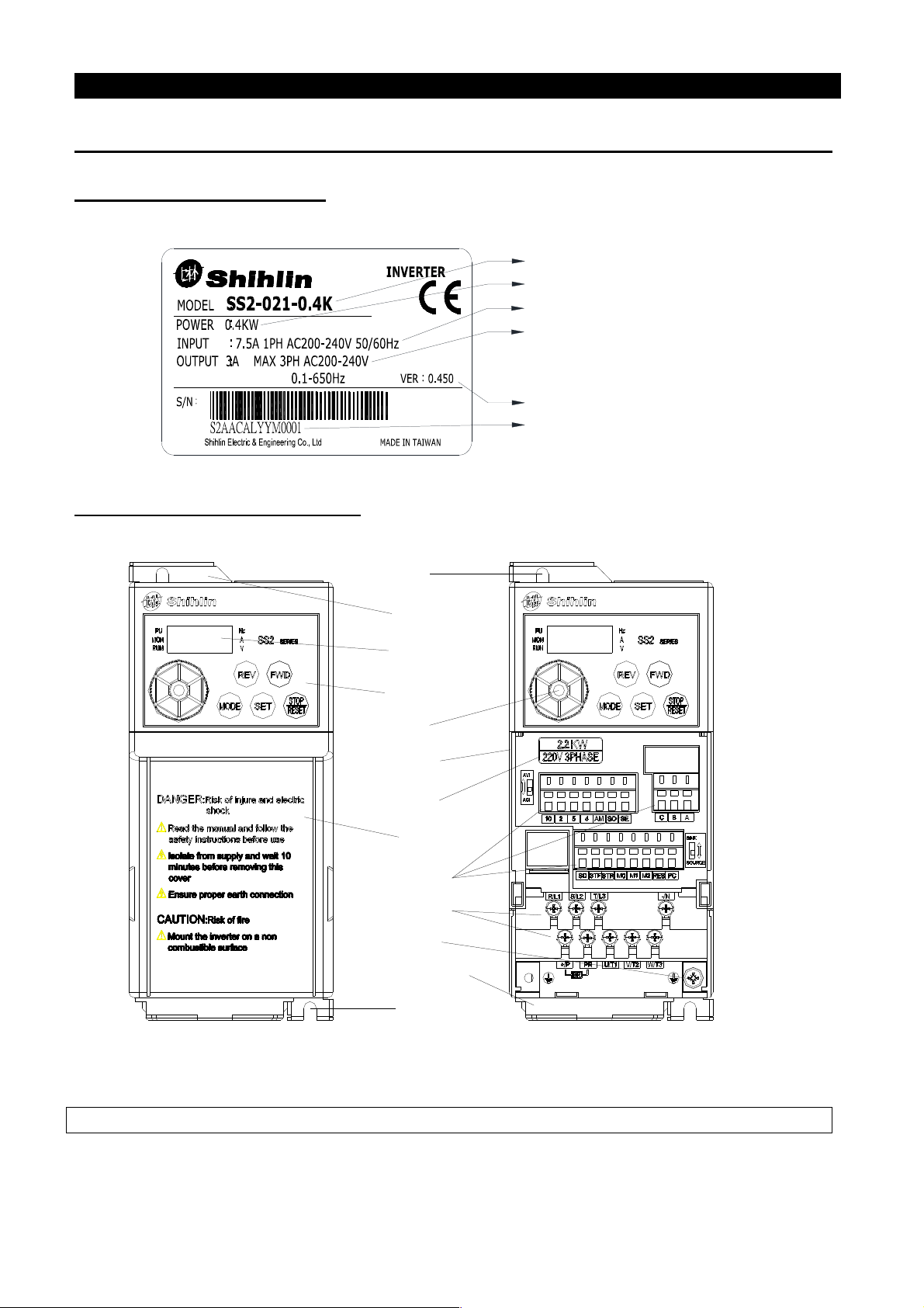
2.1 Nameplate Instruction ..................................................................................................................................................... 3
2.2 Type Instruction .............................................................................................................................................................. 3
2.3 Order Code Description .................................................................................................................................................. 3
3. Introduction of Shihlin Inverter .................................................................................................................... 4
3.1 Electric Specification .................................................................................................................................................... 4
3.2 Common Specification (Inverter Characteristics) ...................................................................................................... 6
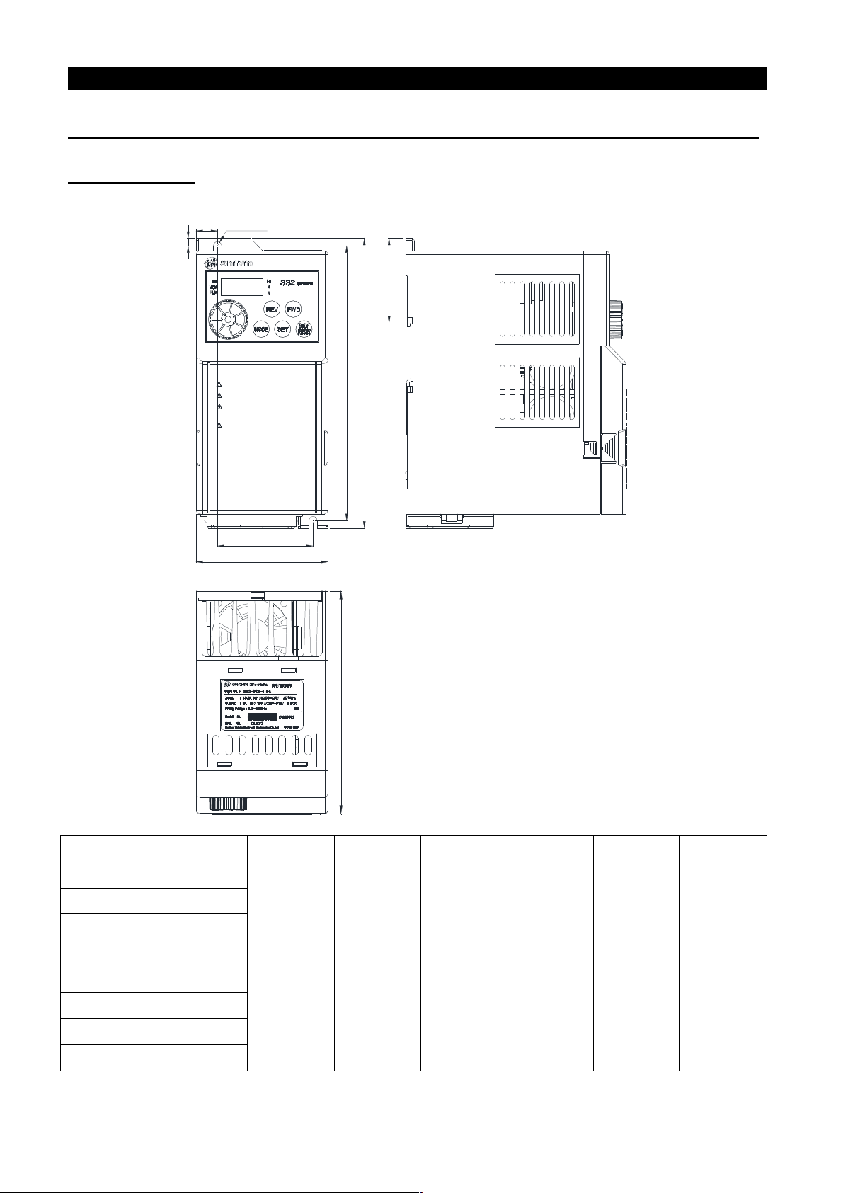
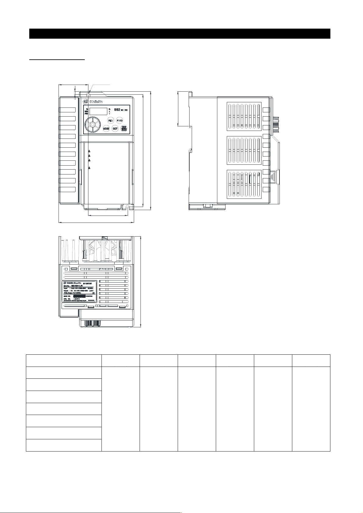
3.3 Mechanical Dimensions ................................................................................................................................................
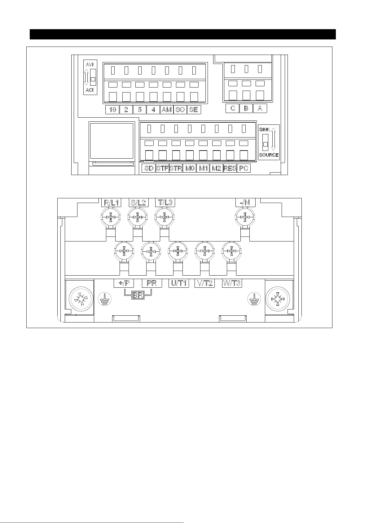
3.4 Name of Each Part ...................................................................................................................................................... 10
3. Installation and Wiring ............................................................................................................................................... 12
3.6 Selection of Peripheral Equipments .......................................................................................................................... 25
4. Primary peration ....................................................................................................................................... 31
4.1 Operation Modes of the Inverter ............................................................................................................................... 31
4.2 Basic Operation Procedures for Different Modes .................................................................................................... 36
4.3 Operation ..................................................................................................................................................................... 40
5. Parameter Description ................................................................................................................................. 42
.1 Torque Boost (P.0, P.46) V/F .................................................................................................................................. 45
.2 Range of the Output Frequency (P.1, P.2, P.18) ........................................................................................................ 46
.3 Base Frequency and Base Frequency Voltage (P.3, P.19, P.47) ................................................................................ 47
.4 Multi-speed (P.4~P.6, P.24~P.27, P.142~P.149) .......................................................................................................... 4
. Acceleration/Deceleration Time (P.7, P.8, P.20, P.21, P.44, P.4 ).............................................................................. 49
.6 Electronic Thermal Relay Capacity (P.9) .................................................................................................................. 51
.7 DC Injection Brake (P.10, P.11, P.12) ......................................................................................................................... 51
.8 Starting Frequency (P.13) ........................................................................................................................................... 52
.9 Load Pattern Selection (P.14, P.98, P.99, P.162~P.169) ............................................................................................. 53
.10 JOG Mode (P.1 , P.16) .............................................................................................................................................. 56
.11 Stall Prevention (P.22, P.23, P.66) ............................................................................................................................. 56
.12 Output Frequency Filter Constant (P.28) ................................................................................................................ 57
.13 Acceleration/deceleration Curve Selection (P.29, P.2 ~P.2 8) ............................................................................. 5
.14 Regenerative Brake (P.30, P.70) ............................................................................................................................... 61
.1 Soft-PWM Selection (P.31) ....................................................................................................................................... 61
.16 Communication Function (P.32, P.33,P.34, P.36, P.48~P. 3, P.1 3~P.1 4) ............................................................ 62
.17 Communication Running and Speed Command(P.3 ) ..................................................................................... 79
.18 Speed Display (P.37, P.2 9) ....................................................................................................................................... 0
.19 Voltage Signal Selection and Target Frequency (P.38, P.73, P.139~P.141) ............................................................ 1
.20 The Input Signal across Terminal 4- and the Target Frequency (P.17, P.39) ..................................................... 5
.21 Multi-function Output (P.40, P.64, P.74, P.8 , P.120 and P.187) ............................................................................ 6
.22 Up-to-frequency Sensitivity (P.41) ........................................................................................................................... 9
.23 Output Frequency Detection (P.42, P.43) ................................................................................................................ 90
.24 AM Terminal (P. 4~P. 6, P.190, P.191) .................................................................................................................... 91
.2 Restart Function (P. 7, P. 8, P.1 0) V/F ........................................................................................................... 92

Contents
contents
.26 The Choice of Locking Operation Keyboard Knob Setting (P. 9) ........................................................................ 94
.27 Input Signal Filter Constant (P.60) .......................................................................................................................... 94
.28 Remote Control Function Selection (P.61) .............................................................................................................. 95
.29 Zero Current Detection (P.62, P.63) ......................................................................................................................... 97
.30 Retry (P.6 , P.67, P.68, P.69) ..................................................................................................................................... 97
.31 Brake Selection (P.71) ............................................................................................................................................... 9
.32 Carrier Frequency (P.72) .......................................................................................................................................... 99
.33 Stop or Reset Function Selection (P.7 ) .............................................................................................................. 100
.34 Parameters Write Protection (P.77) ....................................................................................................................... 101
.3 Forward/Reverse Rotation Prevention Selection (P.78) ....................................................................................... 101
.36 Operation Mode Selection (P.79) ............................................................................................................................ 101
.37 Multi-function Terminals Function Selection (P.80~P.84, P.86) .......................................................................... 102
.38 Multi-Function Control-Terminal Input Positive/Negative Logic (P.87) ............................................................ 107
.39 Multi-Function Output Terminal Positive/Negative Logic(P.88)......................................................................... 10
.40 Slip Compensation Coefficient (P.89) V/F ........................................................................................................ 10
.41 The Inverter Model (P.90)....................................................................................................................................... 10
.42 Frequency Jump (P.91~P.96) .................................................................................................................................. 109
.43 The Second Frequency Source(P.97) ................................................................................................................ 110
.44 Programmed Operation Mode (P.100~P.108, P.111~P.118, P.121~P.123, P.131~P.138) ...................................... 110
.4 Operation Panel Monitoring Selection (P.110) ...................................................................................................... 113
.46 The selection of positive and reverse rotation dead time (P.119) ......................................................................... 113
.47 Zero-speed Function (P.1 1~P.1 2) V/F ......................................................................................................... 114
.48 Over Torque Detection (P.1 ~P.1 6, P.260) ......................................................................................................... 114
.49 External Terminals Filter Adjusting Function (P.1 7) ......................................................................................... 115
. 0 External Terminal Power Enable Function (P.1 8) .............................................................................................. 116
. 1 Energy-saving Control Function (P.1 9) V/F ................................................................................................. 116
. 2 Multi-function Display (P.161) ............................................................................................................................... 116
. 3 PID Control (P.170~P.183, P.223~P.22 ) ................................................................................................................ 117
. 4 4- Terminal Disconnection Handling (P.184) ...................................................................................................... 122
. Proportion Linkage Function(P.18 ) ................................................................................................................ 122
. 6 Firmware version (P.188) ........................................................................................................................................ 123
. 7 Factory Setting Function (P.189) ............................................................................................................................ 124
. 8 Input Signal across Terminal 2- (P.192~P.19 ).................................................................................................... 125
. 9 Input Signal across Terminal 4- (P.196~P.199).................................................................................................... 126
.60 The Paver Function (P.226~P.228) ......................................................................................................................... 127
.61 Backlash Compensation and Acceleration/Deceleration Interrupted for Waiting Function (P.229~P.233)
V/F .................................................................................................................................................................................... 12
.62 Triangular Wave Function (P.234~P.239) V/F .................................................................................................. 130
.63 Auxiliary Frequency Function (P.240) ................................................................................................................... 131
.64 DC Injection Brake Function before Starting (P.242~P.244) V/F................................................................... 131
.6 Options for Stopping the Cooling Fan (P.24 ) ...................................................................................................... 132
.66 Commercial Power Supply Frequency Operation Function (P.247~P.2 0) V/F ........................................... 133
.67 Maintenance Alarm Function (P.261) .................................................................................................................... 136
.68 Vibration Inhibition Factor (P.286) ....................................................................................................................... 136

Contents
contents
.69 Short Circuit Protection Function (P.287) ............................................................................................................. 137
.70 Alarm History Parameters (P.288~P.291) .............................................................................................................. 137
.71 Accumulative Motor Operation Time Function (P.292, P.293) ........................................................................... 13
.72 Password Protection Function (P.294 and P.29 ) ................................................................................................. 13
.73 Motor Control Mode (P.300 and P.301) ................................................................................................................. 139
.74 Motor Parameter (P.302~P.309) ............................................................................................................................. 141
.7 Sliding Compensation Gain (P.320) ....................................................................................................................... 142
.76 Torque Compensation Filter (P.321) ...................................................................................................................... 142
.77 Parameter Copy Function (Pr.CP and Pr.CA) (DU06 operation panel needs to be purchased) ....................... 142
.78 Alarm History Clear (P.996) ................................................................................................................................... 143
.79 Inverter Reset (P.997) .............................................................................................................................................. 143
.80 Restoration of the Parameters to the Default Values (P.998 and P.999) ............................................................. 144
6. Inspection and Maintenance ...................................................................................................................... 145
6.1 Daily Inspection ......................................................................................................................................................... 145
6.2 Periodical Inspection (During Stop) ........................................................................................................................ 145
6.3 Regular Replacement for Some Components ......................................................................................................... 146
6.4 Inverter Insulation Resistance Measurement ......................................................................................................... 146
6. Motor insulation resistance measurement............................................................................................................... 146
6.6 IGBT Module Test ..................................................................................................................................................... 147
Appendix 1 Parameter list ................................................................................................................................ 148
Appendix 2 Alarm Code List ............................................................................................................................ 162
Appendix 3 Warning Code List ........................................................................................................................ 165
Appendix 4 Troubles and Solutions............................................................................................................... 166
Appendix 5 ptional Equipment .................................................................................................................. 167
Appendix 6 European Specification Compatibility Description ................................................................ 169
Revision Record .............................................................................................................................................. 172

User
Manual
User Manual
1
1. User Manual
Shihlin Electric SS2-TYPE inverters possess many complex parameterized functions that meet most
of the application requirements from the market. But for users who are unfamiliar with inverters,
such a complex inverter may cause confusion. Please read the manual carefully to master the
operation methods of the inverter. In case there is any question, please feel free to contact us.
In Chapter 3 of this manual, all series and the corresponding specifications of Shihlin Electric
SS2-TYPE inverters are listed in detail. Section 3.5 guides the users how to install the inverter and
emphasizes on safety precautions when using the inverter.
Chapter 4 guides the users how to use the inverter. In Section 4.1, the operating mode of the
inverter is outlined and how to use the operation panel is described, and in Section 4.2, simple
operating steps are explained. Chapter 5 explains the functions of each parameter in detail.
Terminologies used in this manual are defined as follows:
1. Output frequency, target frequency, steady output frequency
• The actual output current frequency of the inverter is referred to as the output frequency.
• The frequency set by user (through operation panels, multi-speed terminals, voltage signals or
current signals) is referred to as the target frequency.
• When the motor starts running, the output frequency of the inverter will gradually accelerate to
the target frequency until reaching the target frequency and becoming steady. The output
frequency at this time is referred to as the steady output frequency.
2. More detailed instructions on parameter settings are presented in Chapter 5. Please note that
arbitrary adjustment of the parameters may result in abnormal operations. All parameters can be
reset to their default values by the parameter P.998. For offsetting this parameter, please refer to
P.998 in Chapter 5.
3. The operating mode of inverter and the working mode of the operation panel:
The operating mode determines the reference source for the target frequency and the signal source
for starting. Shihlin inverter has totally nine operating modes. Please refer to Section 4.1 for
details.
The operation panel is used for numeric value monitoring, parameter setting and target frequency
setting. Shihlin operation panel has totally five working modes. Please refer to Section 4.1 for
details.
4. The difference between terminal name and function name:
A set of printed letters can be found near the terminals of the control board or the main board.
These letters are used to distinguish each terminal, and thus called ‘terminal name’.
For multi-function control terminal and multi-function output terminal, function names have to be
defined in addition to terminal names. A function name indicates the actual function of the
terminal.
Function name is used to explain the functions of a terminal.

User
Manual
User Manual
2
5. The difference between ‘on’ and ‘turn on’:
Both ‘on’ and ‘turn on’ are used for explaining the function for the Multi-function control terminal.
The word ‘on’ is used to describe the state; that is, the external switch of the terminal is in the
closed state.
The word ‘turn on’ is used to describe the action of shutting off the switch from the opened state to
the closed state.

Delivery Check
Product Examination
3
2. Delivery Check
Each SS2-TYPE inverter is inspected strictly before delivery and is packed carefully to prevent from
mechanical damage. Please check as follows after opening the package.
• Please check whether it is damaged during transport.
• Please check whether the inverter type is identical with what is labeled on the package.
2.1 Nameplate Instruction
Model
Suitable motor:0.4KW
Rated input
Rated output
(Rated output current、Rated output
voltage、Rated output frequency)
Software version
Serial NO.
2.2 Type Instruction
SS2 021 0.75K
Suitable motor: 0.4K : 0.4 kW ;
0. 75 K : 0. 75 kW ……
Input voltage: 021 220 V 1- P ASE
023 220 V 3- P ASE
043 440 V 3- P ASE
Product series
2.3 Order Code Description
For example:
Customer requirement Order code
Inverter specification
SS2-021-0.4K (SS2 Series Single-Phase 220V 0.5HP) LNKSS20210R4K
SS2-023-1.5K(SS2 Series Three-Phase 220V 2HP) LNKSS20231R5K
SS2-043-3.7K(SS2 Series Three-Phase 440V 5HP) LNKSS20433R7K

Introduction of Shihlin Inverter
Introduction of Inverter
4
3. Introduction of Shihlin Inverter
3.1 Electric Specification
3.1.1 220V Series Single-Phase
Model SS2-021-□□□K 0.4K 0.75K 1.5K 2.2K
Applicable Motor
Capacity
HP 0.5 1 2 3
kW 0.4 0.75 1.5 2.2
Output
Rated output capacity kVA (Note) 0.95 1.5 2.5 4.2
Rated output current A (Note) 2.7 4.5 8 11
Overload current rating 150% 60 seconds; 200% 1 second (inverse time
characteristics)
Maximum output voltage 3 Phase 200~240V AC
Power
Supply
Rated power voltage Single phase 200~240V 50Hz / 60Hz
Power voltage permissible
fluctuation Single phase 170~264V 50Hz / 60Hz
Power frequency permissible
fluctuation ±5%
Power source capacity kVA 1.5 2.5 3.5 6.4
Cooling Method Self cooling
Forced air cooling
Weight (kg) 1.1 1.2 1.6 1.7
3.1.2 220V Series Three-Phase
Model SS2-023-□□□K 0.4 0.75 1.5 2.2 3.7
Applicable Motor
Capacity
HP 0.5 1 2 3 5
kW 0.4 0.75 1.5 2.2 3.7
Output
Rated output capacity kVA (Note) 1.2 2 3.2 4.2 6.7
Rated output current A (Note) 3 5 8 11 17.5
Overload current rating 150% 60 seconds; 200% 1 second (inverse time
characteristics)
Maximum output voltage 3 Phase 200~240V AC
Power
Supply
Rated power voltage 3 Phase 200~240V 50Hz / 60Hz
Power voltage permissible
fluctuation 3 Phase 170~264V 50Hz / 60Hz
Power frequency permissible
fluctuation ±5%
Power source capacity kVA 1.5 2.5 4.5 6.4 10
Cooling Method Self cooling
Forced air cooling
Weight (kg) 1.1 1.2 1.2 1.6 1.7

Introduction of Shihlin Inverter
Introduction of Inverter
5
3.1.3 440V Series Three-Phase
Model SS2-043-□□□K 0.4 0.75 1.5 2.2 3.7 5.5
Applicable Motor
Capacity
HP 0.5 1 2 3 5 7
kW 0.4 0.75 1.5 2.2 3.7 5.5
Output
Rated output capacity kVA (Note)
1 2 3 4.6 6.9 9.2
Rated output current A (Note) 1.5 2.6 4.2 6 9 12
Overload current rating 150% 60 Seconds; 200% 1 Second (inverse time
characteristics)
Maximum output voltage 3 Phase 380~480V
Power
Supply
Rated power voltage 3 Phase 380~480V 50Hz / 60Hz
Power voltage permissible
fluctuation 3 Phase 323~528V 50Hz / 60Hz
Power frequency permissible
fluctuation ±5%
Power source capacity kVA 1.5 2.5 4.5 6.9 10.4 13.8
Cooling Method Self cooling Forced air cooling
Weight (kg) 1.1 1.1 1.2 1.6 1.7 1.7
Note: he test conditions of rated output current, rated output capacity and frequency converter inverter power
consumption are: the carrier frequency (P.72) is at factory setting value; the frequency converter/inverter
output voltage is at 220V/440V; the output frequency is at 60Hz, and the ambient temperature is 50℃.

Introduction of Shihlin Inverter
Introduction of Inverter
6
3.2 Common Specification (Inverter Characteristics)
Control Method SVPWM control, V/F control, general flux vector control.
Output Frequency Range 0. 1~650Hz (The starting frequency setting range between 0 and 60Hz).
Frequency
Resolution
igital
setting
If the frequency value is set below 100Hz, the resolution will be 0.01Hz
.
If the frequency value is set above 100Hz, the resolution will be 0.1Hz.
Analog
setting
When setting the signal C 0~5V, the resolution will be 1/500;
When setting the signal
C 0~10V or 4~20mA, the resolution will be
1/1000.
Output
Frequency
Accuracy
igital
setting Maximum target frequency±0.01%.
Analog
setting Maximum target frequency±0.5%.
Voltage / Frequency output
Characteristics
Base frequency voltage (P.19), base frequency (P.3) can be arbitrarily set.
Constant torque model and applicable load model can be selected (P.14).
Start Torque 150% 3Hz, 200% 5Hz: when using the facility vector control.
Torque Boost The torque boost setting range between 0 and 30% (P.0
), auto boost, slip
compensation.
Acceleration / eceleration
Curve Characteristics
The resolution (0.01s/0.1s) of acceler
ation/deceleration time (P.7, P.8) is
switched by P.21. The setting range has 0~360s or 0~3600s
for selection.
And different acceleration/deceleration curve model can be selected by
P.29.
C Braking
The C braking action frequency range between 0 and 120Hz (P.10
); the
C braking time is 0~60 Seconds (P.11
); and the C braking voltage is
0~30% (P.12). Linear braking and idling braking selection (P.71).
Stalling Protection The stalling protection level can be set between 0 and 250% (P.22).
Target Frequency Setting
Operation panel setting;
C 0~5V signal setting, C 0~10V signal setting and C 4~20mA
signal setting, two voltage input or one voltage and one current input
can
be selected, Multi-speed stage levels setting,
Pulse frequency seting,
Communication setting.
PI Control Please refer to P.170~P.183 in Chapter 5.
Multifunction Control
Terminals
Motor starting (STF, STR), the second function (RT), ‘16-
speed
operation’ (RL, RM, RH, REX), external thermal relay (OH), reset
(RES) , etc. (they can be set by the user with P.80~P.84, P.86)
Multi-functi
on Output
Terminals
Multi-function
output
terminals
SO,SE P.40
Inverter running (RUN), output frequency detection
(FU), Up to frequency (SU), overload detection (OL),
zero current detection (OM ), alarm (ALARM),
Section detection (PO1), Periodical detection (P
O2),
and Pause detection (PO3), Inverter output (BP),
Commercial power-supply output (GP).
Multi-function
output relay A,B,C
P.85
Analog output
AM,5 Multi-function C (0~10V)
Output: output frequency, output current (P.54).

Introduction of Shihlin Inverter
Introduction of Inverter
7
Operation
Panel
Running status
monitoring
Output frequency monitoring, ou
tput current monitoring, and
output voltage monitoring.
HELP mode Alarm history monitoring.
LE indication
lamp(6)
R
un indication lamp, frequency monitoring indication lamp,
voltage monitoring indication lamp, current monitoring indication
lamp, mode switching indication lamp, and
PU control indication
lamp.
Communication
Function RS485 Internal RS485 communication, RJ-45 connector.
Protection Mechanism
/ Alarm function
Output short circuit protection, Over-current protection,
(+/P)-(-/N)over-voltage protection, under-voltage protection
, motor
over heat protection (P.9), IGBT module over-heat protection,
braking transistor abnormality protection, communication
abnormality protection, etc.
Environmental
Condition
Ambient
temperature -10 ~ +50℃ (non-freezing), installation side by side -10~ +40℃.
Ambient
humidity Below 90%Rh (non-condensing)
Storage
temperature -20 ~ +65℃
Operating
environment Indoor, no corrosive gas, no flammable gas, no flammable dust
Altitude and
vibration Altitude below 1000 meters, Vibration below 5.9m/s2 (0.6G).
Grade of
protection IP20
The degree of
environmental
pollution
2
Class of
protection Class I
Certification

Introduction of Shihlin Inverter
Introduction of Inverter
8
3.3 Mechanical Dimensions
3.3.1 Frame A
H
W
D
Read the manual and follow the safety
instructions before use
Isolate from supply and wait 10 minutes
before removing this cover
Ensure proper earth connection
CAUTION:Risk of fire
Mount the inverter on a non combustible
surface
DANGER:Risk of injure and electric shock
W1
H1
13
4.5
2×R2.5
H2
Model H
(mm)
H1
H2 W
(mm)
W1
(mm)
SS2-021-0.4K
174 165 51.5 80 58 134
SS2-021-0.75K
SS2-023-0.4K
SS2-023-0.75K
SS2-023-1.5K
SS2-043-0.4K
SS2-043-0.75K
SS2-043-1.5K

Introduction of Shihlin Inverter
Introduction of Inverter
9
3.3.2 Frame B
DANGER: Risk of injure and electric shock
Mount the inverter on a non combustible
surface
CAUTION: Risk of fire
Read the manual and follow the safety
instructions before use
Isolate from supply and wait 10 minutes
before removing this cover
Ensure proper earth con nection
H1
H
D
2×R2.5
4.5
43.5
W1
W
H2
Model H
(mm)
H1
(mm)
H2 W
(mm)
W1
(mm)
SS2-021-1.5K
174 165 51.5 110.5 58 134
SS2-021-2.2K
SS2-023-2.2K
SS2-023-3.7K
SS2-043-2.2K
SS2-043-3.7K
SS2-043-5.5K

Introduction of Shihlin Inverter
Introduction of Inverter
10
3.4 Name of Each Part
3.4.1 Nameplate and model
Model
Suitable motor:0.4KW
Rated input
Rated output
(Rated output current、Rated output
voltage、Rated output frequency)
Software version
Serial NO.
3.4.2 Names of the omponents
TOP COVER
BASEBOARD
mounting hole
ground terminal
fan and fan guard
type nameplate
control-circuit
terminal bloc
CONTROL COVER
nob
LED screen
SS2 operation panel
main-cricuit
terminal bloc
mounting hole
Note: 1. he enlarged figure of the control-circuit terminal block is as follows:

Introduction of Shihlin Inverter
Introduction of Inverter
11
2. he enlarged figure of the main circuit terminal block is as follows:

Introduction of Shihlin Inverter
Introduction of Inverter
12
3. Installation and Wiring
3.5.1 Transport
Take the pedestal when carrying and don’t only take the cover or any part of the inverter,
otherwise it may drop down.
3.5.2 Sto kpile
This product before installing must be placed in the packaging. If it is not in use, change the
frequency to meet the company's warranty scope and future maintenance. Pay attention to the
following matters for storage:
1. Must be placed in dry and without dirt place.
2. The environment temperature for storage position must range from -20℃ to +65℃.
3. The relative humidity for storage position must range from 0% to 95%, and no condensation.
4. Avoid storing in the environment which contains corrosion gas or liquid.
5. It had better be packed properly and kept on shelf or table.
Note: 1. Even if the humidity meets the standard requirements, icing and condensation can also occur when the
temperature changes rapidly. And the place should avoid.
2. Don't place it on the ground, and it should be placed on appropriate shelf. If in the bad surroundings, the
desiccant should be placed in the packaging bag.
3. If the custody period is more than 3 months, the ambient temperature should not be higher than 30℃. It is
to consider that the character will easily degrade in high temperature when the electrolytic capacitors are
deposited without electricity.
4. If the inverter is installed in device or control board when not in use (especially in construction site or the
humid and dusty place), the inverter should be removed and put in suitable environment according with
the above storage conditions.
5. If the electrolytic capacitors are long-term no electricity, the character will degrade. Do not place it in the
state of no electricity for more than one year.
3.5.3 EMC Installation instru tions
Inverter is similar to other electrical and electronic equipments. In a power system, an inverter is
the electromagnetic interference source and also the electromagnetic receiver. The working principle
of inverter determines that it will produce certain electromagnetic interference noise. In order to
guarantee the inverter working reliably in the electromagnetic environment, it must have a certain
abilitily of anti-electromagnetic interference in design. In order to make the drive system work
normaly, and meet CE declared requirements, please meet the following several aspects requirements
in installation:
1. Field wiring
Power line supply electric independently from power transformer, five core or four core line are
generally used, null line and ground sharing a single line is forbidden.

Introduction of Shihlin Inverter
Introduction of Inverter
13
Commonly signal wire (weak) and power wire (heavy) are in control cabinet, for the inverter,
power wire is divided into input line and output line. Signal wire is easily interfered by power wire,
so that causing the misoperation of the device. When wiring, signal wire and power wire should be
distributed in different areas, parallel lines and interlaced lines are forbidden at close range(within
20cm), and especially don’t bundle up the two lines. If the signal cables must pass through the power
lines, the two should keep 90 degree Angle. Interlace lines and banding together is also forbidden for
the input and output line of power wire, especially on the occasions which noise filter is installed. It
will cause the coupling of electromagnetic noise through the distributed capacitance of the input and output
lines, thus the noise filter will out of action.
Generally a control cabinet has different electric equipments such as inverter, filter, PLC,
measurement instrument, their ability of emitting and bearing electromagnetic noise are diverse from
each other, and this requires classifing these equipments. The classification can be divided into strong
noise equipment and noise sensitive equipment, Install the similar equipments in the same area and,
and keep a distance more than 20cm among inhomogeneous equipments.
2. Input noise filter, input and output magnet ring (zero-phase reactor)
Adding noise filter to the input terminal, the inverter will be isolated from the other equipments,
and its ability of conduction and radiation will be reduced effectively. he better EMI suppression effect
will be obtained by installing the input reactor recommended by this manual. Increase the ferrite of the
input and output terminals (refer to Section 3.6.5), and at the same time increase the zero-phase
reactor (refer to Section 3.6.5) and 4 turns Hitachi metals nano magnetic ring to reduce the
interference in motor side, then can satisfy the limited value of conduction and radiation that is stated
by the CE.
3. Shielding
Good shielding and grounding can greatly reduce inverter interference and improve the
anti-interference capacity of the inverter. Use the good electricity conducting sheet metal box sealing,
the inverter good contacts to metal and let the sheet metal grounded to satisfy the limits value of
radiation stated by the CE.
Input and output lines used cable with shielding, good grounding and shielding to satisfy the limits
value of radiation stated by the CE.
4. Grounding
The inverter must be connected to the ground safely and reliably. Grounding is not only for
equipment and personal safety, but also the simplest, the most efficient and the lowest cost method to
solving the EMC problem, so it should be prioritized. Please refer to the section of "terminal wiring".
5. Carrier Wave
The leakage current contains leakage current from line to line or over ground. It depends on the
size of distributed capacitance when wiring and carrier frequency of frequency. The higher carrier
frequency, longer the motor cable, and larger the cable cross-sectional area is, the larger the leakage
current is. Reducing the carrier frequency can effectively reduce the leakage current. When the motor
line is long (50m above), the output side should be installed with ac reactor or sine wave filter, when
the motor line is longer, a reactor should be installed every other distance. At the same time, reducing
carrier frequency can effectively reduce the conduction and radiation interference, and the limits
value of the conduction and radiation which CE declared can be met in 5K carrier frequency.

Introduction of Shihlin Inverter
Introduction of Inverter
14
3.5.4 Installation noti e
1.
1. Please install in an upright direction.
2. Clear the surroundings when installing.
3. The ambient temperature shall not exceed the
permissible value.
4. Install inverters in a protection case correctly.
Ventilating fan
Air
vent
5. o not install the inverter on a surface of inflammable material such as wood.
6. o not install the inverter at place exposed to explosive gas or inflammable dust.
7. o not install the inverter at place with airborne oil mist and dust.
8. o not install the inverter at place exposed to corrosive gas or high salt air.
9. o not install the inverter in the environment of high temperature and high humidity.
10. Please refer to the installation method as follows.

Introduction of Shihlin Inverter
Introduction of Inverter
15
Orbit determination installation:
1. Orbit determination installation 2. Orbit determination removes
2
1
1
2
3. Orbit determination installation side by side

Introduction of Shihlin Inverter
Introduction of Inverter
16
Installation with screws:
58
165
2-M4×8
Note: 1. Please choose the screw size M4.
2. Carry out the installation, wire arrangement, dismounting and maintenance by qualified electrical
professional personnel.
3. Follow the installation notice. In case the installation notice has not been fully complied with and damage
of the inverter or dangerous accidence thus be resulted in, our company will not undertake any legal
responsibility. In case there is any question when installing, please feel free to contact us.
Other manuals for SS2 Series
1
This manual suits for next models
15
Table of contents
Other Shihlin electric Inverter manuals

Shihlin electric
Shihlin electric SC3 Series User manual

Shihlin electric
Shihlin electric SS2 Series User manual

Shihlin electric
Shihlin electric SS2-021 Series User manual

Shihlin electric
Shihlin electric SE3 Series User manual

Shihlin electric
Shihlin electric SE2 Series User manual

Shihlin electric
Shihlin electric SF-GT Series Assembly instructions

Shihlin electric
Shihlin electric SL3 Series User manual

Shihlin electric
Shihlin electric SF Series User manual

Shihlin electric
Shihlin electric SC3-043-7.5K/11KF User manual