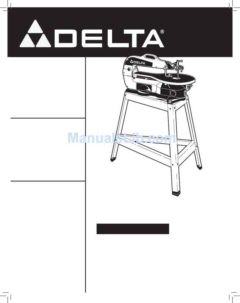
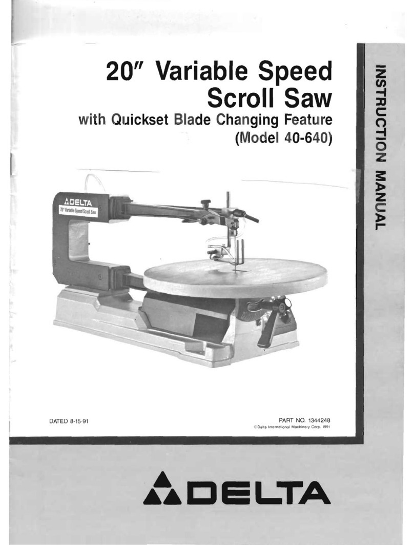
Delta 40-690 User manual

Sierra caladora de 508 mm
(20 pulg.) de velocidad
variable
Scie à découper à régulateur
de vitesse, 508 mm (20 po)
Instruction manual
Manuel d’utilisation
Manual de instrucciones
40-690
Français (13)
Español (24)
INSTRUCTIVO DE OPERACIÓN, CENTROS
DE SERVICIO Y PÓLIZA DE GARANTÍA.
LÉASE ESTE INSTRUCTIVO
ANTES DE USAR EL PRODUCTO.
www.deltaportercable.com
20" (508 mm) Variable
Speed Scroll Saw

2
TABLE OF CONTENTS
IMPORTANT SAFETY INSTRUCTIONS .....................2
SAFETY GUIDELINES - DEFINITIONS ......................2
GENERAL SAFETY RULES ........................................3
ADDITIONAL SPECIFIC SAFETY RULES ...................4
FUNCTIONAL DESCRIPTION ......................................6
CARTON CONTENTS....................................................6
ASSEMBLY ..................................................................7
OPERATION ................................................................9
TROUBLESHOOTING ...................................................11
MAINTENANCE .............................................................11
SERVICE.........................................................................11
ACCESSORIES..............................................................12
WARRANTY ...................................................................12
FRANÇAIS......................................................................13
ESPAÑOL .......................................................................24
IMPORTANT SAFETY INSTRUCTIONS
Read all warnings and operating instructions before using any tool or equipment. When
using tools or equipment, basic safety precautions should always be followed to reduce the risk of
personal injury. Improper operation, maintenance or modification of tools or equipment could result
in serious injury and property damage. There are certain applications for which tools and equipment
are designed. This product should NOT be modified and/or used for any application other than for which it was
designed.
If you have any questions relative to its application DO NOT use the product until you have written DELTA Machinery and
we have advised you. Contact us online at www.deltaportercable.com or by mail at End User Services, DELTA Machinery,
4825 Highway 45 North, Jackson, Tennessee 38305. In Canada,125 Mural St. Suite 300, Richmond Hill, ON, L4B 1M4)
Information regarding the safe and proper operation of this tool is available from the following sources:
www.powertoolinstitute.com
www.ansi.org
www.osha.gov
SAVE THESE INSTRUCTIONS!
SAFETY GUIDELINES - DEFINITIONS
will result in death or serious injury.
could result in death or serious injury.
may result in minor or moderate injury.
NOTICE
AVIS
AVISO
fr
sp
indicates a practice not related to personal injury which, if not avoided, may result in property
damage.
Some dust created by power sanding, sawing, grinding, drilling, and other construction activities
contains chemicals known to the State of California to cause cancer, birth defects or other reproductive harm.
Some examples of these chemicals are:
that are specially designed to filter out microscopic particles.

3
To reduce the risk of injury, read the instruction1. manual before operating the machine. Learning the
injury.
Wear eye and hearing protection and always use2. safety glasses. Everyday eyeglasses are not safety
glasses. Use certified safety equipment. Eye protection
equipment should comply with ANSI Z87.1 standards.
Hearing equipment should comply with ANSI S3.19
standards.
Wear proper apparel.3. Do not wear loose clothing, gloves,
neckties, rings, bracelets, or other jewelry which may get
caught in moving parts. Nonslip protective footwear is
long hair.
Do not use the machine in a dangerous environment.4. The use of power tools in damp or wet locations or in rain
can cause shock or electrocution. Keep your work area
fingers in danger.
Do not operate electric tools near flammable liquids5. or in gaseous or explosive atmospheres. Motors and
switches in these tools may spark and ignite fumes.
Maintain all tools and machines in peak condition. Keep tools sharp and clean for best and safest
performance. Follow instructions for lubricating and
machines can further damage the tool or machine and/or
cause injury.
Check for damaged parts.7. Before using the machine,
check for any damaged parts. Check for alignment of
moving parts, binding of moving parts, breakage of parts,
and any other conditions that may affect its operation.
A guard or any other part that is damaged should be
properly repaired or replaced with DELTA or factory
further damage to the machine and/or injury.
Keep the work area clean.8. Cluttered areas and benches
invite accidents.
Keep children and visitors away.9.
potentially dangerous environment. Children and visitors
can be injured.
Reduce the risk of unintentional starting.10. Make sure
that the switch is in the “OFF” position before plugging in
the power cord. In the event of a power failure, move the
switch to the “OFF
cause injury. Do not touch the plug’s metal prongs when
unplugging or plugging in the cord.
Use the guards.11. Check to see that all safety devices are
in place, secured, and working correctly to prevent injury.
Remove adjusting keys and wrenches before starting12. the machine. Tools, scrap pieces, and other debris can
be thrown at high speed, causing injury.
Use the right machine.13. Don’t force a machine or an
attachment to do a job for which it was not designed.
Damage to the machine and/or injury may result.
Use recommended accessories.14. The use of accessories
and attachments not recommended by DELTA may cause
damage to the machine or injury to the user.
Use the proper extension cord.15. Make sure your
will cause a drop in line voltage, resulting in loss of power
and overheating. See the Extension Cord Chart
gauge. The smaller the gauge number, the heavier the
cord.
Secure the workpiece. Use clamps or a vise to hold the
workpiece when practical. Loss of control of a workpiece
can cause injury.
Feed the workpiece against the direction of the17. rotation of the blade, cutter, or abrasive surface.
Feeding it from the other direction will cause the
workpiece to be thrown out at high speed.
Don’t force the workpiece on the machine.18. Damage to
the machine and/or injury may result.
Don’t overreach.19. Loss of balance can make you fall into
a working machine, causing injury.
Never stand on the machine.20. Injury could occur if the
tool tips, or if you accidentally contact the cutting tool.
Never leave the machine running unattended.21. Turn
the power off. Don’t leave the machine until it comes to a
complete stop. A child or visitor could be injured.
Turn the machine “22. OFF”, and disconnect the machine
from the power source before installing or removing
accessories, changing cutters, adjusting or changing
set-ups.
switch in the “OFF
cause injury.
Make your workshop childproof with padlocks, master23. switches, or by removing starter keys. The accidental
injury.
Stay alert, watch what you are doing, and use24. common sense. Do not use the machine when you
are tired or under the influence of drugs, alcohol, or
medication. A moment of inattention while operating
power tools may result in injury.
25. Use of this tool can generate and
disperse dust or other airborne particles, including
wood dust, crystalline silica dust and asbestos dust.
Direct particles away from face and body. Always operate
tool in well ventilated area and provide for proper dust
removal. Use dust collection system wherever possible.
lung disease), cancer, and death. Avoid breathing the
dust, and avoid prolonged contact with dust. Allowing
dust to get into your mouth or eyes, or lay on your skin
may promote absorption of harmful material. Always
use properly fitting NIOSH/OSHA approved respiratory
GENERAL SAFETY RULES
Failure to follow these rules could result in serious personal injury.

4
Failure to follow these rules could result in serious personal injury.
ADDITIONAL SPECIFIC SAFETY RULES
SAVE THESE INSTRUCTIONS.
Refer to them often and use them to instruct others.
replace following safety rules. Always remember that a careless
fraction of a second is sufficient to inflict severe injury.
qualified person if you are not thoroughly familiar with the
operation of this machine. Knowledge is safety.
assembled and installed according to the instructions. A
machine incorrectly assembled can cause serious injury.
cause machine to slide, walk or tip over.
cord when installing or removing the plug to or from the line
power source.
blade. The workpiece can be thrown, causing injury.
and type. Abnormal operations cause injuries.
move can cause injury.
instructions and remain in position during use. Also, be sure to
Loss of control of
a workpiece can cause injury.
adjustments when it is running. A moving blade underneath the
table can cause injury.
a hand to move into a saw blade or cutting tool. Do not place
fingers or hands in path of the saw blade.
table, be sure the saw is in the off position and blade has stopped
moving. A sudden slip could cause a hand to move into the blade
and injury could result.
feed or support devices for the operation planned. If left on the
finished, turn the machine “off”, disconnect the machine
from the power source, and clean the table/work area. Lock
Someone else might accidentally start the machine and
cause injury to themselves.
unless a suitable support is used. This type of workpiece can
pinch the blade before the cut is complete. Breaking blades
can cause injury.
moderate speed. Loss of control of a workpiece can cause injury.
uncompleted cut. Use appropriate speed for applications.
cut a curve that is too tight. Breaking blades can cause injury.
workpiece has a tendency to “roll” and can cause the blade
to bite. Breaking blades can cause injury.
com). Information is also available from the National Safety
and the U.S. Department of Labor OSHA 1910.213
Regulations.
NOT safety glasses. Also use face or dust mask if cutting
drilling, and other construction activities contains chemicals
known to the State of California to cause cancer, birth
these chemicals are:
masonry products, and
to these chemicals: work in a well ventilated area, and
work with approved safety equipment, such as those dust
masks that are specially designed to filter out microscopic
particles.
sawing, grinding, drilling, and other construction activities.
and water. Allowing dust to get into your mouth, eyes, or lay
on the skin may promote absorption of harmful chemicals.
cause serious and permanent respiratory or other injury. Always
use NIOSH/OSHA approved respiratory protection appropriate
duration of use, noise from this product may contribute to hearing
loss.

5
FIG. A FIG. B
GROUNDED
OUTLET BOX
CURRENT
CARRYING
PRONGS
GROUNDING BLADE
IS LONGEST OF THE 3 BLADES
GROUNDED OUTLET BOX
GROUNDING
MEANS
ADAPTER
POWER CONNECTIONS
A separate electrical circuit should be used for your machines. This circuit should not be less than #12 wire and should
be protected with a time delay fuse. NOTE: Time delay fuses should be marked “D” in Canada and “T” in the US. If
receptacle which will accept the machine’s plug. Before connecting the machine to the power line, make sure the
machine. All line connections should make good contact. Running on low voltage will damage the machine.
SHOCK HAZARD. Do not expose the machine to rain or operate the machine in damp locations.
MOTOR SPECIFICATIONS
sure the switch is in the “OFF” position.
GROUNDING INSTRUCTIONS
SHOCK HAZARD. This machine must be grounded while in use to protect the operator from electric
shock.
1. All grounded, cord-connected machines:
In the event of a malfunction or breakdown, grounding provides a path of least resistance for electric current to reduce
a grounding plug. The plug must be plugged into a matching outlet that is properly installed and grounded in accordance
with all local codes and ordinances.
live terminal.
Check with a qualified electrician or service personnel if the grounding instruction are not completely understood, or if in
doubt as to whether the machine is properly grounded.
accept the machine’s plug, as shown in Fig. A.
Repair or replace damaged or worn cord immediately.
2. Grounded, cord-connected machines intended for use on a supply circuit having a nominal rating less than
150 volts:
If the machine is intended for use on a circuit that has an outlet that looks like the one illustrated in Fig. A, the machine
will have a grounding plug that looks like the plug illustrated in Fig. A. A temporary adapter, which looks like the adapter
illustrated in Fig.
properly grounded outlet is not available. The temporary adapter should be used only until a properly grounded outlet
held in place with a metal screw.
NOTE: In Canada, the use of a temporary adapter is not permitted by the Canadian Electric Code.
SHOCK HAZARD. In all cases, make certain that the receptacle in question is properly grounded. If you
are not sure, have a qualified electrician check the receptacle.

EXTENSION CORDS
Use proper extension cords. Make
sure your extension cord is in good condition and is a
3-wire extension cord which has a 3-prong grounding
type plug and matching receptacle which will accept
the machine’s plug. When using an extension cord, be
sure to use one heavy enough to carry the current of
the machine. An undersized cord will cause a drop in
line voltage, resulting in loss of power and overheating.
Fig. C, shows the correct gauge to use depending on
the cord length. If in doubt, use the next heavier gauge.
The smaller the gauge number, the heavier the cord.
MINIMUM GAUGE EXTENSION CORD
Ampere
Rating Volts
Total
Length of
Cord in
Feet Gauge of Extension
Cord
0-6 120
up to
25 18 AWG
0-6 120 25-50 16 AWG
0-6 120 50-100 16 AWG
0-6 120 100-150 14 AWG
6-10 120
up to
25 18 AWG
6-10 120 25-50 16 AWG
6-10 120 50-100 14 AWG
6-10 120 100-150 12 AWG
10-12 120
up to
25 16 AWG
10-12 120 25-50 16 AWG
10-12 120 50-100 14 AWG
10-12 120 100-150 12 AWG
12-16 120
up to
25 14 AWG
12-16 120 25-50 12 AWG
12-16 120
FOREWORD
FUNCTIONAL DESCRIPTION
NOTICE: The manual cover illustrates the current production model. All other illustrations contained in the manual are
representative only and may not depict the actual labeling or accessories included. These are intended to illustrate
technique only.
CARTON CONTENTS
screws for work light)
1
4
6
2
3
7
8
9
10
11
5
Fig. C

7
ASSEMBLY
To reduce the risk of injury, turn unit off and disconnect it from power source before installing and
removing accessories, before adjusting or when making repairs.
ASSEMBLY TOOLS REQUIRED
ASSEMBLY TIME ESTIMATE
Assembly for this machine stand and light takes
SCROLL SAW STAND (40-691)
FOLLOW THESE RULES WHEN USING
THE STAND:
washers and nuts are provided for this purpose.
ASSEMBLY/ADJUSTMENT OF STAND (FIG. 1)
and nuts. Leave carriage bolts slightly loose until scroll
saw is secured to stand.
The rear leg of the stand is adjustable. Select the desired
height, ensure the rear leg is vertical, and firmly tighten
all four bolts shown.
NOTE:
assembled.
MOUNTING THE SAW TO STAND
onto the stand, keeping fingers and hands clear of the
stand.
through the underside of the stand and through the three
mounting holes in the scroll saw base. Secure the saw
to the stand by firmly tightening these three bolts and the
matching flat washer, lockwasher and nuts.
Tighten all carriage bolts on the stand after securing the
saw in place.
UNPACKING AND CLEANING
unpainted surfaces using a soft cloth moistened with mineral spirits, paint thinner or denatured alcohol.
Do not use highly volatile solvents such as gasoline, naphtha, acetone or lacquer thinner for cleaning your
machine.
FIG. 1
FIG. 2
MOUNTING
HOLES
ADJUSTABLE LEG
TOOL MOUNTING HOLES
FLOOR MOUNTING HOLES

8
FIG. 4
PIN
BACK OF TABLE
FIG. 5
FIG. 6
BLADE TENSION
LEVER
FIG. 7
HEX WRENCH
BOLTS
TABLE
BOTTOM
THUMBSCREW
TOP
THUMBSCREW
FIG. 3
BEVEL SCALE
TABLE
PIN
ASSEMBLING TABLE AND BLADE
ASSEMBLING TABLE
table and blade. To install the table, first insert the pin at
the back of the arm into the hole in the back of the table
against the arm and the pin is fully inserted in the table
securely attach the table to the bevel scale by tightening
the bolts shown in Figure 5.
INSTALLING THE BLADE
To reduce the risk of injury, turn unit off
and disconnect it from power source before installing
and removing accessories, before adjusting or when
making repairs.
The blade is held in place by the thumbscrew blade
clamps attached to the top and bottom arms of the scroll
Before installing a blade, make sure the blade tension
lever is moved fully to the right as shown in Figure 7.
hole in table, with the teeth facing toward the front of the
saw.
NOTE: Scroll saws cut on the downstroke, so it is
essential that teeth face forward and down.
Insert the blade into the bottom blade clamp and securely
the blade into the top blade clamp and securely tighten
Blade Tension Lever section of
this manual.)
blades.
BLADE TENSION LEVER
increase tension on the blade.
The proper degree of tension varies with different blade
tension on the blade.
As you become more accustomed to operating your
Remove the blade or release tension on the blade when

9
OPERATION
STARTING AND STOPPING SCROLL SAW
To reduce the risk of injury, make
sure that the switch is in the “OFF” position before
plugging cord into outlet. Do not touch the plug’s
metal prongs when unplugging or plugging in the
cord.
To turn the scroll saw on, press the front of the switch
provided in the switch for insertion of a padlock to lock
LOCKING SWITCH IN THE "OFF" POSITION
IMPORTANT:
switch should be locked
To reduce the risk of injury, in the event of
a power outage (such as a breaker or fuse trip), always
turn the tool "OFF" and unplug until the main power is
restored.
OPERATIONAL CONTROLS AND ADJUSTMENTS
FIG. 8
B
C
A
ATTACHING WORKLIGHT (40-692)
This scroll saw worklight is designed for use with your
other tool.
FOLLOW THESE RULES WHEN USING
THE INCLUDED LIGHT:
120 volt appliance bulb with a candelabra base.
Do not use a standard household bulb.
surface.
minutes before changing bulb.
scroll saw operation.
ASSEMBLY
Using the star wrench provided with the worklight,
the same screws, mount the worklight into the two holes
in the scroll saw housing, as shown.
Rotate the light switch clockwise to turn the light OFF and
ON.
FIG. 7A

10
MATERIAL HOLD-DOWN
rod up or down.
down before cutting.
NOTE:
functions as a barrier between fingers and blade.
AIR HOSE
to keep your work area free from dust and debris. Be sure
to position the air hose properly: it should blow saw dust
away from the operator.
SPEED CONTROL KNOB
400 to 1,750 strokes per minute. To operate the variable
the saw running.
To increase the speed, turn the knob clockwise. The
numbers on the speed control knob represent speed
speed.
Slower speeds are recommended for metals, plastics,
harder woods and very thin materials.
SAWING
Hold material firmly against table. Always feed material
toward the blade. Feed the workpiece fast enough to
allow the blade to cut, but do not force material into the
blade too quickly.
BEVELING
FIG. 10
FIG. 11
H
IJ
MACHINE USE
FIG. 9
D
E
F
G
NOTE:
the clearance around the lower thumbscrew. To facilitate
need to change places. On the setscrew side, sufficient
clearance is available.
FRETWORK
INSIDE CUTS
work. To make an inside cut:
1. Drill a pilot hole in your workpiece.
2. Make sure the blade tension lever is moved fully to
the right
3. Loosen the top thumbscrew blade clamp.
4. Leaving the blade held in place by the bottom blade
clamp, lift the top arm of the scroll saw, as shown in
Figure 11. Thread the saw blade through the pilot hole
in your workpiece and reattach the blade by tightening
the top thumbscrew.
5. Readjust the blade tension and begin the inside cut.
Alternately, you can loosen the bottom thumbscrew blade
clamp in step 3 above, and thread the blade through the
top of the workpiece.
NOTE: Do not lift saw by upper arm. Damage will occur.

11
FIG. 12
FUSE CAP
(INSERT THE TOOL
AND PRESS TO
RELEASE)
BRUSH
INSPECTION
CAPS
TROUBLESHOOTING
For assistance with your machine, visit our website at www.deltaportercable.com for a list of service centers or call the
MAINTENANCE
To reduce the risk of injury, turn unit off and disconnect it from power source before installing and
removing accessories, before adjusting or when making repairs.
KEEP MACHINE CLEAN
Wear certified safety equipment for eye, hearing and respiratory protection while using compressed air
FAILURE TO START
Should your machine fail to start, check to make sure the prongs on the cord plug are making good contact in the outlet.
Also, check for blown fuses or open circuit breakers in the line.
LUBRICATION & RUST PROTECTION
commercially available protective product designed for this purpose. Follow the manufacturer’s instructions for use and
safety.
lubricant and a can of degreaser. Apply the spray lubricant and polish the table surface with the scouring pad. Degrease
the table, then apply the protective product as described above.
OVERLOAD PROTECTOR
ped with a 3 amp overload
protection fuse. If your scroll saw becomes overloaded
and stops operating, turn off the scroll saw, check for a
BRUSHES
Inspect carbon brushes regularly by unplugging tool,
withdrawing the brush assembly. Keep brushes clean
and sliding freely in their guides. Always replace a used
brush in the same orientation in the holder as it was prior
it must be replaced. Use only identical DELTA brushes.
New brush assemblies are available at DELTA service
load) for 10 minutes before use to seat new brushes.
TABLE
Keep the table clean and free from oil, grease and pitch.
finish.
REPLACEMENT PARTS
Use only identical replacement parts. For a parts list or to order parts, visit our website at www.deltaportercableservicenet.com.
SERVICE

12
Since accessories other than those offered by DELTA have not been tested with this product, use of
such accessories could be hazardous. To reduce the risk of injury, only DELTA recommended accessories should be
used with this product.
A complete line of accessories is available from your DELTA Supplier, Porter-Cable • DELTA Factory Service Centers,
and DELTA Authorized Service Stations. Please visit our Web Site www.deltaportercable.com for a catalog or for the
name of your nearest supplier.
ACCESSORIES
FREE WARNING LABEL REPLACEMENT
If your warning labels become illegible or are missing, call
1-800-223-7278
for a free replacement.
TO REDUCE THE RISK OF ELECTRIC
SHOCK, DO NOT CONNECT TO AN
UNGROUNDED SUPPLY.
TO REDUCE THE RISK OF ELECTRIC
SHOCK, DO NOT CONNECT TO AN
UNGROUNDED SUPPLY.
PARA REDUCIR EL RIESGO DE
DESCARGA ELÉCTRICA, NO
CONECTE A UN SUMINISTRO SIN
CONEXIÓN A TIERRA.
POUR RÉDUIRE LE RISQUE DE CHOCS
ÉLECTRIQUES, NE PAS BRANCHER À
UNE SOURCE D’ALIMENTATION NON
MISE À LA TERRE.
TO REDUCE THE RISK OF
INJURY, USER MUST READ
TOOL INSTRUCTION MANUAL
BEFORE OPERATING
PRODUCT. FOR USE WITH
40-690 SCROLL SAW.
FASTEN TOOL TO STAND
BEFORE USE. TIGHTEN ALL
FASTENERS COMPLETELY
BEFORE USE. MAXIMUM
LOAD - 150 LBS (68 KG). DO
NOT CLIMB, SIT OR STAND
ON SAW STAND. DO NOT
USE STAND ON UNEVEN OR
UNSTABLE SURFACE.
PARA REDUCIR EL RIESGO DE
LESIONES, EL USUARIO DEBE LEER
EL MANUAL DE INSTRUCCIONES DE
LA HERRAMIENTA ANTES DE
OPERAR EL PRODUCTO. PARA USO
CON LA SIERRA CALADORA 40-690.
ASEGURE LA HERRAMIENTA A LA
BASE ANTES DEL USO. AJUSTE
COMPLETAMENTE TODOS LOS
SUJETADORES ANTES DEL USO.
CARGA MÁXIMA: (68 KG (150 LIBRAS).
NO SE SUBA, SIENTE NI PARE SOBRE
LA BASE DE LA SIERRA. NO UTILI
CE
LA BASE SOBRE UNA SUPERFICIE
DISPAREJA O INESTABLE.
AFIN DE RÉDUIRE LE RISQUE DE
BLESSURES, L’UTILISATEUR DOIT
LIRE LE MODE D’EMPLOI AVANT
D’UTILISER LE PRODUIT. UTILISER
AVEC LA SCIE À DÉCOUPER
40-690. FIXER L’OUTIL AU SOCLE
AVANT SON UTILISATION. BIEN
SERRER TOUTES LES ATTACHES
AVANT D’UTILISER L’OUTIL.
CHARGE MAXIMALE : 68 KG (150 LB).
NE PAS GRIMPER, S’ASSEOIR OU
SE TENIR DEBOUT SUR LE SOCLE
DE LA SCIE. NE PAS UTILISER LE
SOCLE SUR UNE SURFACE
INÉGALE OU INSTABLE.
MOD. 40-691
Scroll Saw Stand
Soporte de Sierra Caladora
Support de Scie à découper
DELT A Machinery, Jackson, TN 38305
Made in China / Hecho en China / Fabriquée en Chine
HOT SURFACE. KEEP AWAY
FROM CURTAINS AND
OTHER COMBUSTIBLE
MATERIALS. TO REDUCE
THE RISK OF FIRE, USE
MAX 25 WATT 120 VOLT,
TYPE S BULB. DO NOT
USE STANDARD
HOUSEHOLD BULB.
SURFACE CHAUDE. GARDER À
L’ÉCART DES RIDEAUX ET
D’AUTRES MATIÈRES
COMBUSTIBLES. POUR RÉDUIRE
LE RISQUE D’INCENDIE, UTILISER
UNE AMPOULE DE TYPE S, DE
25
W MAX. ET DE 120 V. NE
PAS UTILISER D’AMPOULE
DOMESTIQUE STANDARD.
SUPERFICIE CALIENTE.
MANTÉNGALA ALEJADA DE
CORTINAS Y OTROS MATERIALES
COMBUSTIBLES. PARA REDUCIR EL
RIESGO DE INCENDIO, UTILICE
UNA
BOMBILLA TIPO S DE 25
VATIOS MÁX. Y 120 VOLTIOS NO
UTILICE UNA BOMBILLA
ESTÁNDAR DE USO DOMÉSTICO.
SERVICE AND REPAIRS
All quality tools will eventually require servicing and/or replacement of parts. For information about DELTA Machinery, its
factory-owned branches, or to locate an Authorized Warranty Service Center, visit our website at www.deltaportercable.com
or call our End User Services at (800) 223-7278. All repairs made by our service centers are fully guaranteed against
defective material and workmanship. We cannot guarantee repairs made or attempted by others. By calling this number
you can also find answers to most frequently asked questions 24 hours/day.
You can also write to us for information at DELTA Machinery, 4825 Highway 45 North, Jackson, Tennessee 38305 -
Attention: End User Services. Be sure to include all of the information shown on the nameplate of your tool (model
number, type, serial number, date code, etc.)

13
Five Year Limited New Product Warranty
DELTA will repair or replace, at its expense and at its option, any new DELTA machine, machine part, or machine accessory which in normal
use has proven to be defective in workmanship or material, provided that the customer returns the product prepaid to a DELTA factory service
center or authorized service station with proof of purchase of the product within five years and provides DELTA with reasonable opportunity
to verify the alleged defect by inspection. For all refurbished DELTA product, the warranty period is 180 days. DELTA will not be responsible
for any asserted defect which has resulted from normal wear, misuse, abuse or repair or alteration made or specifically authorized by anyone
other than an authorized DELTA service facility or representative. Under no circumstances will DELTA be liable for incidental or consequential
damages resulting from defective products. Some states do not allow the exclusion or limitation of incidental or consequential damages, so
the above limitation or exclusion may not apply to you. This warranty is DELTA’s sole warranty and sets forth the customer’s exclusive remedy,
with respect to defective products; all other warranties, express or implied, whether of merchantability, fitness for purpose, or otherwise, are
expressly disclaimed by DELTA. For further detail of warranty coverage and warranty repair information, visit www.deltaportercable.com or call
(888) 848-5175. This warranty gives you specific legal rights and you may have other rights which vary in certain states or provinces.
WARRANTY
To register your tool for warranty service visit our website at www.deltaportercable.com.
LATIN AMERICA: This warranty does not apply to products sold in Latin America. For products sold in Latin America, see country specific
warranty information contained in the packaging, call the local company or see website for warranty information.

14
LES INSTRUCTIONS IMPORTANTES DE SURETE
Lire toutes instructions d'avertissements et opération avant d'utiliser n'importe quel
outil ou n'importe quel équipement. En utilisant les outils ou l'équipement, les précautions de sûreté
fondamentales toujours devraient être suivies pour réduire le risque de blessure personnelle. L'opération
déplacée, l'entretien ou la modification d'outils ou d'équipement ont pour résultat la blessure sérieux et
les dommages de propriété. Il y a de certaines applications pour lequel outils et l'équipement sont conçus. Ce produit NE
devrait être modifié en aucune façon et/ou utilisé pour aucune application autre que celle pour laquelle il a été conçu.
Dans Canada, 125 Mural
St. Suite 300, Richmond Hill, ON, L4B 1M4.
www.powertoolinstitute.com
www.ansi.org
U.S. Department of Labor regulations www.osha.gov
CONSERVER CES DIRECTIVES.
MESURES DE SÉCURITÉ - DÉFINITIONS
indique une situation dangereuse imminente qui, si elle n’est pas évitée, causera la mort ou des blessures
graves.
indique une situation potentiellement dangereuse qui, si elle n’est pas évitée, pourrait se solder par un décès
ou des blessures graves.
indique une situation potentiellement dangereuse qui, si elle n’est pas évitée pourrait se solder par des bles-
sures mineures ou modérées.
NOTICE
AVIS
AVISO
fr
sp
indique une pratique ne posant aucun risque de dommages corporels mais qui par contre, si rien n’est fait
pour l’éviter, pourrait poser des risques de dommages matériels.
Les scies, meules, ponceuses, perceuses ou autres outils de construction peuvent produire des
poussières contenant des produits chimiques reconnus par l’État californien pour causer cancers, malformations
congénitales ou être nocifs au système reproducteur. Parmi ces produits chimiques, on retrouve :

15
Pour sa sécurité personnelle, lire la notice d’utilisation,1. avant de mettre la machine. En marche, et pour aussi
apprendre l’application et les limites de la machine ainsi
que les risques qui lui sont particuliers ainsi, les possibilités
d’accident et de blessures seront beaucoup réduites.
Portez des dispositifs de protection des yeux et de l'ouïe.2. Utilisez toujours des lunettes de sécurité. Des lunettes
ordinaires ne constituent pas des lunettes de sécurité.
ANSI Z87.1. Les dispositifs de protection de
ANSI S3.19.
Porter une tenue appropriée.3.
des blessures.
Ne pas utiliser la machine dans un environnement4. dangereux. L’utilisation d’outils électriques dans des
Ne pas utiliser d’outils électriques à proximité de5. liquides inflammables ou dans une atmosphère gazeuse
ou explosive. Les moteurs et interrupteurs des outils
pourraient provoquer des étincelles et enflammer des
vapeurs.
Garder les outils et les machines en parfait état.
et changer les accessoires. Les outils et les machines mal
des blessures.
Inspecter les pièces pour déceler tout dommage.7. Avant
d’utiliser la machine, la vérifier pour voir s’il n’y a pas de
blessures.
Garder l’aire de travail propre.8.
encombrés favorisent les accidents.
Garder les enfants et les visiteurs à distance.9. L’atelier
visiteurs peuvent se blesser.
Éviter le démarrage accidentel.10. S’assurer que l’interrupteur
est sur « OFFARRÊT) avant de brancher le cordon. En
« OFFARRÊT
des blessures.
Utiliser les dispositifs protecteurs11. .
bon état de marche pour éviter les blessures.
Enlever les clés de réglage et celles de serrage avant de12. mettre la machine en marche. Les outils, les chutes et les
Utiliser la bonne machine.13. Ne pas forcer la machine ou
s’ensuivre.
Utiliser les accessoires recommandés.14. L’utilisation
d’accessoires non recommandés par DELTA peut
endommager la machine et blesser l’utilisateur.
RÈGLES DE SÉCURITÉ GÉNÉRALES
L’inobservation de ces règles peut conduire à des blessures graves.
Utiliser le cordon prolongateur approprié.15. S’assurer
que le cordon prolongateur est en bon état. Lorsqu’un
perte de tension d’où une perte de puissance et surchauffe.
Tableau sur Les Cordons prolongateurs pour
obtenir le calibre approprié selon la longueur du cordon
et l’ampérage de la machine. S’il y a un doute, utiliser un
le fil est gros.
Fixer la pièce.
causer des dommages.
Avancer la pièce dans le sens contraire à la rotation17. de la lame, de la fraise ou de la surface abrasive.
18. Ne pas forcer la machine en avançant la pièce trop vite.
Des dommages et/ou des blessures peuvent s’ensuivre.
Ne pas se pencher au-dessus de la machine.19. Une perte
marche et causer des blessures.
Ne jamais monter sur la machine.20. On peut se blesser
gravement si la machine bascule ou si l’on touche
accidentellement son outil tranchant.
Ne jamais laisser la machine en marche sans21. surveillance. Couper le courant. Ne pas quitter la
enfant ou un visiteur pourrait se blesser.
Mettre la machine à «22. OFF » (ARRÊT) et la débrancher
avant d’installer ou d’enlever des accessoires, changer
les coupeurs, d’ajuster ou de changer des montages.
de début en position « OFFARRÊT). Un démarrage
Mettre l’atelier à l’abri des enfants au moyen de23. cadenas, d’interrupteurs principaux ou en enlevant
les boutons des dispositifs de mise en marche. Le
démarrage accidentel de la machine par un enfant ou un
Rester vigilant, attentif, et faire preuve de bon sens.24. Ne
pas utiliser la machine lorsque l’on est fatigué ou sous
l’influence de drogues, d’alcool ou de médicaments. Un
instant d’inattention lors de l’utilisation d’outils électriques
25. L'utilisation de cet outil peut
produire et disperser de la poussière ou d'autres
particules en suspension dans l'air, telles que la sciure
de bois, la poussière de silicium cristallin et la poussière
d'amiante.
de santé graves et permanents, respiratoires ou autres,
de protection respiratoire homologués par niosh/osha,

RÈGLES SPÉCIFIQUES ADDITIONNELLES DE SÛRETÉ
L’inobservation de ces règles peut conduire à des blessures graves.
CONSERVER CES DIRECTIVES
Les consulter souvent et les utiliser pour donner des directives aux autres.
fréquente de la scie) remplacer les consignes de sécurité
suivantes. Se rappeler qu’il suffit d’une fraction de seconde
l’utilisation de cette machine. Le savoir est source de sécurité.
Une machine incorrectement assemblée pose des risques de
dommages corporels graves.
le banc ou l’établi au sol. Les vibrations pourraient faire glisser,
bouger la machine ou la renverser.
débranchement de la fiche.
des dommages corporels.
pas verrouillées et que la lame n’est pas sur la tension adéquate.
utilisation anormale pose des risques de dommages corporels.
en toute sécurité. Lorsque les mains sont trop proches de la
corporels.
marche.
travailler pourrait occasionner des dommages corporels.
pendant le fonctionnement de l’outil. La lame en mouvement
sous la table pose des risques de dommages corporels.
levage.
une chute soudaine et les mettre en contact avec la lame ou
l’organe de coupe. Ne pas mettre les doigts ou les mains sur le
chemin de la lame.
Une chute soudaine pourrait provoquer un contact involontaire
des mains avec la lame et poser des risques de dommages
corporels
l’opération en cours. Laissés sur la table, ces débris pourraient
Un tiers pourrait accidentellement faire démarrer la machine et se
blesser.
coupe. Une lame qui se casse pose des risques de dommages
corporels.
en cours de coupe. Utiliser la vitesse appropriée au travail en
cours.
de « dégagement ». Ne jamais effectuer de courbes trop
serrées. Une lame qui se casse pose des risques de dommages
corporels.
causer le grippage de la lame. Une lame qui se casse pose des
risques de dommages corporels.
chimique.
avoir comme conséquence l’absorption de produits chimiques
respiratoire. Utiliser systématiquement un appareil respiratoire
particules dans le sens opposé au visage et au corps.
Sous certaines conditions et suivant la longueur d’utilisation, le
l’acuité auditive.

17
2. Machines avec cordon mis à la terre prévues pour uneutilisation sur une alimentation nominale inférieure à 150 volts:
REMARQUE: Au Canada, le Code canadien de l’électriciténe permet pas l’emploi d’un adaptateur temporaire.
RISQUES DE CHOCS ÉLECTRIQUES. Dans tous les cas, s'assurer quela prise en question est bien mise à
la terre. Dans le doute, demander à un électricien compétentde vérifier la prise.
RACCORDEMENTS ÉLECTRIQUES
protégé par un fusible temporisé. REMARQUE :
machine.
RISQUES DE CHOCS ÉLECTRIQUES. Ne pas exposer la machine à la pluie, et ne pas l’utiliser dans des
endroits humides.
FIG. A FIG. B
BOÎTE À PRISES MISE À LA TERRE
BROCHES
CONDUCTRICESDE
COURANT
LA BROCHE DE MISE
ÀLA TERRE EST LA PLUS
LONGUEDES TROIS
OREILLE DE MISEÀ LA
TERRE
ADAPTATEUR
BOÎTE À PRISES MISE À LA TERRE
1. Toutes les machines avec cordon mis à la terre:
un électricien compétent.
Réparer ou remplacer sans délai tout cordon endommagé ouusé.
INSTRUCTIONS DE MISE À LA TERRE
RISQUES DE CHOCS ÉLECTRIQUES. Cette machine doit être mise à la terre pendant son emploi, afin de
protégerl’utilisateur des décharges électriques
SPÉCIFICATIONS DU MOTEUR

18
CORDON DE RALLONGE
Employez les cordes appropriées
de prolongation. S'assurent votre corde de prolongation est
en bon état. En utilisant une corde de prolongation, soyez
sûr d'employer un assez lourd pour porter le courant de la
machine. Une corde trop petite causera une baisse dans la
tension secteur, ayant pour résultat la perte de puissance
et de surchauffe. Fig. C, expositions la mesure correcte
à employer selon la longueur de corde. En cas de doute,
utilisez la prochaine mesure plus lourde. Plus le nombre de
mesure est petit, plus la corde est lourde.
Fig. C
MESUR MINIMUM DE CORDE D’EXTENSION
Estimation
pere Volts
Longueur
Totale De
Corde En
Pieds Mesure De Corde D’Am
D’Extension
0-6 120
up to
25 18 AWG
0-6 120 25-50 16 AWG
0-6 120 50-100 16 AWG
0-6 120 100-150 14 AWG
6-10 120
up to
25 18 AWG
6-10 120 25-50 16 AWG
6-10 120 50-100 14 AWG
6-10 120 100-150 12 AWG
10-12 120
up to
25 16 AWG
10-12 120 25-50 16 AWG
10-12 120 50-100 14 AWG
10-12 120 100-150 12 AWG
12-16 120
up to
25 14 AWG
12-16 120 25-50 12 AWG
12-16 120
DESCRIPTION FONCTIONNELLE
AVANT-PROPOS
gauche.
REMARQUE :
Ces illustrations ont uniquement pour but d’illustrer la technique.
2.
lampe de travail)
16
2
7
8
9
10
11
5
CONTENUS DE BOITE
4
3

19
ASSEMBLAGE
OUTILS NÉCESSAIRES POUR L’ASSEMBLEE
Clé ouverte de 1/2 po pour la quincaillerie de l’établi et de la
L'ESTIMATION DE TEMPS D'ASSEMBLEE
SUPPORT POUR SCIE À DÉCOUPER (40-691)
SUIVEZ CES RÈGLES EN EMPLOYANT
LE STAND
instables.
support.
MONTAGE ET RÉGLAGE DE SUPPORT (FIG. 1)
serrer les quatre boulons illustrés.
NOTE :
MONTAGE DU SCIE AU SUPPORT
mains du support.
sous le support dans les trois trous de montage de
la scie au support en serrant fermement les trois boulons.
au support.
en place.
Pour réduire le risque de blessures corporelles graves, éteindre l’outil et le débrancher avant d’installer
et de retirer tout accessoire, avant d'ajuster ou de modifier les réglages ou lors de réparations. Un démarrage accidentel peut
provoquer des blessures.
DÉSEMBALLAGE ET NETTOYAGE
N’utiliser pas de solvants hautement volatils tel l’essence, le naphte, l’acétone ou du diluant à laque
pour nettoyer.
FIG. 1
FIG. 2
PIED ADJUSTABLE
ORIFICE POUR DE MONTAGE
ORIFICE MONTAGE DU PLANCHER
TROUS DE
MONTAGE

20
FIG. 4
TIGE
ARRIÈRE DE LA TABLE
FIG. 5 FIG. 6
LEVIER DE TENSION
DE LA LAME
FIG. 7
CLÉ
HEXAGONALE
BOULONS
TABLE
VIS À
OREILLES
INFÉRIEURE
FIG. 3
ÉCHELLE DE
BISEAUX
TABLE
TIGE
ASSEMBLEZ LE TABLE ET LA LAME
ASSEMBLAGE LE TABLEAU
La scie est complètement assemblée à l’exception de la table et
de la lame. Pour installer la table, il faut d’abord insérer la tige
qui se trouve à l’arrière du bras dans le trou qui se trouve à
l’arrière de la table (fig. 3). Pousser la table jusqu’à ce que sa
surface arrière repose contre le bras et que la tige est
complètement insérée dans la table (fig. 4).
Se servir de la clé hexagonale fournie dans l’emballage pour
fixer sûrement la table à l’échelle de biseaux en serrant les
boulons illustrés à la figure 5.
INSTALLATION DE LA LAME
Pour réduire le risque de blessures
corporelles graves, éteindre l’outil et le débrancher avant
d’installer et de retirer tout accessoire, avant d'ajuster ou de
modifier les réglages ou lors de réparations. Un démarrage
accidentel peut provoquer des blessures.
Avant d’installer la lame, s’assurer que le levier de tension de la
le trou de la table, en faisant pointer les dents de la lame vers
l’avant de la scie.
NOTE :
descendante, il est donc essentiel de faire pointer les dents de
la lame vers l’avant et vers le bas.
Bien régler la tension de la lame avant de se servir de la scie
sulter Levier De Tension De La Lame du
présent guide.)
LEVIER DE TENSION DE LA LAME
Déplacer le levier de tension de la lame (fig. 7) vers la gauche
afin d’augmenter la tension de la lame.
La tension appropriée dépend de la dimension de la lame. Les
lames fines nécessitent plus de tension; les plus grosses, moins.
Lorsque les lames cassent souvent, diminuer la tension de la
lame.
Lorsqu’on connaît bien le fonctionnement de la scie à découper,
il est plus facile de régler précisément la tension de la lame.
Pratiquer sur des échantillons lorsque c’est possible.
Retirer la lame ou dégager la tension de la lame lorsqu’on ne se
sert pas de la lame pendant de longues périodes.
VIS À OREILLES
SUPÉRIEURE
Table of contents
Languages:
Other Delta Saw manuals

Delta
Delta 96-107 User manual

Delta
Delta UNISAW 36-812 User manual

Delta
Delta ShopMaster BS100 User manual

Delta
Delta 28-293 User manual

Delta
Delta ShopMaster BS150LS User manual

Delta
Delta 26-2312 User manual

Delta
Delta 36-260 User manual

Delta
Delta UniSaw 36-L31 User manual

Delta
Delta 36-477 User manual

Delta
Delta 36-725 User manual

Delta
Delta 28-306 User manual

Delta
Delta 15'' scroll saw User guide

Delta
Delta 36-650 User manual

Delta
Delta RS830 User manual

Delta
Delta N028314 User manual

Delta
Delta 36-075 User manual

Delta
Delta 33-891 User manual

Delta
Delta 36-725 T2 User manual

Delta
Delta ShopMaster TS300 User manual

Delta
Delta 33-990 User manual