Warning
3This instruction sheet only provides information on electrical specifications, general specifications, installation and
wiring.
3The components and the IC on the circuit board can be easily damaged by static electricity; therefore DO NOT touch
them before precautions against static electricity are done. To prevent the danger and damage from occurring, people
who are not maintenance staff should not operate or accidentally hit the body of the DVS series switch. Besides, DO
NOT touch any terminal when the power is switched on.
3This product is equipped with Class 1 LASER/LED components. DO NOT stare directly at the LASER/LED beam to
avoid serious injury to your eyes.
3Please read this instruction sheet thoroughly, and follow the instructions to prevent the damage to the device or injury
to the staff.
X Introduction
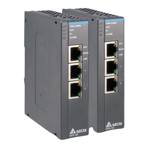
Thank you for purchasing the DVS Managed Industrial Ethernet Switches. The DVS series switches are
equipped with the intelligent alarm, digital input function, and allow the wide range of operating temperature (-40
to 75oC). The DVS series switches are designed to support the application in any rugged environment and
comply with UL, CE and FCC standards.
YFunctions
1. 10/100Base-T(X) (RJ45), 10/100/1000Base-T (RJ45), 100/1000Base-SFP Fiber
2. IEEE 802.3/802.3u/802.3ab/802.3x/802.3z
3. Auto-negotiation speed
4. Auto-MDI/MDI-X
ZPackage Checklist
1. One Delta DVS Managed Ethernet Switch
2. Protective Caps for unused RJ45 ports
3. Wall mounting Plate x1
4. USB Type A to Type B console cable x1
5. User manual and software CD
6. Instruction Sheet
ENGLISH
[Installation
DIN-Rail Mounting
Mounting
Step 1: Hook the upper end of the DIN clip of the
DVS series switch on the DIN-Rail.
Step 2: Lightly push the DVS series switch toward
the DIN-Rail until they contact each other
closely.
Removal
Step 1: Insert the flat-blade screwdriver into the DIN
clip and pull the DIN clip downward.
Step 2: Pull the DVS series switch, and you can
remove it from the DIN-Rail.
Wall Mounting
Step 1: Insert the wall mounting bracket into the slot on the rear panel of the DVS series switch, and tighten the
screw on it, as shown in the diagram below.
Step 2: Place the wall mounting bracket in an appropriate position, and tighten the two screws on the bracket
and the DIN clip.
\Wiring the Redundant Power Input
The DVS series switches are equipped with one to two sets of DC input (PWR1 / PWR2). Both sets of DC input
can be connected to a wide range of power sources (12 to 48VDC). If one power source fails, the other live
source can work as a backup to ensure that the machine operates normally.
Step 1: Insert the negative and positive DC wires into the terminal block, and make sure that the positive DC
wire is connected to V1+ or V2+, and that the negative DC wire is connected to 0V.
Step 2: To prevent the loose DC wires, tighten the wire clamp screws on the terminal block connector with the
flat-blade screwdriver.
NOTE: Please use copper wire 60/75oC, conductor 16 to 24 AWG; screw up at torque 2.2kgf-cm(1.91 in-lbs)
Step 3: Insert the plastic terminal block connector into the terminal block receptor on the DVS series switch.
NOTE: Grounding the ground terminal on the DVS series switch can avoid the noise effect due to the
electromagnetic interference (EMI).
Please use Class 2 power sources.
The devices are designed for operation with a LPS power supply of “12 to 48VDC, 1A power rating”
in accordance with EN 60950-1 ed.2.
The devices is intended to be operated under altitude up to 10,000ft(3048m), the DC power supply
source comply with the requirement of 10,000ft(3048m) of clearance is multiplied by the altitude
correction factor(1.15), specified in table A.2 of IEC 60664-1, 1992+A1:2000.
]Wiring the Alarm Contact
The DVS series switches are equipped with one to two sets of alarm (Alarm1 / Alarm2).The alarm contact is a
dry relay. If one of the two power sources fails, one of digital input is triggered or the communication is
interrupted, the contact will turns from an “OPEN”circuit to a “CLOSED”circuit. The relay can be connected to
a 5A/24VDC power source.
^Wiring the Digital Input
The DVS series switches are equipped with one to two sets of digital input (DI1 / DI2). If the power source
between 0 to 5V, the state of DI is OFF. If the power source between 11 to 30V, the state of DI is ON. The
maximum input current is 6mA.
The electrical circuit of DI1 and DI2 are independent, so you don’t need to care about NPN type or
PNP type of DI. If the electrodes positive and electrodes negative of DI has been reversed when you
plug the cable, DI still can work properly.
_LED Indicators
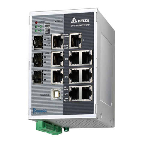
DVS-108W02-2SFP / 109W02-1GE / 110W02-3SFP
LED Color Status Description
ON The communication is interrupted, there is a power failure, or alarm
event which has been configured happened.
ALARM Red
OFF The communication is not interrupted, there is no power failure, or alarm
event which has been configured doesn’t happen.
ON The power is supplied normally.
PWR1/ PWR2 Green OFF The power is not supplied.
ON The DI is triggered.
DI1/DI2 Green
OFF The DI is not triggered.
ON The port is connected at a speed of 10 or 100 Mbps.10/100M
(RJ45) Orange OFF The port is disconnected.
Green ON The port is connected at a speed of 1000 Mbps.
Orange ON The port is connected at a speed of 10 or 100 Mbps.
10/100/1000M
(RJ45) OFF The port is disconnected.
Green ON The port is connected at a speed of 1000 Mbps.
Orange ON The port is connected at a speed of 100 Mbps.
100/1000M
(SFP Fiber)
OFF The port is disconnected.
LED Color Status Description
ON The Network communication connection has been established.
Blinking The data is being transmitted.
LINK/ACT Green
OFF The Network communication connection has not been established.
ON As a master of ONE RING, or a forwarding path of Coupling Ring.
Blinking Any node disconnection is occurred in ONE RING or Coupling Ring.
R.M/CPLG.R Yellow
OFF A slave of ONE RING, or ONE RING or Coupling Ring is not available.
ON As a head or a tail of ONE CHAIN.
Blinking As a head or a tail of ONE CHAIN, any node disconnection is occurred.
C.HD/C.TL Green
OFF ONE CHAIN is not available.
`Ethernet Interface
10/100Base-T(X), 10/100/1000Base-T Connection
The 10/100Base-T(X) or 10/100/1000Base-T ports of the DVS series switches are used to connect to Ethernet.
RJ45 ports support MDI (NIC–type) and MDI-X (HUB/Switch-type) modes, the pin definition of the Ethernet
cable is as follows.
10/100Base-T(X) 1000Base-T
PIN MDI Mode MDI-X Mode MDI/MDI-X Mode
1 Tx+ Rx+ TP0+
2 Tx- Rx- TP0-
3 Rx+ Tx+ TP1+
4 n.c. n.c. TP2+
5 n.c. n.c. TP2-
6 Rx- Tx- TP1-
7 n.c. n.c. TP3+
8 n.c. n.c. TP3-
100/1000Base-SFP Fiber Connection
Each SFP module has TX and RX interface, make sure the fiber connect TX interface to RX interface between
two SFP modules.
aMechanical Characteristics
DVS-108W02-2SFP DVS-109W02-1GE DVS-110W02-3SFP
Case IP40 Aluminum metal case
Dimension(mm) 145.3 (H) x 75(W) x 108.2(D)
Weight(g) 520 500 564
For more information about the product, please visit http://www.deltaww.com
TX
RX
RX
TX
㮦⿍ᵉ曃
3㭋⭰壄㈲ⅱ⏑㎷ᾂ曢㰊奶㠣˚刓奶㠣˚⭰壄⎱愴䷁˛
3曢巖㝦䙫曝ờ凮 IC 㗺⎾权曢䠛⣅Ə㜑⁁⥤昙权曢㎑㖤∴媲⋦䔏㈲姟㑟˛昙㭉杅䶔孞ạⓈ㒴ὃㇽヶ⣽塄㒱㜓
檻Ə怇ㇷ⍘暑凮㏴⣅Ə媲⋦✏曢㘩姟㑟ỢἼ䫖⬷˛
3㜓䔉⒨⏖僤ⅎ⻡ Class 1 LASER/LED ℰ㔝䙣♏Ə媲⋦䛛好ℰ乽⟇⏊Ə␍∮⯮⯴䜣䝂怇ㇷ⚛憴䙫⮚˛
3媲⋀⾬ẻ䴗斘孧㜓⭰壄媑㗵Əḍᾄ䅎媑㗵㋮䤡怙堳㒴ὃƏỌℴ怇ㇷ䔉⒨⎾㏴Əㇽ⯵凛ạⓈ⎾˛
X 䏠⍿䫟ᶉ
ㄆ嬄わὦ䔏⏗总DVSⷌ㥔䴁䶙䮈❲Ṁ⤑䶙巖ẋ㏂♏˛DVS䳢⇾㘖⯯䂡ㆰ䔏㖣⏫⚛勂䒗⡪㈧娔姯Ḳ姊㱡㖠㠯˛⅞
₀曢㹷㔬暃, 㕟ἴ弟⅌, 态姱㖞䷁孍⠘弟⇡⎱-40 ~ 75oC⯓㺒ⷌὃ㨀㹽˛ℑ嵱ⷌ嗄㉧堺Ə态怵UL˚CE凮FCC䬰ⷌ
㥔⭰奶婴嬰˛
Y⅝侻䄷儰
1. 10/100Base-T(X) (RJ45)˚10/100/1000Base-T (RJ45)˚100/1000Base-SFP ℰ乽
2. IEEE 802.3/802.3u/802.3ab/802.3x/802.3z
3. 凑⊼ₚ弟怆䍮⁜㸓
4. MDI/MDI-X 凑⊼巚䷁⁜㸓
Z䏠⍿⇃垛
1. ⏗总 DVS ⷌ㥔䴁䶙䮈❲Ṁ⤑䶙巖ẋ㏂♏ x1
2. RJ45 ῄ孞咲
3. ⢨㎂憸ⱓ愴ờ
4. USB A ⅓弰 B⅓㎎∝䷁ x1
5. ὦ䔏㈲ⅱ⎱䔉⒨ℰ䢆
6. ⭰壄媑㗵㛟
丨檻Ḕ㕮
[⩇垛㑷ⷍ
庳怺⭰壄
⭰壄
㭌橆Ɲ⯮ DVS 傳⽳䙫憸ⱓ⭰壄愴ờ㉊ἶ
DIN-Rail
㭌橆ṳƝ⯮ DVS ⏸ⅎ㎏Ə䛛∗憸ⱓ⼯䰎⤥凮
DIN-Rail ⭳⅏䶱⏯
⍟
㭌橆Ɲ⯮⬾嵞⬷㎹⅌憸ⱓ⼯䰎⤥䙫㴅⬻ḍ⏸
㊰
㭌橆ṳƝ㊰嵞 DVS 惏⍚⏖柭⋉⎽⇡
⢨㎂⭰壄
㭌橆Ɲ⯮昫忨䙫⢨㎂憸ⱓ愴ờ㎹⅌ DVS ⽳䙫⇠㧤Əḍ䔏⌨⬾垡䵙嵞⬷⯮憸ⱓ愴ờ捽䶱㖣 DVS
㭌橆ṳƝ䵺䔘 DVS ⽳憸ⱓ愴ờ䙫⅐ῲ垡䵙⬻Ə⯮ DVS 捽䶱㖣わ㈧曧奨䙫ἴ何˛
\ὗ㊲ⷍ方㵎巶‣
DVSⅎ⻡∗⅐䴫12 ~ 48VDC䛛㴨曢弟⅌ƋPWR1/PWR2ƌ˛䕝⅝Ḕ䴫曢㹷㔬暃㘩Ə⏍䴫曢㹷⏖Ọ榓╆
⊼Ə䢡ῄ㩆♏㭊⸟怲ὃ˛
㭌橆Ɲ⯮䫖⬷⺎⅓栔⾅ DVS ⎽Əḍ⯮ DC 䛛㴨曢曢㹷䷁㎹⅌䫖⬷⺎⅓栔Əḍ䢡婴㭊㥜㎌⅌ V1+ㇽV2+俳岇
㥜㎌⅌ 0V
㭌橆ṳƝ∐䔏⯶⬾垡䵙嵞⬷⯮曢㹷䷁捽䶱㖣䫖⬷⺎⅓栔
娢Ɲ媲ὦ䔏60/75oC, ⯵檻䷁⽸䂡16-24AWGḲ扬䷁ƞ⅝捽垡䵙Ḳ㉔⊂䂡2.2kgf-cmƋ1.91 in-lbsƌ
5018063300
