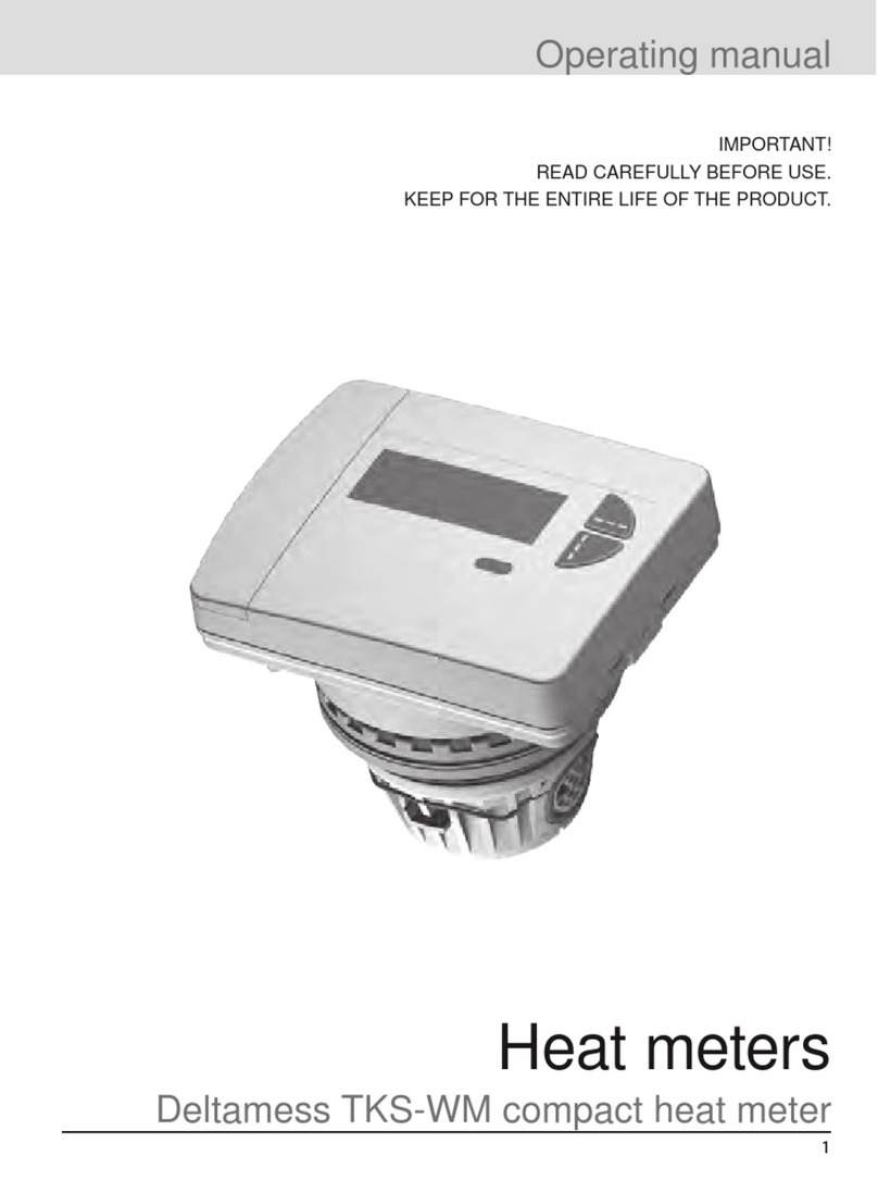
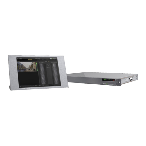
Deltamess TKS-WM User manual

1
Installation instructions
For competent personnel only
Deltamess TKS-WM compact heat meter
Heat meters
IMPORTANT!
READ CAREFULLY BEFORE USE.
KEEP FOR THE ENTIRE PRODUCT LIFE.
30186-4 Kompakt-WMZ TKS-WM Installationsanleitung_031215_EN.indd 1 03.12.2015 15:14:52

2
Scope of delivery
Heat meter (calculator with measuring capsule incl. installed temperature
sensor)
Blister pot (measuring capsule protective cap)
Installation instructions
Operating manual with CE-Declaration of conformity with disposal instructions
Use information for existing pockets (for Germany only)
Accessory kit with two security seals
Temperature sensor for ball valve / tee (O-ring red) preassembled
- Consisting of: 1 x TF bolt (0352), 1 x extension ring (1520)
- 1 x O-ring black (1109) 1 x O-ring green (0787), 1 O-ring red V-pipe (0759)
Please keep the documentation for the entire life.
30186-4 Kompakt-WMZ TKS-WM Installationsanleitung_031215_EN.indd 2 03.12.2015 15:20:52
Temperature sensor for body TKS (O-ring blue) preassembled
- Consisting of: 1 x TF bolt (0352), 1 x extension ring (1520) ,
- 1 x O-ring black (1109), 1 x O-ring green (0787), 1 O-ring blue R-pipe (0760)

3
Contents
Scope of delivery.....................................................................................................2
Contents...................................................................................................................3
Safety and warranty ................................................................................................5
Important note ................................................................................................................5
Lithium battery safety.............................................................................................6
Safety instructions for lithium batteries .............................................................................6
Technical data..........................................................................................................7
Standards and directives...................................................................................................7
Calculator..........................................................................................................................7
Connection sizes and dimensions.....................................................................................8
Temperature sensor..........................................................................................................8
Calculator - volume measuring part connection cable......................................................8
Dimensioned drawings...........................................................................................9
TKS-WM interface DM1....................................................................................................9
TKS-WM temperature sensor for housing.........................................................................9
Overall TKS-WM lengths.................................................................................................10
TKS-WM housing sensor installation..............................................................................12
Symbols and warnings .........................................................................................14
Installation positions.............................................................................................15
Installation variants - without pocket..................................................................16
Housing without shut-off valves ......................................................................................16
Housing with shut-off valves ...........................................................................................16
Installation variants - with pocket........................................................................17
Housing without shut-off valves ......................................................................................17
Identifying the EAT..........................................................................................................17
Prepare for installation - without pocket.............................................................18
- for new installation........................................................................................................18
- for instrument replacement...........................................................................................18
Prepare for installation - with pocket ..................................................................19
- for new installation........................................................................................................19
- for instrument replacement...........................................................................................19
Installing the heat meter (heat meter replacement part available) ...................20
Preparing for installation .................................................................................................20
Installing the housing ......................................................................................................20
Insert the measuring capsule, note the flow direction.....................................................21
Fixing the measuring capsule .........................................................................................22
30186-4 Kompakt-WMZ TKS-WM Installationsanleitung_031215_EN.indd 3 03.12.2015 15:22:52

4
Contents
Installing the temperature sensor - without pocket (ball valve)........................23
Temperature sensor - diameter 5.2 mm..........................................................................23
Installing the temperature sensor - with pocket.................................................24
Wall-mounted installation with removable calculator........................................25
Check the installation ...........................................................................................26
Open the shut-offs...........................................................................................................26
Check for leaks and check flow direction........................................................................26
Sealing the instrument..........................................................................................27
Sealing the flow sensor...................................................................................................27
Sealing the temperature sensor in the ball valve............................................................27
Sealing the temperature sensor in the pocket.................................................................28
Note the meter readings .......................................................................................28
Instrument elements .............................................................................................29
Controls and interfaces...................................................................................................29
Status displays................................................................................................................29
Display....................................................................................................................30
Special operating states..................................................................................................30
Error messages...............................................................................................................30
Key assignments...................................................................................................31
Key assignment in default mode.....................................................................................31
Key assignment in programming mode...........................................................................31
Putting into use .....................................................................................................32
Activate programming mode...........................................................................................32
Example: Programming the reference date ....................................................................32
Example: Activating / deactivating levels........................................................................33
Example: Switch the check number display on / off (postcard readout) .........................33
Example: Change the dimensional unit (kWh <−> MWh or MJ <−> GJ).......................34
Installation suggestions .......................................................................................35
Checklist.................................................................................................................36
Before the installation......................................................................................................36
Following installation.......................................................................................................37
After putting into use.......................................................................................................37
Notes on heat meter add-on modules ................................................................38
Use of combined heat/cooling meters with add-on module.....................................38
WFZ16x.Ox - add-on radio module.................................................................................38
R99/0005-02 - add-on M-Bus module.............................................................................39
30186-4 Kompakt-WMZ TKS-WM Installationsanleitung_031215_EN.indd 4 03.12.2015 15:29:52
Temperature sensor mouting ..........................................................................................23

5
This product must be installed properly and in accordance with the specied
installation guidelines and may therefore only be installed by trained, qualied
competent personnel.
Intended use
Heat meters are used for central recording of heating energy consumption. Heat
meters are intended for this use only.
Improper use
Any use other than the use described above or any changes made to the instru-
ment constitutes improper use. Enquiries concerning other uses and modica-
tions must be made in writing beforehand and must be especially approved.
Warranty and guarantee
Warranty and guarantee claims can only be made if the parts have been used
as intended and if the technical requirements and relevant technical regulations
have been observed.
Safety instructions
Improper handling or excessive tightening of threaded connections can cause
leaks. Observe the maximum torque stated in the manual. The dimensions and
thermal loads of seals must be suitable for their intended use. You must there-
fore only use the seals supplied with the instrument.
Radio system
The radio system rcu4 or the radio modules are not compatible with this heat
meters.
The installed meter is a pressurized component.
Risk of scalding due to hot water.
Safety and warranty
Important notes
30186-3 Kompakt-WMZ TKS-WM Installationsanleitung_130115_EN.indd 5 10.02.2015 09:44:52

6
Lithium battery safety
Certain components of the heat meter can be equipped with a
lithium battery.
This type of battery is classied as dangerous goods.
ALWAYS COMPLY WITH THE RESPECTIVE VALID TRANSPORT REGULA-
TIONS! Test certicates for the batteries used are available on request.
Handling lithium batteries:
• store protected from moisture
• do not heat above 100 °C or throw in re
• do not short-circuit
• do not open or damage
• do not charge
• keep out of the reach of children
Observe the following instructions in emergencies:
In the event of leaks:
- Cover with sodium carbonate or soda crystals.
- Condense gases and fumes by spraying water.
- Ensure adequate ventilation.
- Avoid all direct contact.
In the event of injuries:
- If the internal constituents of the dry element come into contact with the
eyes, rinse immediately with water for 15 minutes.
- In case of contact with the skin, wash with plenty of water and remove con-
taminated clothing.
- After inhaling, move away from the place in which the accident occurred.
- Always consult a doctor!
In the event of re:
- Use a Lith-X or class D re extinguisher!
- NEVER EXTINGUISH WITH WATER!
- Do not use CO2 or halogen re extinguishers, re extinguishers with dry
substances or foam re extinguishers!
- After inhaling, move away from the place in which the accident occurred and
ventilate.
- Always consult a doctor!
Safety instructions for lithium batteries
30186-3 Kompakt-WMZ TKS-WM Installationsanleitung_130115_EN.indd 6 10.02.2015 09:44:53

7
Technical data
CE conformity refer to Declaration of Conformity (enclosed)
Electromagnetic compatibility
Interference resistance EN 61000-6-2
Emitted interference EN 61000-6-3
Degree of protection
IP protection rating IP65
Heat meters
European Measuring Instruments Directive (MID)
EC type examination certicate
2004/22/EG
DE-12-MI004-PTB009
Heat meters EN1434
Heating medium quality to VDI Guidelines 2035
to AGFW-Norm 510
Inuence quantities
Electromagnetic class E1
Mechanical class M1
Environmental class A
Measurement accuracy class 3
Standards and directives
Temperature range
as heat meter 20 °C ... 105 °C
Allowable temperature difference
Temperature difference when me-
tering begins
3 K - 70 K
Heat: 0.2 K
Ambient temperature 5 °C ... 55 °C
Power supply
Lithium battery Nominal voltage 3.0 V
Life > 6 (opt. 10) years + 6 months reserve
Measuring cycle 36 seconds (opt. 6 seconds)
Display levels
Default min. 2, up to max. 10
(depending on the version and options included)
Display 8-digit LCD + pictograms
Energy display kWh (opt. MWh, MJ, GJ)
Calculator
30186-3 Kompakt-WMZ TKS-WM Installationsanleitung_130115_EN.indd 7 10.02.2015 09:44:53

8
Technical data
Connection sizes and dimensions 1.5 m3/h
Installation location Return
Installation length of the EAT 110 mm 130 mm
Pipe connection 3/4 inch OD 1 inch OD
Weight (capsule + calculator) 380 g 380 g
Installation position horiz./vert. horiz./vert.
Meter thread at the EAT M60x2 M60x2
Nominal ow qp 1.5 m3/h 1.5 m3/h
Minimum ow qi horizontal 30 l/h 30 l/h
vertical 60 l/h 60 l/h
Ratio qp/qi horizontal 50:1 50:1
vertical 25:1 25:1
Ratio qs / qp 2:1 2:1
Start-up < 6.0 l /h < 6.0 l /h
Max. allowable operating pressure 1.6 MPa (16 bar) 1.6 MPa (16 bar)
min. system pressure to prevent cavitation 0.1 MPa (1 bar) 0.1 MPa (1 bar)
Pressure loss by qp ~ 220 mbar ~ 220 mbar
Temperature range 20 °C … 90 °C 20 °C … 90 °C
Connection sizes and dimensions
Sensor diameter and cable lengths
Flow temperature sensor (red) 5.2 mm 1.5 m (opt. 3 m)
Return temperature sensor (blue) 5.2 mm 0.8 m
Cable length (wall-mounted calculator) 30 cm
Temperature sensor
Calculator - volume measuring part connection cable
30186-3 Kompakt-WMZ TKS-WM Installationsanleitung_130115_EN.indd 8 10.02.2015 09:44:53

9
Dimensioned drawings
TKS-WM interface DM1
TKS-WM temperature sensor for housing
AA
1.1
1.2
1.3
B
A-A
Temperaturfühler (TF) Ø5,2mm direkt tauchend
TF-Habschalen verschraubung
Tauchfühler Ø5,2
Verlängerungsring (2289)
O-Ring (0787)
30186-4 Kompakt-WMZ TKS-WM Installationsanleitung_031215_EN.indd 9 03.12.2015 15:31:53
2. TF bolt (20352)
3. O-ring (21109)
4. Extension ring (21520)
5. Temperature sensor Ø 5.2 mm
6. O-ring green (20787)
5
3
2
1
4
6
Torque 5Nm
1. O-ring for sensor identification V-pipe=red (20759) / R-pipe=blue (20760)

10
Dimensioned drawings
Overall TKS-WM lengths
Overall length 110 mm
30186-4 Kompakt-WMZ TKS-WM Installationsanleitung_031215_EN.indd 10 13.12.2015 15:44:53
110
101,50
G 3/4
110
101,50
G 3/4
78
63
93
74

11
Overall TKS-WM lengths
Dimensioned drawings
30186-3 Kompakt-WMZ TKS-WM Installationsanleitung_130115_EN.indd 11 10.02.2015 09:44:53
78
93
74
101,5
130
G1
Overall length 130 mm

12
Dimensioned drawings
TKS-WM body sensor installation
Overall length 110 mm / 130 mm
30186-4 Kompakt-WMZ TKS-WM Installationsanleitung_031215_EN.indd 12 03.12.2015 16:14:53
4
3
2
1
5
6
1. O-ring for sensor identification V-pipe=red (20759) / R-pipe=blue (20760)
2. TF-bolt (20352)
3. O-ring black (21109)
4. Extension ring (21520)
5. O-ring green (20787)
6. Temperature sensor Ø 5,2 mm

13
Dimensioned drawings
TKS-WM body sensor installation
Overall length 130 mm with 2 cut-offs
30186-4 Kompakt-WMZ TKS-WM Installationsanleitung_031215_EN.indd 13 03.12.2015 20:04:53
1. O-ring for sensor identification V-pipe=red (20759) / R-pipe=blue (20760)
2. TF-bolt (20352)
3. O-ring black (21109)
4. Extension ring (21520)
5. O-ring green (20787)
6. Temperature sensor Ø 5,2 mm
A
4
3
21
5
6
TKS Gehäuse Baulänge 130 mm

14
Symbols and warnings
This type of battery is classied as dangerous goods
Certain components of the heat meter can be equipped with a lithium
battery.
Risk of scalding due to hot water
An installed meter is a pressurized component!
To be installed by trained competent personnel only.
The heat meter may only be installed in single tube connectors (EAS) and
only without use of adapter rings and adapters.
The sensor cables (e.g. temperature sensor cable) must be laid at a
distance of at least 50 mm from sources of electromagnetic interference
(switches, electric motors, uorescent lamps).
Installation variant without pocket
This variant is recommended!
Installation variant with pocket
Please observe national and country-specic regulations concerning the
use of pockets!
Flow direction
Ensure correct ow or return installation and the installation position (ow
direction) of the ow sensor!
Important notes
Please note and follow the instructions and regulations!
Additional information
Useful and additional information on the installation.
Refer to and follow the instruction manual, operating conditions and instal-
lation requirements to EN 1434-6!
30186-3 Kompakt-WMZ TKS-WM Installationsanleitung_130115_EN.indd 14 10.02.2015 09:44:54

15
Installation positions
Horizontal installation
Tilted vertical installation
Vertical installation
NO overhead installation
30186-3 Kompakt-WMZ TKS-WM Installationsanleitung_130115_EN.indd 15 10.02.2015 09:44:54

16
Body without shut-off valves
Body with shut-off valves
Installation variants - without pocket
1. Return sensor without pocket
integrated in the flos sensor body
2. Flow sensor without pocket
1
2
2
1
1. Return sensor without pocket
integrated in the flos sensor body
2. Flow sensor without pocket
30186-4 Kompakt-WMZ TKS-WM Installationsanleitung_031215_EN.indd 16 03.12.2015 20:28:54

17
Body without shut-off valves
Installation variants - with pocket
regulations concerning the use of pockets
(thermowells)!
sensor body
2. Flow sensor with pocket
Identifying the EAT
• Check whether the body is marked " DM1".
If the body has this marking, the measuring
capsule can be used without any further tests.
• Check whether there is a delta symbol
(triangle) on the body. If in doubt, check
whether the body matches the dimen-
sions given on page 9 of these instructions.
• If the dimensions determined do not correspond
measuring capsule cannot be installed in the
existing body.
Marking
See page 9 for dimensions
If the body does not have any markings
2
1
30186-4 Kompakt-WMZ TKS-WM Installationsanleitung_031215_EN.indd 17 03.12.2015 20:44:54

18
Prepare for installation - without pocket
- for new installation
- for instrument replacement
1. Ball valve available with
connection for ow sensor without
pocket
1. Ball valve available with
connection for ow sensor
without pocket.
• Flush the system
• Close the ball valves
• Close the ball valves
• Remove the seals
1
1
30186-3 Kompakt-WMZ TKS-WM Installationsanleitung_130115_EN.indd 18 10.02.2015 09:44:54

19
Prepare for installation - with pocket
- for new installation
- for instrument replacement
• Flush the system
• Close the ball valves
• Remove protective cap from
the pocket
• Close the ball valves
• Remove the seals
• Remove the temperature sensor
from the pocket
Observe national and country-specic regulations con-
cerning the use of pockets (thermowells)!
Observe national and
country-specic regulations
concerning the use
of pockets (thermowells)!
30186-3 Kompakt-WMZ TKS-WM Installationsanleitung_130115_EN.indd 19 10.02.2015 09:44:54

20
Installing the heat meter (heat meter replacement part available)
Preparing for installation
Installing the body
1
1
2
2
3. Install the body,
4. Use the enclosed seals
5. Tighten the union nuts
34
5
6
1. Close taps/valves (shut off water)
2. Undo union nuts and remove replacement part
4
5
6
6
30186-4 Kompakt-WMZ TKS-WM Installationsanleitung_031215_EN.indd 20 03.12.2015 20:48:54
Other manuals for TKS-WM
2
Table of contents
Other Deltamess Measuring Instrument manuals
