Leuze CMS 748i User manual

We reserve the right to make technical changes
EN • 2023-02-01 • 50144364
Original operating instructions
CMS 748i
Contour measurement system

© 2023
Leuze electronic GmbH + Co. KG
In der Braike 1
73277 Owen / Germany
Phone: +49 7021 573-0
Fax: +49 7021 573-199
www.leuze.com
Leuze electronic GmbH + Co. KG CMS 748i 2

Table of contents
Leuze electronic GmbH + Co. KG CMS 748i 3
Table of contents
1 About this document ............................................................................................5
2 Safety .....................................................................................................................6
2.1 Intended use ...........................................................................................................................6
2.2 Foreseeable misuse................................................................................................................7
2.3 Competent persons.................................................................................................................7
2.4 Disclaimer ...............................................................................................................................8
3 Device description ................................................................................................9
3.1 Device overview......................................................................................................................9
3.2 Evaluation unit ......................................................................................................................11
3.2.1 Connections.......................................................................................................................11
3.2.2 Indicators and operational controls....................................................................................12
4 Functions.............................................................................................................13
4.1 Operating principle................................................................................................................13
4.2 System resolution .................................................................................................................14
4.3 Object angle of rotation, object length and object width .......................................................15
4.4 Projections and deformations on the measurement object...................................................15
4.4.1 Function.............................................................................................................................15
4.4.2 Projection suppression ......................................................................................................18
4.4.3 Deformation detection .......................................................................................................20
4.5 Minimum distance between two measurement objects ........................................................21
4.6 Maximum conveyor speed ....................................................................................................21
5 Mounting..............................................................................................................23
5.1 Installation with three light curtains .......................................................................................24
5.1.1 Mounting instructions.........................................................................................................24
5.1.2 Positioning for height measurement..................................................................................25
5.1.3 Positioning for width measurement ...................................................................................26
5.1.4 Positioning for length measurement..................................................................................27
5.2 Mounting the light curtain......................................................................................................27
5.2.1 Definition of directions of movement .................................................................................29
5.2.2 Fastening via sliding blocks...............................................................................................29
5.2.3 Fastening via BT-2P40 mounting clamp............................................................................29
5.2.4 Fastening of the length light curtain using BT-2SB10 mounting clamps ...........................30
5.3 Air wipe unit ..........................................................................................................................31
6 Electrical connection..........................................................................................32
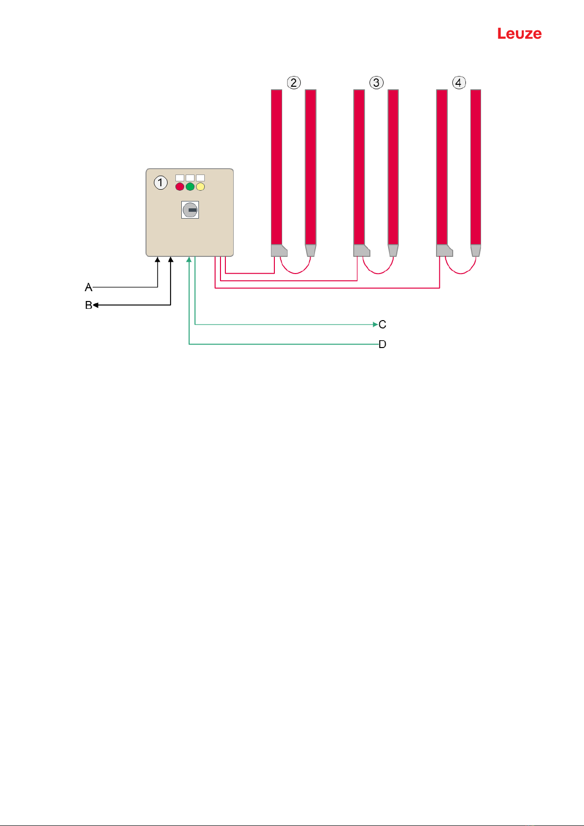
6.1 Connection overview.............................................................................................................32
6.2 Connecting the power supply within the UL scope of application .........................................33
6.3 Connecting the power supply outside of the UL scope of application...................................33
6.4 Connecting light curtains.......................................................................................................35
6.5 Connecting the air wipe unit..................................................................................................37
6.6 Connecting PROFINET.........................................................................................................38
6.7 EMC-compliant installation ...................................................................................................39
6.7.1 Grounding the evaluation unit ...........................................................................................39
6.7.2 Grounding the light curtain housing...................................................................................40
6.7.3 Shielding and line lengths..................................................................................................41

Table of contents
Leuze electronic GmbH + Co. KG CMS 748i 4
7 Starting up the device ........................................................................................42
7.1 Plugging in the software dongle............................................................................................42
7.2 Switching on and off..............................................................................................................42
7.3 Setting up the system coordinate origin................................................................................43
7.4 Setting up light curtains.........................................................................................................44
7.4.1 Setting up the width and height light curtains....................................................................45
7.4.2 Setting up the length light curtain ......................................................................................45
7.5 Determining the height offset ................................................................................................46
7.6 Determining the width offset .................................................................................................48
8 System configuration via webConfig tool ........................................................49
8.1 Start webConfig tool..............................................................................................................49
8.2 Display of the process data...................................................................................................50
8.3 Configuration of the light curtains .........................................................................................51
8.3.1 Setting the system coordinate origin .................................................................................51
8.3.2 Setting the offset for height detection................................................................................52
8.3.3 Setting the offset for distance measurement.....................................................................53
8.3.4 Blanking areas...................................................................................................................54
8.3.5 Adjust and teach in sensitivity ...........................................................................................54
8.4 Configuration of the evaluation .............................................................................................55
8.5 Configuration of the output log..............................................................................................56
8.6 Designation of the contour measurement system in the network .........................................56
9 PROFINET interface description .......................................................................57
9.1 Device control module ..........................................................................................................57
9.2 Result data module ...............................................................................................................58
9.3 Error codes ...........................................................................................................................59
10 Care, maintenance and disposal .......................................................................60
11 Service and support ...........................................................................................61
12 Technical data .....................................................................................................62
12.1 General specifications...........................................................................................................62
12.2 Connections of the evaluation unit........................................................................................65
13 Order guide and accessories.............................................................................69
13.1 Part number code .................................................................................................................69
13.2 Scope of delivery ..................................................................................................................69
13.3 System components .............................................................................................................69
13.4 Accessories...........................................................................................................................70
14 EC Declaration of Conformity............................................................................71

About this document
Leuze electronic GmbH + Co. KG CMS 748i 5
1 About this document
These operating instructions contain information about the intended use of the CMS700i contour measure-
ment system. It is included in the delivery contents.
Used symbols and signal words
Tab.1.1: Warning symbols and signal words
Symbol indicating dangers to persons
Symbol indicating possible property damage
NOTE Signal word for property damage
Indicates dangers that may result in property damage if the measures for dan-
ger avoidance are not followed.
CAUTION Signal word for minor injuries
Indicates dangers that may result in minor injury if the measures for danger
avoidance are not followed.
WARNING Signal word for serious injury
Indicates dangers that may result in severe or fatal injury if the measures for
danger avoidance are not followed.
DANGER Signal word for life-threatening danger
Indicates dangers with which serious or fatal injury is imminent if the measures
for danger avoidance are not followed.
Tab.1.2: Other symbols
Symbol for tips
Text passages with this symbol provide you with further information.
Symbol for action steps
Text passages with this symbol instruct you to perform actions.
Symbol for action results
Text passages with this symbol describe the result of the preceding action.

Safety
Leuze electronic GmbH + Co. KG CMS 748i 6
2 Safety
The CMS700i contour measurement system and its components were developed, manufactured and
tested in accordance with the applicable safety standards. It corresponds to the state of the art.
2.1 Intended use
The contour measurement system is designed as a measuring and object-detecting, configurable, multi-
sensor unit.
Areas of application
The contour measurement system is designed for the measurement and detection of objects for the follow-
ing areas of application in handling and warehousing systems, the packaging industry or a comparable en-
vironment:
• Dimensional measurements such as length, width and height
• Orientation angle of measured material on a transport medium
• Contour measurement
CAUTION
Observe intended use!
The protection of personnel and the device cannot be guaranteed if the device is operated in a
manner not complying with its intended use.
ÄOnly operate the device in accordance with its intended use.
ÄLeuzeelectronicGmbH+Co.KG is not liable for damages caused by improper use.
ÄRead these operating instructions before commissioning the device. Knowledge of the oper-
ating instructions is an element of proper use.
NOTICE
Comply with conditions and regulations!
ÄObserve the locally applicable legal regulations and the rules of the employer's liability insur-
ance association.
NOTICE
Provisions regarding the UL scope of application
When using the switch cabinet of the CMS700i contour measurement system within the UL
scope of application, only the labels on the inside that are marked with a corresponding UL sym-
bol apply.
When using the switch cabinet of the CMS700i contour measurement system outside of the UL
scope of application, only the label on the outside applies.
The power supply cable installed standard is approved for use within the UL scope of applica-
tion. If necessary, it can also be used outside of the UL scope of application.
Outside of the UL scope of application, the switch cabinet should be connected to the power
supply according to the applicable local legal regulations and provisions. This may involve re-
moving the power supply cable installed standard.
NOTICE
The evaluation unit of the contour measurement system may only be opened for the following
purposes:
- for plugging in or unplugging the software dongle, see chapter 7.1 "Plugging in the software
dongle".
- for viewing the inside label within the UL scope of application.
- for connecting to the power supply outside of the UL scope of application.

Safety
Leuze electronic GmbH + Co. KG CMS 748i 7
2.2 Foreseeable misuse
NOTICE
Do not modify or otherwise interfere with the device!
ÄDo not carry out modifications or otherwise interfere with the device. The device must not be
tampered with and must not be changed in any way.
ÄThere are no user-serviceable parts inside the device.
ÄRepairs must only be performed by LeuzeelectronicGmbH+Co.KG.
NOTICE
The evaluation unit of the contour measurement system may only be opened for the following
purposes:
- for plugging in or unplugging the software dongle, see chapter 7.1 "Plugging in the software
dongle".
- for viewing the inside label within the UL scope of application.
- for connecting to the power supply outside of the UL scope of application.
Any use other than that defined under "Intended use" or which goes beyond that use is considered im-
proper use.
In particular, use of the device is not permitted in the following cases:
• in rooms with explosive atmospheres
• in circuits which are relevant to safety
• for medical purposes
2.3 Competent persons
Connecting, mounting, commissioning and adjustment of the contour measurement system must only be
carried out by competent persons.
Requirements relating to competent persons:
• They have a suitable technical education.
• They are familiar with the rules and regulations for occupational safety and safety at work.
• They are familiar with the operating instructions of the contour measurement system and the compo-
nents.
• They have been instructed by the responsible person on the mounting and operation of the contour
measurement system and of the components.
WARNING
Electrical work!
Electrical work must be carried out by a certified electrician.
Certified electricians
Electrical work must be carried out by a certified electrician.
Due to their technical training, knowledge and experience as well as their familiarity with relevant standards
and regulations, certified electricians are able to perform work on electrical systems and independently de-
tect possible dangers.
In Germany, certified electricians must fulfill the requirements of accident-prevention regulations DGUV
(German Social Accident Insurance) provision 3 (e.g. electrician foreman). In other countries, there are re-
spective regulations that must be observed.

Safety
Leuze electronic GmbH + Co. KG CMS 748i 8
2.4 Disclaimer
LeuzeelectronicGmbH+Co.KG is not liable in the following cases:
• The device is not being used properly.
• Reasonably foreseeable misuse is not taken into account.
• Mounting and electrical connection are not properly performed.
• Changes (e.g., constructional) are made to the device.

Device description
Leuze electronic GmbH + Co. KG CMS 748i 9
3 Device description
3.1 Device overview
The CMS748i contour measurement system is an overall system that consists of the following compo-
nents:
• 3 CML730 measuring light curtains (height, width and length measurement)
• 1 evaluation unit (switch cabinet, LSC-Box)
3
4
1
3
2
5
5
4
1 Measurement object
2 Evaluation unit
3 Light curtain – Length measurement
4 Light curtain – Height measurement
5 Light curtain – Width measurement
Fig.3.1: Contour measurement system with 3 light curtains
The evaluation unit performs the capture, processing and preparation of the data.
The system makes the process data available via the PROFINET interface.
Peripheral devices such as scales, bar code readers and cameras can be integrated. The evaluation unit
transfers the data of the peripheral devices in the interface protocol.

Device description
Leuze electronic GmbH + Co. KG CMS 748i 10
1 Evaluation unit (switch cabinet, LSC-Box)
2 Light curtain - Height measurement
3 Light curtain - Width measurement
4 Light curtain ‑ Length measurement
A Voltage supply
B Ethernet TCP/IP (CMS708i)
C Fieldbus OUT (CMS748i, PROFINET)
D Fieldbus IN (CMS748i, PROFINET)
Fig.3.2: Device overview

Device description
Leuze electronic GmbH + Co. KG CMS 748i 11
3.2 Evaluation unit
3.2.1
Connections
1 2 3 4 5 6
1 Voltage supply
2 Grounding bolts
3 M12 Ethernet connection
4 3x interfaces for CML730 light curtains (CML1…CML3)
1x interface for rotary encoder (ENCODER)
5 2x M12 sockets, each with 2 switching inputs (DI1, DI2)
2x M12 sockets, each with 2 switching outputs (DO1, DO2)
6 PROFINET fieldbus interface (FBIn, FBOut)
Fig.3.3: Connections of the evaluation unit

Device description
Leuze electronic GmbH + Co. KG CMS 748i 12
3.2.2
Indicators and operational controls
12
4
5
3
1 LED1 (white)
2 LED2 (green)
3 LED3 (yellow)
4 Door lock
5 Main switch
Fig.3.4: Display and operating elements on the evaluation unit
Tab.3.1: LED indicators
Display Color State Description
LED1 White ON Power supply
LED2 Green ON System ready
LED3 Yellow ON Fault at the peripheral elements (light curtains, rotary encoder)

Functions
Leuze electronic GmbH + Co. KG CMS 748i 13
4 Functions
4.1 Operating principle
The contour measurement system captures the following data of an arbitrarily shaped measurement object:
• Length, width, height of the smallest enclosing cuboid
• Orientation angle to the transport direction
• Smallest vertical distance between object and conveyor belt of the conveyor
Measurements
• All measurement objects are measured continuously.
• Start of measurement: Interruption of the first beam of the length light curtain or triggering of an optional
upstream trigger.
• End of measurement: All beams of the width and height light curtains are free again.
• After the measurement, the evaluation unit automatically forwards the calculated object data to a host
via the communication interface.
Data of other peripheral devices such as scales and bar code readers can also be transferred in the in-
terface protocol.
After the data have been output, the next object can be detected.
NOTICE
Important for reliable measurements!
ÄWhile the measurement is running, do not also interrupt the beams of the light curtains
through manual interventions or other actions. This falsifies the measurement values.
ÄObserve the minimum object distance (see chapter 4.5 "Minimum distance between two
measurement objects") and the maximum conveyor speed (see chapter 4.6 "Maximum con-
veyor speed").

Functions
Leuze electronic GmbH + Co. KG CMS 748i 14
Tab.4.1: Example sequence of a measurement
1. Light curtain for length measurement: First beam interrupted
2. Measurement starts
3. Detection of height and width of the measurement object.
Trigger: Light curtain for length measurement
4. Light curtain for width measurement: All beams free
5. Measurement ends
6. Output of the object dimensions, of the orientation angle and of the
smallest object distance to the edge of the conveyor – acc. to the
configuration
4.2 System resolution
The resolution is determined from the beam spacing of the measuring light curtains. The contour measure-
ment system is delivered in two standard resolutions.
Tab.4.2: Standard resolutions
System resolution/beam spacing Measurement range for height, width, length
5 mm ≤1200mm
10 mm >1200mm
Once the contour measurement system contains at least one light curtain with a measurement field length
>1200mm, the overall system is delivered with a system resolution of 10mm.
NOTICE
Please note that the system resolution influences the following features:
- the minimum distance between two measurement objects (see chapter 4.5 "Minimum distance
between two measurement objects")
- the maximum conveyor speed (see chapter 4.6 "Maximum conveyor speed")
- the infeed spacing of the length light curtain to the beam plane of height and width light cur-
tains (see chapter 5.1 "Installation with three light curtains")

Functions
Leuze electronic GmbH + Co. KG CMS 748i 15
4.3 Object angle of rotation, object length and object width
Object angle of rotation
The object angle of rotation determined by the contour measurement system is the angle between the
lengthwise edge of the measurement object and the vector of the conveying direction.
• The object angle of rotation can take values between -45° and +45°.
• If the magnitude of the object angle of rotation is > 45°, the length and width assignments are ex-
changed and the smaller angle is output with inverted sign.
Object length
The object length or length is – in the top view – defined as the side of the measurement object that has an
angle with a magnitude of less than 45° to the conveying direction (= lengthwise direction).
Object width
The object width is – in the top view – defined as the side of the measurement object that is adjacent to the
object length.
11
1
3
33
2
1 Measurement object
2 Conveying direction
3 Distance between measurement object and edge of conveyor
Fig.4.1: Relationship between magnitude of the object angle of rotation and assignment of object length and ob-
ject width
Tab.4.3: Object angle of rotation and assignment of object length and object width
Output of object angle of rotation -20° +30° (instead of -60°)
Object length A B
Object width B A
4.4 Projections and deformations on the measurement object
This chapter describes the operating principle of the suppression of projections and the detection of defor-
mations on the measurement object.
The settings for these functions are made in the webConfig tool (see chapter 8 "System configuration via
webConfig tool").
4.4.1
Function
The evaluation of measurement objects for projections and deformations occurs in two steps.
Projection detection
In the first step, projections in length, width and height are determined from the raw data of the measure-
ment object according a defined threshold value and then suppressed (see chapter 4.4.2 "Projection sup-
pression"). Projections on the measurement object that do not impede the further handling can, thus, no
longer influence the object measurement.

Functions
Leuze electronic GmbH + Co. KG CMS 748i 16
Deformation detection
In the second step, the contour measurement system uses the raw data of the measurement object that
has been reduced by the amount of the protrusions to determine the cuboid corners of the measurement
object and then determine deformations between the cuboid corners. The determination of the deforma-
tions is referred to as deformation detection (see chapter 4.4.3 "Deformation detection").
Deformation detection can only be selected in combination with projection detection.
Example
A measurement object with projection and deformation is present.
• Projection ∆X has width ∆A.
• The deformation has a maximum value of Xnet-Xmin
∆A Width of the projection
X Overall dimension of the measurement object
∆X Height of the projection
Xmin Dimension of the measurement object without projection and deformation
Xnet Dimension of the measurement object without projection
Fig.4.2: Example object with projection and deformation
The following cases can occur
Deformation de-
tection
Switched off Switched on
Projection threshold
value
∆A>threshold
value
∆A≤threshold
value
∆A>threshold
value
∆A≤threshold
value
Evaluation of pro-
jection
∆X counts towards
the object
∆X is projection and
does not count to-
wards the object
∆X counts towards
the object
∆X is projection and
does not count to-
wards the object
Output of ACTUAL
object dimension
X X X Xnet
Output of SPECI-
FIED object dimen-
sion
X Xnet X Xmin
Deformation output
(Deformations
present)
None None None Arrow indicating di-
rection of deforma-
tion with output
Xnet–Xmin in mm
Error message None None "Deformation detec-
tion not possible"
None
Status OK OK NOK OK

Functions
Leuze electronic GmbH + Co. KG CMS 748i 17
Projections and deformations on the measurement object can occur in the length, width and height direc-
tions.
The illustration of a measurement object on a conveyor shows the orientation of the directional information.
• The red bars represent the light curtains.
• The gray arrows indicate the conveying direction.
1
2
3
3
4
55
5
4
4
3
2
2
1
1
1 Measurement object
2 Conveying direction
3 Length
4 Width
5 Height
Fig.4.3: Depiction of the directional information
NOTICE
The orientation of the directional information and the descriptions of projection suppression and
deformation detection are each depicted using an example of a contour measurement system
with three light curtains.
Projection suppression and deformation detection occur in the same way for contour measure-
ment systems with rotary encoder for the length measurement.

Functions
Leuze electronic GmbH + Co. KG CMS 748i 18
4.4.2
Projection suppression
Projections can occur in the length, width and height directions.
NOTICE
The descriptions of the projection suppression are depicted using the example of a contour
measurement system with three light curtains.
Projection suppression occurs in the same way for contour measurement systems with rotary
encoder for the length measurement.
Projection suppression, length
If the width of the projection ∆A is less than the entered threshold value, the projection is suppressed and
not taken into account in the length measurement.
12
3
4
1 Measurement object
2 Conveying direction
3 Projection
4 Length
∆A Width of the projection
Fig.4.4: Object projection in length (schematic)
Projection suppression, width
If the width of the projection ∆A is less than the entered threshold value, the projection is suppressed and
not taken into account in the width measurement.
12
3
4
1 Measurement object
2 Conveying direction
3 Projection
4 Width
∆A Width of the projection
Fig.4.5: Object projection in width (schematic)

Functions
Leuze electronic GmbH + Co. KG CMS 748i 19
Projection suppression, height
If the width of the projection ∆A is less than the entered threshold value, the projection is suppressed and
not taken into account in the height measurement.
1
3
4
2
1 Measurement object
2 Conveying direction
3 Projection
4 Height
∆A Width of the projection
Fig.4.6: Object projection in height (schematic)

Functions
Leuze electronic GmbH + Co. KG CMS 748i 20
4.4.3
Deformation detection
The contour measurement system sees bulges that protrude from the projected view of the measurement
object as deformations.
Xmin Dimension of the measurement object without deformation
Xnet Dimension of the measurement object with deformation
Fig.4.7: Top view of a measurement object with lateral deformation
Limits of deformation detection
Deformations that protrude into the measurement object and are shadowed by edges cannot be detected
by the contour measurement system. In the case depicted here Xnetwould be <Xmin.
Xmin Dimension of the measurement object without deformation
Xnet Dimension of the measurement object with inward protruding deformation
Fig.4.8: Measurement object with inward protruding deformation
If the smallest enclosing perimeter of the measurement object (red) is much smaller than the object perime-
ter (blue), then a deformation cannot be distinguished from the remaining object structure.
In this case, the contour measurement system outputs the status NOK after the measurement as well as
the length, width and height of the smallest enclosing cuboid – including all projections of the measurement
object.
Fig.4.9: Example object: The smallest enclosing perimeter (red) is less than the object perimeter (blue).
This manual suits for next models
1
Table of contents
Other Leuze Measuring Instrument manuals

Leuze
Leuze AMS 384i User manual

Leuze
Leuze MA 255i Parts list manual

Leuze
Leuze AMS 308i User manual

Leuze
Leuze AMS 304i User manual

Leuze
Leuze AMS 348i User manual

Leuze
Leuze BPS 300i User manual

Leuze
Leuze CML 720i User manual

Leuze
Leuze AMS 335i User manual

Leuze
Leuze AMS 300i Parts list manual

Leuze
Leuze AMS 307i User manual