Delton 4300 User manual

Digital Earth Resistance Tester
4300

Table of contents
1.General Introduction..............................................................................1
2.Safety Rules........................................................................................1/2
3.Performance Features.............................................................................2
4.Technical Indicators............................................................................2/3
5.Operation Diagram..............................................................................3/4
6.Operation Instruction..........................................................................4/7
7.Battery replacement...............................................................................8
8.Maintenance...........................................................................................8
9.Accessories.............................................................................................8

1
1. General Introduction
This Digital Earth Resistance Tester is a new generation tester for
electrician practice which is developed by our company in recent years.
The circuit, structure and technique of traditional earth resistance tester
have been improved and the new design is both fine-looking and
practical. This one has more complete functions, higher accuracy, more
convenient and reliable for operation and more suitable for outdoor use
with dust and wet proof structure. It can test earth resistance of various
earth systems including power systems, electric equipment, lightning
conductors as well as resistance value of low resistance conductor and
AC voltage test.
2. Safety Rules
⑴Please read this manual carefully before use.
⑵It should not be used before placing the back cover back to avoid risk
of electric shock.
⑶Please do not touch lead terminal and circuit under test to avoid
electric shock.
⑷Please make sure the range select switch setting within the proper
range before test.
⑸Make sure the couple plug of lead inserted in the terminal tightly.
⑹When the tester is wet, do not use it or replace battery.
⑺Please do not turn the switch during test.
⑻Please do not test in flammable places since sparkles may cause
explosion.
⑼Please stop use when metal is exposed due to breakage of casing or
testing wire. Make sure the isolation skin of testing wire is intact before
use.
⑽Please make sure the testing wire has been removed from testing
terminal and the range select switch is on off position before replacing
battery
⑾Please make sure the range select switch is on off position after use.

2
⑿Be extremely careful not to get electric shock as a maximum voltage
of 50V is present between terminals (E-C and E-P) during measurement.
⒀Do not apply voltage greater than 200V between terminals E-P .
⒁Do not use this instrument to check an earth of a commercial power
supply or for voltage measurement when making simplified
measurement using an earth of a commercial power supply.
⒂“1 ”shows overrange. Select the higher range and re-test.
⒃Replace battery when “ ” shown on tester or the battery indicator
light is off to ensure testing accuracy. Please remove the battery if not
use it for long time.
3. Performance Features
⑴Measuring range of earth resistance: 0-2000Ω.
⑵Measuring range of earth voltage: 0-200V.
⑶3 1/2 digit LCD display for more direct and convenient reading.
⑷Size of LCD: 68×55mm (Height of character is 35mm).
⑸Response time: Measure earth resistance, about 5 seconds. Measure
earth voltage, about 2 seconds.
⑹Withstand voltage: AC 1500V, 1 minute between circuit and outer
casing.
⑺Overload protection : On earth voltage, can withstand 300V AC (1
minute). On earth resistance, can withstand 200VAC (10 seconds).
⑻Power supply: 1.5V×6 R6PAASUM-3 batteries.
⑼Dimensions: 218×122×75mm.
⑽Weight: about 900g (contain battery).
⑾Working environment:
Working temperature: 0℃~40℃, relative humidity<80%
Storage temperature: -10℃~50℃, relative humidity<85%
Ensure accurate temperature: 23℃±5℃relative, humidity<75%
4. Technical Indicators
Earth resistance

3
Range
accuracy
resolution
20Ω
±(2% rdg + 0.1Ω)
0.01Ω
200Ω
±(2% rdg + 3dgt)
0.1Ω
2000Ω
1Ω
Earth voltage
Range
accuracy
resolution
200V
±(1.0% rdg + 4dgt)
0.1V
5. Operation Diagram
①“C(H)”port (current pole)
②“E”port (earth electrode)
③“P(S)”port (electric potential pole)
④LCD display
⑤Earth resistance test indicator light
⑥TEST key: Earth resistance testing button
⑦CDS sensor: The CDS sensor can reaction to the ambient
brightness range, then automatically control the LCD backlight to
lighten or go out.
⑧HOLD key: Press the “HOLD” key to lock display value, and the
“HOLD” sign will appear on the display, press it again to exit.
⑨Function switch

4
6. Operation Instruction
⑴Battery Voltage Check
If a battery symbol “ ” shows, do not proceed with testing.

5
Risk: maximum 50V voltage may be generated between E-C or E-P
terminals when testing earth resistance!
Please do not touch testing lead to avoid electric shock.
Please make sure testing wire plug insert in testing terminal thoroughly
before testing since loose connection may cause error in testing result.
⑵Test Leads Connection (Precise measurement)
Stick the attached auxiliary earth spikes in line and connect the test leads
as shown below.
Punch assistant earth bar P(S) and C(H) in earth 5 to 10 meters distant
from tested earth substance, Connect green wire to terminal E, yellow
wire to terminal P(S) and red wire to terminal C(H).
Note: Please place assistant earth bar in land with high water content.
You need add water in dry land, sand land or land containing crushed
stones to maintain humidity of inserting position of earth bar.
Lie earth bar flat and add water when meeting cement ground and cover
wet towel, etc on earth bar before testing.
E: Connects earth electrode port
P(S): Connects electric potential pole port
C(H): Connects current pole port

6
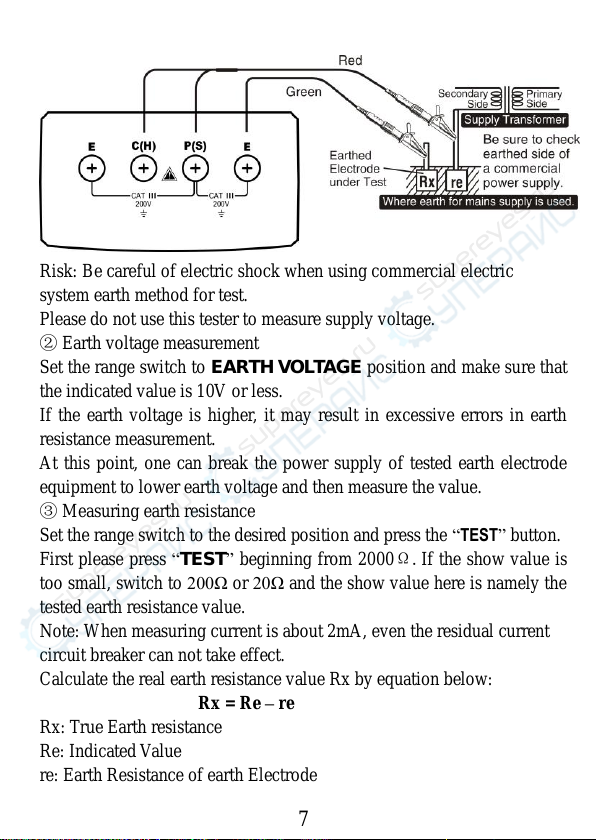
⑶Earth Voltage Measurement
Set the range switch to EARTH VOLTAGE position and make sure that
the indicated value is 10V or less.
If the earth voltage is higher, it may result in excessive errors in earth
resistance measurement.
At this point, one can break the power supply of tested earth electrode
equipment to lower earth voltage and then measure the value.
⑷Checking of Auxiliary Earth Spikes Connection
(Check Function of Auxiliary Earth Resistance)
Set the range switch to 2000Ωposition and press the “TEST”button. If
the auxiliary earth resistance is too high, the “. . .”blinks.
Reduce the resistance by rechecking the connection, changing the site to
stick earth spikes, or pouring water over the spikes.
⑸Measurement (Precise Measurement)
Set the range switch to the desired position, press the “TEST”button.
First please press “TEST”beginning from 2000Ω.If the show value is
too small, switch to 200Ω or 20Ω and the show value here is namely the
tested earth resistance value.
Note: Make sure connecting wires separated during wire connecting
since testing when testing leads wind about with each other may
encounter mutual inductance to affect reading. The assistant earth
resistance value may be too big and error may occur be too big and error
may occur to show value. Make sure assistant earth bar P(S) and C(H)
into wet land and complete contact of connecting parts.
⑹Measurement (Simplified measurement)
When auxiliary earth spikes can not be stuck, an approximate earth
resistance can be obtained by two-wire system designed to make
measurement using an existing earth electrode.
Make sure to use the specified simplified measurement probe.
①Connecting testing wires.
Please connect simple testing wires according as shown below.

7
Risk: Be careful of electric shock when using commercial electric
system earth method for test.
Please do not use this tester to measure supply voltage.
②Earth voltage measurement
Set the range switch to EARTH VOLTAGE position and make sure that
the indicated value is 10V or less.
If the earth voltage is higher, it may result in excessive errors in earth
resistance measurement.
At this point, one can break the power supply of tested earth electrode
equipment to lower earth voltage and then measure the value.
③Measuring earth resistance
Set the range switch to the desired position and press the “TEST”button.
First please press “TEST”beginning from 2000Ω.If the show value is
too small, switch to 200Ω or 20Ω and the show value here is namely the
tested earth resistance value.
Note: When measuring current is about 2mA, even the residual current
circuit breaker can not take effect.
Calculate the real earth resistance value Rx by equation below:
Rx = Re –re
Rx: True Earth resistance
Re: Indicated Value
re: Earth Resistance of earth Electrode

7. Battery replacement
⑴When the battery voltage drop below proper operation range, the
“ ” symbol will appear on the LCD display and the battery need
to changed.
⑵Before changing the battery, set the range switch to “OFF” position.
⑶Open the cover of the battery cabinet by a screwdriver.
⑷Replace the old battery with the same type battery.
⑸Close the battery cabinet cover and fasten the screw.
Caution: Dispose the used batteries according to the rules, which are
defined by each community.
8. Maintenance
This is a precise instrument and needs careful maintenance.
⑴Don’t open the back lid at will. Don’t use it if the back lib not fixed.
⑵Put it in the place dry and airiness if the meter will be leave unused
for long term.
⑶Don’t change the inner circuit at will or the meter maybe out of use.
If there is any problem, contact with us please.
9. Accessories
⑴Assistant earth bar: 2 bars
⑵Testing wire: 1 set
(including red testing wire 15 meters each, yellow testing wire 10
meters each and green testing wire 5 meters each)
⑶Simple testing wire: 1 set
(including red testing wire 1.6 meters each and green testing wire 1.6
meters each)
⑷1.5V (R6PAA) battery: 6 piece
⑸User’s manual: 1 piece
Table of contents