DeLuxe Stitcher DB75V User manual

1
WARNING!
DB75V Loop
Stitching Heads
Machine operators and others in the work area should always wear
safety glasses to prevent serious eye injury from
fasteners and flying debris when loading, operating,
or unloading the stitcher machine.
Do not operate this stitcher head without all stitcher machine
guards in place. Do not modify the guards in any way.
Always disconnect the power supply before removing
any guards for servicing.
Never operate the machine with wire feeding through
the head unless there is stock above the clinchers,
otherwise serious damage may result.
Always turn power off when making adjustments. Always
disconnect the power cord before any disassembly work.
EYEWEAR
REQUIRED

2

Introduction ........................................................................................................4
Specifications .....................................................................................................5
Installation .......................................................................................................6
Pre-Inspection ................................................................................6
Inspection ......................................................................................6
Mounting ...................................................................................... 6-8
Assembly .......................................................................................9
Operation ........................................................................................................9
Wire Threading ........................................................................... 9-10
Wire Straightening ........................................................................11
Adjustments and Settings .......................................................... 12-14
Maintenance ......................................................................................................14
Lubrication ....................................................................................14
How to Order Spare Parts .............................................................16
Troubleshooting ................................................................................................17
Formed Staple Chart .....................................................................18
Appendices ......................................................................................................19
Exploded Drawings ..................................................................... 19-28
Notes .............................................................................................29
Part Number/ Description Cross Reference Index...................... 30-31
Registration Card .............................................................................................32
Wear/Replacement Parts ..............................................................................33
Warranty Information ......................................................................................34
Table of Contents
3

The DeLuxe Stitcher Müller-Martini Replacement Heads, along with a complete
line of fully interchangeable replacement parts are available for current Müller-Martini
users. Anywhere the HK75V is utilized the DeLuxe Stitcher DB75VHDL can be used.
The DB75VHDL has a stitching capacity from 2 sheets up to 3mm (.118”) and will
accommodate 25 gauge round wire. The perfect replacement head for Müller-Martini
Stitchers 221, 235, 321, 335, Prima, Bravo and more, the DB75VHDL is completely
interchangeable.
The DB75VHD & DB75VSHD have a stitching capacity from 2 sheets up to 6mm
(.236) and will accommodate wire sizes from 20-28 gauge round as well as 21 x 25 and
20 x 24 flat. This replacement head for Müller-Martini Stitchers 301, Tempo, Optima,
Supra and the like, is also completely interchangeable.
Each of these heads weighs 7 lbs (3.2 kgs.) independently. The packaged shipping
weight including the wire guide spring, clincher plate assembly and user manuals is
10 lbs. (4.5 kgs.).
Always use a high quality galvanized wire so the plating does not peel. Excessive
peeling will cause clogging and the premature wear of many components. Use only
specified wire gauge for .
2 sheets - 1/8” (3mm) .......................... 25 gauge
NOTE: ALL PRODUCTS ARE MANUFACTURED BY DELUXE STITCHER.
Introduction
4

Weight
Shipping Weight ..............10 lbs (4.5 kg)
Box Dimensions . . . . . . . . . . . . . . 21" x 10" x 7" (53 x 25 x 18 cm)
Stitcher Head
DB75VHDL ........7 lbs (3.2 kg)
Physical Dimensions
Height ...................8.5” (22 cm)
Width ...................3.5” (9 cm)
Depth ...................4.25” (11 cm)
Stitching Capacity
DB75VHDL ........Two Sheets to 1/8” (3 mm)*
Wire Types ...................25 round
Stitcher Machine Compatibility
...................Valore
...................Minuteman
...................Fox, 221, 235
...................Bravo
...................Presto, 300
...................Prima, 331, 335
*Actual stitching thickness capacity depends on the type of stock being stitched and the capacity of the
saddle stitcher being used.
Specifications
5

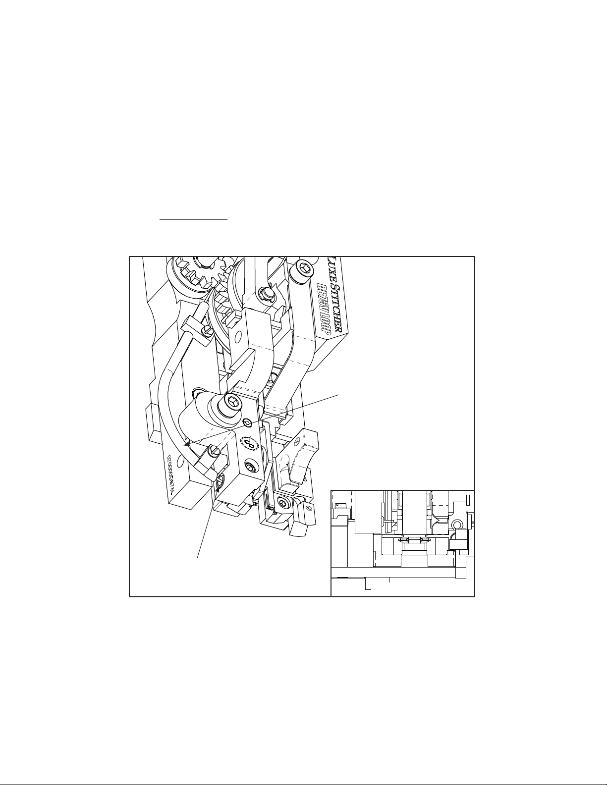
Attaching the Feed Release Handle (Figure 2)
From out of the box, secure the Feed Release Handle
[070119] to the stitcher head by slipping the handle over the
Feed Release Cam Assembly [070118] and securing it with
the provided screw, inserting it through the spring. Make sure
the handle is angled toward the outside of the head when the
screw is tightened.
Carefully inspect the condition of the shipping container before unpacking your replacement Head
for Müller-Martini Stitchers. If the container is broken or damaged and there is evidence that the
stitcher head may be damaged, immediately
notify the carrier who delivered the head and the
DeLuxe Stitcher Graphic Arts Representative
from whom the head was purchased.
Installation
6
Pre-Inspection
As you carefully unpack the replacement
head, check to make sure all components
were delivered and are in good working
order. Use Figure 1 in this manual for refer-
ence to the following pieces:
• Replacement head for Müller Martini
Stitchers: DB75HD, DB75VHD or
DB75VSHD
• Wire guide spring [070286]
• Clincher plate assembly [077030 or
077030C]
• Feed release handle [070119]
• 2.5, 3, 4 and 5 mm hex key wrenches
[G20361, G20360, G20373 and G20362]
• Stitch samples
Inspection (Figure 1)
Figure 1 - Inspection
070286
077030 (DB75) or
077030C (DB75V/VS)
070119
G20360
(3 mm)
G20362
(5 mm)
G20361
(2.5 mm)
G20373
(4 mm)
Mounting & Assembly (Figure 2-6)
Figure 2- Feed Release Handle
Screw
Spring
Handle

7
Wire Guide
Spring
070286
Feed
Release
Handle
070119
Mounting Strap
077027B Mounting
Screw
072013
Lock Washer
G20520
Bender Slide
070162A or
070562A
Driver Slide
070151A or
070551A
Feed Release
Cam
070118
Washer
071006 (2)
Screw
072017 (2)
Figure 4 - Attaching the
Wire Guide Spring
Bonnet Rail
Bonnet Key
Figure 3a - Mounting the Head
Figure 3b - Mounting
Variation for DB75VS
Mounting the Head ( See Figure 3)
Attaching the Wire Guide Spring (Figure 4)

8
Figure 6 - Aligning
Clincher Plate Assembly
Clincher Mounting
Bar
077016
Clincher Plate Assembly
Mounting
Screws
072012 (2)
Clincher Slide
077014 or
077029C
Figure 5 - Mounting Clincher Plate Assembly
Always disconnect the power before assembling
or making adjustments to your stitcher machine.
!
CAUTION
!
Clincher Front
Plate
077018 Clincher Front
Plate
077019
Lock Washers
G20520 (2)
Mounting the Clincher Plate (Figure 5 & 6)
Clincher Points
077015 (2)

Operation
Wire Threading (Figure 7-8)
9
Feed Release
Handle
070119
Wire Holder
Retaining Spring
070183 or 070583
Wire Oiler
Felts
G20293
Small Feed
Gear
070112
Large Feed
Gear
070510A
Retaining Spring
Screw
072004
Figure 7 - Wire Threading
DISENGAGE
GEARS
ENGAGE
GEARS
Wire Guide
Spring
070286
Wire
Wire Nozzle
070181
WIRE TUBE
070544

Before the Stitcher Machine is turned on, release the Wire Holder Assembly [070135A] (Not
shown-See Fig. 7) secured by the Wire Holder Retaining Spring [070183 or 070583] by loosening
the Screw [072004] on the front of the head. Thread the wire from the Spool under the studs on the
Wire Guide Spring (070286), between the Wire Oiler Felts [G20293] on the Spring and into the
Wire Nozzle [070181]. Turn the Feed Release Handle [070119)] clockwise so that the Small Feed
Gear [070112] is disengaged from the Large Feed Gear [070510A].
Continue to push wire through the Replacement Head until the end of the wire passes the Small and
Large Feed Gears, enters the Wire Tube [070544] and begins to come out the bottom of the wire tube.
Then using a small screw driver, wedge the wire up until it enters the Fixed Wire Cutter [070600C].
Engage the Small and Large Feed Gears by turning the Adjustable Lever counter-clockwise.
Note: It will take two full cycles for the proper length staple to come out of the head.
10
Fixed Cutter
070600C
Wire Tube
070544
Bottom View
Figure 8 - Wire Threading

11
Wire Straightening (Figure 9)
Once threaded, cycle the
Stitcher Machine and watch
the wire feeding out of the
the Cutter Box [070197A or
070597A] to the right of the
Moving Cutter [070145C].
The wire should be traveling
in an approximate horizontal
direction when exiting the
Cutter Box.
Top-to-Bottom Adjustment
If the wire is feeding in an
upward or downward direction,
the Wire Straightener
[070206A] will have to be
adjusted. Loosen the Screw
[G20589] securing the Wire
Straightener to the Cutter Box.
If the wire is feeding in an
upward direction, slide the Wire
Straightener down slightly.
Conversely, if the wire is feeding in a downward direction, slide the Assembly up slightly. Make
sure to tighten the Screw after every adjustment to see accurate results. Allow enough Wire to be fed
through the Head so that an accurate assessment can be made. Make sure the ends of each cut piece
of wire is free of burrs, which would negatively affect the driving and clinching of the formed Wire.
Figure 9 - Wire Straightening
Make sure the Wire Holder Assembly has
been removed before tripping the Machine
to avoid jams and the chipping of parts.
WARNING
!
Moving
Cutter
070145C
Wire
Straightener
070206A
Screw
G20589
Bad
Good
Bad
CUTTER BOX
WIRE TRAVEL

Setting the Stitch’s Right Leg (& Setting It's Center)
If after a few stitches, the length of the stitch’s right leg is too short or too long, you will need to
make adjustments. Adjustments are always made to the right leg to compensate for the length of the
left leg. First adjust the stitch’s right leg to match the left and then make adjustments for the overall
length of the stitch or wire
draw.
Power off the Stitcher
Machine and release
the Extension Spring
[074002] from the Feed
Gear Operating Lever Pin
[043002] on the Replacement
Head. Disengage the Small
Feed Gear from the Large
Feed Gear by turning the
Feed Release Handle
[070119]. Push the Feed
Gear Operating Lever
[077001] down which will
move the pin on the Feed
Gear Pinion [070111A] out
of the way of the Feed Gear
Stop [077026]. Loosen, but
do not remove, the Screw
[G20589] securing the Feed
Gear Stop to the top of the
Cutter Box Assembly. If the
legs of the stitch are not even,
do one of the following:
If the right leg is too
short, slide the Feed Gear Stop to the left slightly, to
lengthen it.
If the right leg is too long, then adjust the Feed Gear
Stop slightly to the right.
Adjusting the Length of the Right Leg (Figure 10-12)
Figure 10 - Adjusting the Right Leg
Extension
Spring
074002
Feed Gear
Operating Lever
Pin
043002
Feed Gear
Stop Screw
G20589
Feed Gear
Stop
077026
12
Feed Release
Handle
070119
Right Leg Too LongRight Leg Too Short
Always disconnect the power before assembling
or making adjustments to your stitcher machine.
!
CAUTION
!
Feed Gear
Pinion Pin
Figure 11 - Adjusting the Right Leg
Feed Release Handle
070119
Feed Gear Operating
Lever
077001

13
Adjusting the Overall Length of the Stitch (Adjusting the Stitch Gap)
To change the overall length of the stitch, or
more specifically to change the gap between
the legs of the stitch, the position of the
Cutter Box must be adjusted. Begin by
releasing the Extension Spring from the
Feed Gear Operating Lever Pin. Disengage
the Small Feed Gear and the Large Feed
Gear by turning the Feed Release Handle.
Push the Feed Gear Operating Lever down
which will move the pin on the Feed Gear
Pinion Pin out of the way of the Feed Gear
Stop. Loosen the Screw [072006] securing
the Cutter Box to the Stitcher Head.
If the legs are too short, increase the overall
length of the stitch’s legs by sliding the
Cutter Box to the left and if too long, to the
right. Tighten the Screw, attach the Extension
Spring and power on the Stitcher Machine.
Trip the Stitcher to observe the overall length
of the each stitch after the initial adjustment.
Repeat as necessary.
Adjusting the Stitch Gap or Wire Draw (Figure 13)
Power on the Stitcher Machine and jog the Stitcher to observe the length of the stitch’s right leg after
the initial adjustment. Continue to make adjustments and re-test the Head until the length of the
stitch’s right leg is satisfactory.
When set, any one of the stitches below are regarded as good stitches with the two on the left
needing the next step in adjustment and the two on the right as properly set (with amount of gap a
matter of preference).
Good. Legs are equal, but needs gap
adjustment or more or less wire draw.
Good with no further
need for adjustments
LESS WIRE
DRAW/WIDEN
GAP
MORE WIRE DRAW/
NARROW GAP
Cutter Box
Support Screw
072006
Figure 12 - Adjusting the Stitch
Figure 13 - Adjusting the Stitch Gap

14
Adjusting the Clincher Points (Figure 14)
If the clinch on the staple is not tight enough,
the Clincher Points [077015] have to be raised.
Conversely, if the clinch is too tight, the Clincher
Points have to be lowered. This adjustment is made
on the Stitcher Machine and so cannot be completely
explained in this manual as each individual Machine
is different.
The final position of the Clincher Points should
be flush (or slightly above flush) with the Clincher
Plates. The best way to see the position of the
Clincher Points is to jog the Machine where the
Stitcher Head is mounted. When the Driver is at the
lowest position of its stroke, the Clincher Points are
at their highest position. Jog the Stitcher Machine
until the Stitcher Head is just past this point to reveal
the Clincher Points’ position. To be sure that the
Points are at the best position possible, run a few test
stitches and compare the clinched staples.
Figure 14 - Adjusting Clincher Points
Clincher Points
077015 (2)
Driver
090314-23
Maintenance
Lubrication (Figure 15)
Use any standard S.A.E. #10 oil for lubricating the heads. Heads that are in constant operation
should be lubricated daily. Heads that are operated periodically should be lubricated every five pound
wire spool change or every month, which ever comes first. Usually, only a drop of oil is required at
each lubrication point. Care must be taken that those parts of the head that contact the work to be
stitched are free of oil. Lubricate regularly instead of excessively. Excessive lubrication will result
in work becoming spotted with oil. Use one drop of oil in the following lubrication points:
Always disconnect the power before assembling
or making adjustments to your stitcher machine.
!
CAUTION
!

1. At the top of the
Bonnet [070000 or
070500] on either
side of the Driver
Slide [070551A or
070151A] and Bender
Slide [070162A or
070562A].
2. In the hole of the
Feed Cam Plunger
Bushing [077010].
3. On the shaft of the
Feed Release Cam
Assy. [070118] in the
front of the Small
Feed Gear [070112]
4. The oil hole in the
front of the Bonnet
[090500] - this
lubricates the Clutch
Bearing located
inside the Feed Gears
5. On the Cutter
Operating Lever
[070230] behind the
Cutter Box [070197A or 070597A].
6. In between the Wire Holder Retaining
Spring [070183 or 070583] and the Wire Holder
[070135A] and on the Hook Pivot Pin [073009]
in the Wire Holder [070135A]
7. On each of the Clincher Point Pivot Pins [077018-2] on the Clincher Back Plate [077018]
15
Figure 15 - Lubrication and Cleaning
1
3
4
5
6
2
7

???
16
Feed Gear Information (Figure 16)
Correct clutch assembly.
1
Figure 16 - Feed Gear Pinion Assy
F
r
e
e
w
h
e
e
l
T
r
a
n
s
m
i
t
T
o
r
q
u
e
Always disconnect the power cord before
any maintenance is done or adjustments are
made to the Müller Replacement Head
!
CAUTION
In time, you will need to replace some parts in your DBS75LOOP style Stitcher Head. When this
happens, first locate the needed part in one of the following diagrams. Then locate the DeLuxe
Stitcher part
number and contact your Graphic Arts Representative to order the part by the part number,
Ordering Spare Parts
800-634-0810
DELUXE STITCHER
solving your wire stitching needs for 125 years...

17
The quality and quantity of work that can be produced with the Müller Replacement Head is
dependent upon the operator making all adjustments as accurately as possible and carefully
maintaining the head. The cause of staple imperfections usually can be traced to inaccurate settings
or normal wear of moving parts. In the event of trouble of this nature occurring, the operator can,
by referring to the following troubleshooting chart, quickly locate and remedy the cause or causes
of the trouble.
The following is a brief list of problems and possible solutions which should cover the majority of
situations encountered when stitching with the DB style Stitching Heads.
Troubleshooting (Figure 17)

Figure 17 - Troubleshooting
problem: Right Leg Short
solution: Move the Feed Gear Stop to the right, slightly.
(See page 11)
problem: Right leg Long
solution: Move the Feed Gear Stop to the left, slightly.
(See page 11)
problem: Corner Buckled
solution: Check the Driver for a chipped corner and rotate or replace it
if needed. Use a heavier gauge wire.
problem: Leg(s) Buckled
solution: Check the Wire Cutters and Wire Cutter Operating Slide for
wear and rotate or replace if needed. Use a heavier gauge wire.
problem: Crown Buckled
solution: Check Supporter Spring tension on the Head. If it is too loose
replace it.
problem: Stitch in Pieces
solution: Clean and lubricate the Head. Check for hard or brittle wire and
replace. Check the tension of the Wire Holder Spring and replace Spring if
too loose. Look for wear in Wire Holder pivot point in Bonnet.
problem: Loose Clinch
solution: Raise the Clincher Points. (See page 15)
problem: Legs are Spread or Contracted
solution: Make sure the wire is feeding straight through the Head. (See
page 10) Check the Wire Cutters for wear and rotate or replace if needed.
Check the Formers for wear in the grooves and replace if needed.
problem: Wire jam near Feed Gear
solution: Tighten Cutters. Check for the following worn parts and replace
if necessary. Fixed Cutter, Moving Cutter, Cutter Operating Slide, Cutter
Operating Lever, Bender Slide Insert, Wire Guide, Hook, Hook Pivot Pin and
Feed Gear Friction Strip.
18

19
077027B
070230
077009
074004
077010 070181
G20297
070286
G20292
G20293
G20287
G20298
071006
072017
G20195
073010
090500
072013
070544
070244
072009
071004
070119
073006
070112
070118
073002
Bonnet & Wire Guide Sub-Assemblies

20
Bonnet & Wire Guide Sub-Assemblies
070112 0881.0003.4 Feed Gear, Small 1
070118 0881.0018.4 Feed Release Cam Assembly 1
070119 0022.027 Feed Release Handle 1
070181 0881.0009.4 Upper Wire Tube 1
070230 0881.0006.4 Cutter Operating Lever 1
070244 0881.0043.4 Wire Tube Clamp 2
070286 0881.0301.3 Wire Guide Spring assembly 1
070544 0249.1014.4 Lower Wire Tube 1
071004 0031.5103 Lock Washer, Ribbed 2
072009 0030.3434 Screw M3x0.5x10 2
072013 0030.9001 Screw M6x1.0x22 1
072017 0881.0041.4 Screw M5x0.8x5.5 2
073002 0031.0759 E-Ring 1
073006 0031.6212 Spring Pin, M3x12 1
073010 0881.0030.4 Dowel Pin, M6x32 1
074004 0034.237 Compression Spring 1
077009 0881.0032.4 Feed Cam Plunger 1
077010 0881.0035.4 Feed Cam Plunger Bushing 1
090500 0249.1072.2 Bonnet 1
077027B 0881.0325.4 Mounting Strap, DB75V 1
G20195 0030.1725 Screw M6x1x8 2
G20287 0034.2254 Wire Oiler Felt Spring 1
G20292 0881.0302.4 Wire Oil Felt Washer 2
G20293 0881.0303.4 Wire Oiler Felt 2
G20297 0030.3494 Screw M6x1x40 1
G20298 0030.3494 Hex Nut M6x1 1
DELUXE PART
NUMBER
MÜLLER PART NUMBER
CROSS REFERENCE
PART
DESCRIPTION
QTY.
Table of contents
Other DeLuxe Stitcher Sewing Machine Accessories manuals