DEMA 294CDF User manual
I-148 Pg. 1 of 3
Rev. A0500
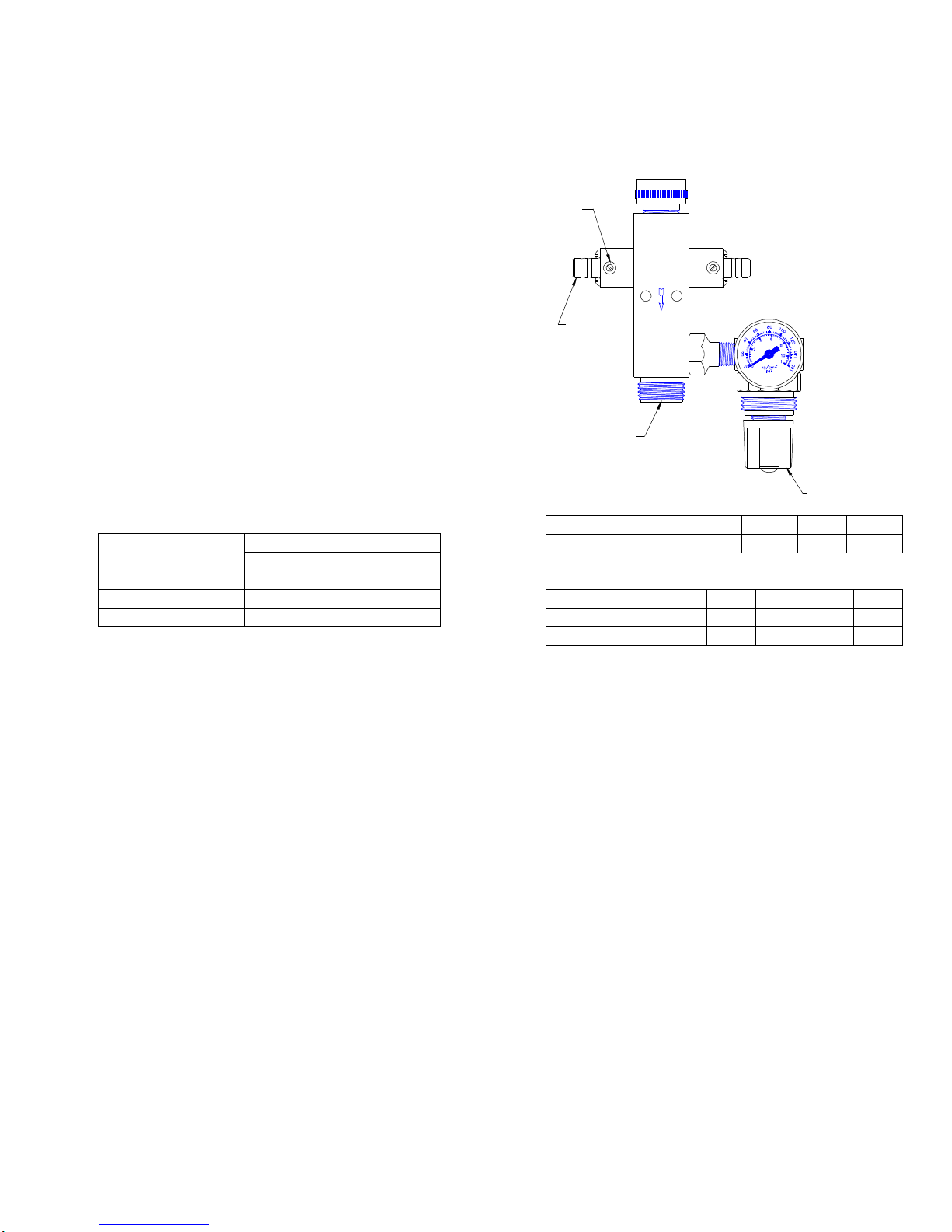
FOAM OUTLET
FIGURE 1
DETERGENT INLET
METERING SCREW
WATER INLET
PRESSURE REGULATOR
AND GUAGE
AIR INLET
DEMA SPRAY FOAM MODEL 294CDF
(DUAL FEED, LINE PRESSURES)
INSTALLATION INSTRUCTIONS
1. PARTS
A. Foamer assembly
B. 2 pcs. plastic supply tubing with strainer
*C. Outlet hose ¾” ID x 25’ lg.
*D. Shutoff valve
*Optional
2. INSTALLATION
A. Water inlet is ¾” garden hose swivel. It may be removed if
attaching to ½” pipe.
B. Air Inlet is ¼” NPT female pipe.
C. Foam outlet is ¾” garden hose. See Table 1 for hose
limitations.
D. Detergent may be drawn directly from any size container
which is usually set on the floor. Use the plastic tubing for
connecting to the injector barbs. First cut to desired length
and then drop the end with the strainer into the container.
MIN. PRESSURES
HOSE SIZE AND
LENGTH WATER AIR
25' of 3/4" ID 40 PSI 40 PSI
50' of 3/4" ID 50 PSI 40 PSI
25' of 1/2" ID 60 PSI 40 PSI
TABLE 1
VISCOSITY CPS 1 75 220 500
MAX. OZ/GAL. 33 31 28 24
TABLE 2
PRESSURE PSI 40 50 60 80
WATER FLOW GPM 1.4 1.6 1.7 2.0
AIR FLOW SCFM 3.5 4.2 4.8 6.1
TABLE 3
3. OPERATION
Open shutoff valve at end of hose. Turn on air supply. Set pressure at 40 PSI. Turn on water supply.
4. ADJUSTMENT
WARNING: Use care when handling hazardous chemicals. Adjust detergent feed rate by turning recessed screws in the square
knobs. Turning to the left increases the rate to the maximums shown in Table 2. To increase dryness of foam, raise air pressure 5
PSI. Repeat if necessary. See Table 3 for water and air flows.
5. SERVICING
CAUTION: Turn off air and water supplies before servicing.
If flow surges and unit falls to make foam:
A. Is the metering screw backed off?
B. Is the outlet hose too small or too long?
C. Is there sufficient water and air pressure? At least 30 PSI is required.
D. Does the detergent contain a foaming agent?
E. Is the foamer outlet attached to a manifold with too few or too small nozzles? They should have a combined water rating of
20 GPM @40 PSI.
If unit stops operating:
A. Is a foot strainer clogged? Lift from drum and clean.
B. Is a detergent check valve clogged? Remove the 4 screws in a square knob. Remove knob to inspect and clean check valve
ball, spring and o-ring.
CAUTION: When servicing unit be sure that replacement parts have been installed according to drawing. Be certain check valve
parts are in
place.

I-148 Pg. 2 of 3
Rev. A0500
DEMA SPRAY FOAM MODEL 294CDF
(DUAL FEED, LINE PRESSURES)
INSTALLATION INSTRUCTIONS
RETURNS: NO MERCHANDISE MAY BE RETURNED FOR CREDIT WITHOUT DEMA’S
WRITTEN PERMISSION. RETURN MERCHANDISE AUTHORIZATION NUMBER
REQUIRED IN ADVANCE OF RETURN.
WARRANTY: DEMA products are warranted against defective material and workmanship under normal use and
service for one year from the date of manufacture. This limited warranty does not apply to any
products which have a normal life shorter than one year or failure and damage caused by
chemicals, corrosion, improper voltage supply, physical abuse, or misapplication. Rubber and
synthetic rubber parts such as “o”- rings, diaphragms, squeeze tubing and gaskets are considered
expendable and are not covered under warranty. This warranty is extended only to the original
buyer of DEMA products. If products are altered or repaired without prior approval of DEMA,
this warranty will be void.
Defective units or parts should be returned to the factory with transportation prepaid. If inspection shows
them to be defective, they will be repaired or replaced without charge, F.O.B. factory. DEMA assumes no
liability for damages. Return merchandise authorization number, to return units for repair or replacement,
must be granted in advance of return.

I-148 Pg. 3 of 3
Rev. A0500
DESCRIPTION
ACCESSORIES
AIR CHECK VALVE SPRING
3/4" ID X 25' LG. OUTLET HOSE
NOZZLE W/ SOLID STREAM (SUPPLIED)
RETAINER SCREW
1/2" OD VINYL TUBING X 8' LG.
4' LG. SPRAY WAND W/ SOLID STREAM
NOZZLE W/ 40° ANGLE
SPRAY FOAM-MODEL 294CDF
ACCESSORY
93-29
DESCRIPTION
AIR CHECK VALVE O-RING
MACHINE SCREW (4 REQD)
CHECK VALVE SPRING
CHECK VALVE BALL (9/32 DIA STNLS. STL.)
CHECK VALVE O-RING
WATER NOZZLE W/ O-RING
METERING KNOB O-RING
INLET HOSE ADAPTER
OUTLET SHUTOFF VALVE
23-32
METERING SCREW W/ O-RING
METERING KNOB W/ METERING SCREW
CHECK VALVE REPAIR KIT
PRESSURE REGULATOR
24-8-8S
24-11L
25-29
90-15
69-1
61-107-1
24-63
93-1
34-1
FOOT STRAINER
PRESSURE GAGE
CERAMIC WEIGHT
PART N0.
23-10
23-11
23-34-3
23-24
23-32
23-7
23-9
21-8
CHECK VALVE CORE
& O-RING
93-14
23-7
NOZZLE
93-17-4
93-25
93-24
PART N0.
23-24
BALL 1/4 DIA
PRESSURE GAGE
SPRING
ADAPTER
BALL 5/16" DIA
93-28
93-30-1V
100-12L
93-30-2
93-31
93-29
93-6
93-14
93-2
93-17-4
34-1
24-8-8S
93-30-1V
23-9
23-10
23-11
25-29
23-34-3
93-6
21-8
61-107-1
93-30-2
93-31
93-1 93-2
93-24
93-25
90-15
100-12L
93-28
24-11L
Other DEMA Paint Sprayer manuals


Popular Paint Sprayer manuals by other brands

SATA
SATA SATAjet 100 B F RP operating instructions

Mi Swaco
Mi Swaco MONGOOSE PRO Installation and operation manual

Paul B. Zimmerman
Paul B. Zimmerman DS-15 owner's manual

AIRLESSCO
AIRLESSCO Prolight Contractor Series manual

Dow
Dow FROTH-PAK MINI operating instructions

Porter-Cable
Porter-Cable PSH1 instruction manual

Cima
Cima Link Additional Installation, Operation and Maintenance Instructions

DÖRR
DÖRR EcoGun 2100 Operation manual

Jula
Jula Meec Tools Multi Series operating instructions

H.E.R.O.
H.E.R.O. 1150GSD Safety, operating and maintenance instructions

PVA
PVA PVA2000 System manual

Magnum
Magnum TexFinish 246185 Repair


