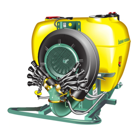
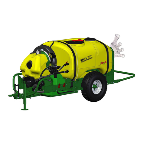
Cima Link Manual

R
LINK
atomizzatori e impolveratori
OPERATION AND
MAINTENANCE INSTRUCTIONS

Dear Customer, thank you very much!
We want to congratulate with you, for having
®
chosen a sprayer.
Your choice shows the wisdom of the well-informed
Purchaser, aware of the fact, that the re uired
features of uality, techni ue and reliability must
be satisfied at the right price!
Our continuous engagement in R&D and in testing
our machines allows us to realize products able to
offer the best performances, a high reliability and
a great easiness of use at the same time !
Our first goal, is to get our Customers happy for
having met us!
The “Spare parts catalogue” of this sprayer/sprayhead isavailable
in the “restricted area” on website www.cima.it.
In order to accede, use
User name sprayer
Password 844719KE

LOW-VOLUME SPRAYERS
TRAILER-MOUNTED MODELS
27040 Montù Beccaria - Loc. Molino Quaroni - (PV) - ITALIA
Tel. +39.0385.246636 r.a. - Fax +39.0385.246637
http://www.cimaitalia.com
S.p.A.
OPERATION AND
MAINTENANCE INSTRUCTIONS
LINK
Model: ...................................................
Serial Number: ...................................................


III
LINK 3-2002
LISTING OF VALID PAGES
This publication consists of 64 pages, subdivided as follows:
N° OF PAGE REVISION BASE
from I to VI 02 March 2002
from 1 to 58 02 March 2002
ADDITIONAL RECORDS AND VARIANTS
REVISION DESCRIPTION
00 First Edition, March 2001
01 Second Edition, January 2002
02 Third edition, March 2002
03
04
05
06
07
08

IV
LINK 3-2002
GENERAL INDEX
1 FOREWORD .......................................................................................................................... 1
1.1 PUBLICATION IDENTIFICATION......................................................................................... 1
1.2 ATTACHED PUBLICATIONS ................................................................................................ 1
1.3 PURPOSE OF PUBLICATION .............................................................................................. 1
1.4 REFERENCE TO REGULATIONS ....................................................................................... 1
1.5 USING THE MANUAL ............................................................................................................1
1.6 UPDATES ...............................................................................................................................2
2 GLOSSARY ........................................................................................................................... 3
2.1 TERMINOLOGY .................................................................................................................... 3
2.2 ABBREVIATIONS ................................................................................................................... 3
2.3 DECALS .................................................................................................................................. 3
3 GENERAL INFORMATION .................................................................................................. 8
3.1 MACHINE IDENTIFICATION ................................................................................................ 8
3.2 TECHNICAL ASSISTANCE ................................................................................................... 8
3.3 SAFETY NOTICES ................................................................................................................ 8
3.4 SAFETY SYSTEMS ................................................................................................................ 9
3.5 HANDLING OF AGRO-CHEMICALS ................................................................................. 10
3.5.1 Storage ................................................................................................................................. 10
3.5.2 Specific equipment ............................................................................................................... 10
3.5.3 Disposal of empty containers and agro-chemical residues ............................................... 11
3.5.4 Personal means of protection ..............................................................................................11
4 MACHINE’S STRUCTURAL ANALYSIS ........................................................................... 12
4.1 FRAME ................................................................................................................................. 13
4.2 FAN SERVO AMPLIFIER..................................................................................................... 17
4.3 HYDRAULIC CIRCUIT COMPONENTS ............................................................................. 18
4.4 TECHNICAL DATA ..............................................................................................................26
4.4.1 Sprayers dimensions and weights ....................................................................................... 26
4.4.2 Wheel’s: dimensions and operating pressures ................................................................... 26
4.4.3 Technical specifications for fans and pump ........................................................................ 27
5 COUPLING MODALITIES .................................................................................................. 28
5.1 HITCHING TO THE TRACTOR .......................................................................................... 28
5.2 MOUNTING OF THE TRANSMISSION SHAFT ................................................................ 29
5.3 INSTALLATION OF REMOTE CONTROLS ...................................................................... 29
V
LINK 3-2002
5.3.1 Manual 2-tap distributor - P8 ................................................................................................ 29
5.3.2 Electrical control panel - E8 ................................................................................................. 30
6 DISTRIBUTION DEVICES .................................................................................................. 31
6. TYPE AND IDENTIFICATION CODES ............................................................................... 31
7 ACCESSORIES .................................................................................................................... 32
7.1 FILLER PIPE ......................................................................................................................... 32
7.2 MANUAL TURN DEVICE ..................................................................................................... 32
8 FILLING ...............................................................................................................................33
8.1 FOREWORD – USE OF THE FAN DISENGAGEMENT ................................................... 33
8.1.a Disengagement of the fan .................................................................................................... 33
8.1.b Fan engagement to perform the treatment .......................................................................... 34
8.2 FILLING THROUGH POURING FROM THE TOP ........................................................... 34
8.3 FILLING WITH THE SPECIFIC PIPE .................................................................................. 35
9 AGITATION ......................................................................................................................... 38
10 TANK AND HYDRAULIC CIRCUIT DRAINING ............................................................... 38
11 OPERATING PROCEDURES ............................................................................................. 39
11.1 PRELIMINARY OPERATIONS TO TREATMENT .............................................................. 39
11.2 PREPARATORY OPERATIONS TO TREATMENT ........................................................... 39
11.3 THE TREATMENT ............................................................................................................... 41
11.4 END OF TREATMENT - STORAGE .................................................................................. 41
11.4.1 Daily ...................................................................................................................................... 41
11.4.2 End of seasonal cycle .......................................................................................................... 42
12 TRANSPORT ....................................................................................................................... 43
13 MAINTENANCE OPERATIONS ......................................................................................... 44
13.1 LUBRICATION ..................................................................................................................... 44
13.2 FAN SHAFT SUPPORT OIL LEVEL CHECK ..................................................................... 45
13.3 FAN SHAFT SUPPORT OIL REPLACEMENT ................................................................... 45
13.4 CLEANING OF FILTER’S CARTRIDGE ............................................................................. 46
13.5 PURGING OF RESIDUES FROM FILTER ........................................................................ 47
13.6 CLEANING OF THE FAN .................................................................................................... 47
13.7 FAN BELT TENSIONER ...................................................................................................... 48
13.8 PUMP BELT TENSIONER ................................................................................................... 48

VI
LINK 3-2002
13.9 TANK REMOVAL OR REPLACEMENT .............................................................................. 49
13.10 TABLE OF MAINTENANCE OPERATIONS ....................................................................... 50
14 FAULTS FINDING ............................................................................................................... 51
15 REPAIRS ALLOWED .......................................................................................................... 53
15.1 REPLACEMENT OF PUMP CONTROL BELT ................................................................... 53
15.2 REPLACEMENT OF ELECTRICAL PANEL’S FUSES ....................................................... 54
15.3 PRESSURE GAUGE REPLACEMENT ............................................................................... 54
16 INTEGRATIVE DIAGRAMS ................................................................................................ 55
16.1 HYDRO-PNEUMATIC DIAGRAM ....................................................................................... 55
16.2 WIRING DIAGRAM .............................................................................................................. 56
17 NOISE LEVEL ...................................................................................................................... 57
18 WARRANTY ......................................................................................................................... 57
19 ATTACHMENT : DECLARATION OF COMPLIANCE .................................................... 58

1
LINK 3-2002
1 FOREWORD 1
1.1 - PUBLICATION IDENTIFICATION
The “OPERATION AND MAINTENANCE INSTRUCTIONS” manual is an integrative part of the sprayers.
It is identified by a Publication No. located on the third cover page, and through which the document
can be identified, traced and/or subsequently referred to.
The information elements contained herein are updated as at the date of publication. C.I.M.A. S.p.A.
reserves the right to modify its machines without notice, with the purpose of applying technical
enhancements, and it declines all responsibility for possible omissions from the publication.
1.2 - ATTACHED PUBLICATIONS
— Spare parts catalogue;
— Distribution devices, “Operation and maintenance instruction”
— Distribution devices, “Spare parts catalogue”
— “Low Volume - Instructions for sprayer adjustment”
— “Modalities for filling through the specific pipe” diagram
— “Modalities for filling through pouring from the top” diagram
1.3 - PURPOSE OF PUBLICATION
All indications contained in this manual are aimed at the user of the sprayer.
The duration of the machine and its operation, the operator’s safety and the respect for the environment
are dependent upon scrupulous observance of the stated norms.
Before making use of the sprayer, the user must read, understand and abide by all regulations listed
in this manual.
1.4 - REFERENCE TO REGULATIONS
This manual was set out conforming to the regulations contained in following documents:
— Attachment “I” to Directive 89/392/C and subsequent modifications (letters “b”, “c” of point 1.1.2
and point 1.7.4);
— UNI EN 907 - 1997 and to all the documents in it quoted.
1.5 - USING THE MANUAL
Read every part of this manual, paying attention to the WARNING and DANGER indications both on
the text and on the machine or on components.
All operations suggested by the manual will have to be followed with the utmost care and only after
having understood the negative consequences of improper usage.

2
LINK 3-2002
The following “symbols “ are used within the text in order to highlight and visually identify the
importance of the various types of information:
Indicates important additional information
Non observance can result in permanent damage to the sprayer.
Highlights possibly dangerous situations to people.
The manual, with relevant attachments and possible integrating issues, must be kept with the utmost
care and must always be complete, integer and legible in every part. Should it be mislaid it is imperative
to immediately request a duplicate from C.I.M.A. S.p.A. Should the decals originally applied on the
machine be mislaid, damaged or become incomprehensible, they should be
promptly replaced.
For every type of distribution device (Head) delivered with the sprayer, a specific user and
maintenance manual is attached. All the head manuals must always accompany the one of the machine.
- The manual must always be kept for the sprayer’s whole operational life.
- Any modification received must be permanently inserted in this publication.
- The manual must be ceded with the sprayer should this be sold.
1.6 - UPDATES
Possible updates that C.I.M.A. S.p.A. will provide the owner of the sprayer will be accompanied by
instructions to insert in this publication.
Should the machine be sold, the owner must inform the new purchaser that he should notify C.I.M.A
S.p.A. of his address in order to receive possible future integrating issues and/or updates.

3
LINK 3-2002
2 GLOSSARY 2
2.1 - TERMINOLOGY
The terms FRONT, REAR, RIGHT and LEFT utilised in this publication refer to the sprayer as seen by
an operator from behind the operative unit along the drive line and facing it: the rear part of the machine
is that closest to the operator, and is where the distribution device (Head) is mounted - and the front
part is the one that gets attached to the tractor.
2.2 - ABBREVIATIONS
g.................................................................................................................................................. grams
h.................................................................................................................................................... hour
ha............................................................................................................................................. hectare
ha/h .......................................................................................................................... hectare per hour
l..................................................................................................................................................... litres
l/h ................................................................................................................................... litres per hour
l/ha ............................................................................................................................ litres per hectare
kg ............................................................................................................................................ kilogram
kg/cm2..................................................................... kilograms per square centimetre (atmosphere)
km.......................................................................................................................................... kilometre
km/h .................................................................................................................... kilometres per hour
Lm............................................................................................................................... width in metres
m................................................................................................................................................. metre
Mesh .................................................................................................... N° of meshes per linear inch
Micron ................................................................................................................. 1/1000 of millimetre
PTO .............................................................................................................................. power take-off
RPM ............................................................................................................................ revs per minute
s.............................................................................................................................................. seconds
2.3 - DECALS
The safety and use/maintenance decals are applied to the machine are described in the following
paragraph.
Every decal is marked with its part number, in case it needs to be replaced.
Safety
1 - 95001 - STOP THE ENGINE AND REMOVE THE KEY FROM THE TRACTOR’S CONTROL PANEL
BEFORE CARRYING OUT ALL MAINTENANCE OR REPAIR OPERATIONS
- Positioned over the servo amplifier unit protection plastic casing.

4
LINK 3-2002
2 - 95004 - DANGER OF CONTAMINATION BY CONTACT OR POISONOUS PRODUCTS INHALA-
TION
- Positioned above the main tank, in the forward part, next to the filler spoutes.
3 - 95005 - DANGER, PARTS IN MOTION. BEFORE REMOVING PROTECTION GUARDS, STOP
THE TRACTOR, REMOVE THE KEY FROM THE TRACTOR’S CONTROL PANEL AND
ENSURE THAT ALL MOVING PARTS HAVE STOPPED
- Positioned on the fan casing next to the outflow vent.
4 - 95008 - THE SPRAYER ISN’T EQUIPPED WITH THE PERSONAL CLEANING ADDITIONAL
TANK
- Visible on the hands-washing tank housing, when this isn’t mounted.
5 - 95015 - BEFORE UTILISING THE RELEASE DEVICE, STOP THE TRACTOR, REMOVE THE KEY
FROM THE TRACTOR’S CONTROL PANEL AND ENSURE THAT THE FAN HAS
STOPPED
- Positioned on the servo amplifier unit protection plastic casing cover.
6 -95010 - MAXIMUM OPERATING SPEED OF THE DRIVE OUTLET (PTO): 540 RPM
- Positioned near the drive outlet.
7 - 95007 - DANGER OF SPRAYS: KEEP AT A SAFE DISTANCE
- Positioned on the upper part of the fan casing.
8 - 95006 - WARNING: CONSULT THE USER AND MAINTENANCE MANUAL BEFORE USING OR
INTERVENING ON THE MACHINE
-Positioned on the left-hand side of the tank, in the forward part of this one.
9 - 95009 - DANGER: GLOVES MUST BE USED TO EMPTY THE TANK
- Positioned on the unit’s left side, near the draining cock.
10 - 95077 - IT IS FORBIDDEN TO ENTER INTO THE TANK!
- Positioned on the tank left side, near the main filler.
Use and maintenance
11 - 95055 - CAUTION, THE UNIT ISN’T HOMOLOGATED FOR CIRCULATING ON ROAD
- Positioned on the tank, in the left front section.
12 - 95079 - CHECK THE OIL LEVEL EVERY 8 HOURS: FAN SHAFT BEARINGS
- Positioned on forward of the chassis, on the left-hand side
13 - 95054 - IGREASE EVERY 200 HOURS: FAN TIGHTENER SUPPORT, FREEWHEEL AND WHEEL
HUBS
- Positioned on the right front side frame
- Positioned in the front section, near the Power Takeoff.
- Positioned on the wheel
- On the drawbar, near the articulated joint.
14 - 95076 - LUBRICATE EVERY 6 MONTHS: PUMP BEARINGS
- Positioned on the left side of the servo amplifier unit protection plastic casing, near the
pump.
- Positioned on the right side of the servo amplifier unit protection plastic casing, near the
additional agitation pump (for the models where it is foreseen)
15 - 95057 - HAND WASHING TANK TAP
- Positioned on the left-hand side of the tank, next to the tap.
16 - 95065 - WARNING: NEVER OPERATE THE SPRAYER WITHOUT LIQUID IN THE TANK
- Positioned on the tank, in the left section.

5
LINK 3-2002
17 - 95069 - INDICATIONS FOR THE USE AND MAINTENANCE OF THE SOLENOID VALVES
- Positioned on the right side of the servo amplifier unit protection plastic casing.
18 - 95060 - INDICATION OF THE WHEELS OPERATING PRESSURE
95056 - Positioned on the frame left and right rear sections.
19 - 95080 - INDICATION ON THE OPERATION OF THE 3-WAY TAP (P3)
- Positioned on the frame on the left side, near the cock (P3).
Positioning of the safety, use and maintenance decals
NOTE: The numbers with the asterisk (*)
indicate the adhesives relevant ei-
ther to optional components or to
accessories to be applied ONLY on
the models and versions on which
this is foreseen.
1
ink S 50
ink S 50
basso volume
100
200
300
400
500
600
700
800
LT
5*
14
12
3
19
913 18
11
16
8
2
10
00320

6
LINK 3-2002
NOTE: The numbers with the asterisk (*) indicate the adhesi-
ves relevant either to optional components or to acces-
sories to be applied ONLY on the models and versions
on which this is foreseen.
L
ink S 50
L
ink S 50
basso volume
basso volume
®
+
-
ONON
OFF OFF
SpinRemoteControl
HO
2
Press.
Pump
18
13 13
13
13
14*
15*
t
4
17*
14
00321
6
15 7
3
10 2 8 16
11
4
18
9
13
t
00322
19

7
LINK 3-2002
* Safety decals
* Use and maintenance decals
1 95001
00042
2 95004 3 95005
00043
00044
5 95015 6 95010
7 95007 8 95006 9 95009
00045
00046
00047
00048
00049
13 95054
14 95067 15 95057 16 95065
00065
00068
00069
00067
00066
4 95008
00199
11 95055
ATTENZIONE
MACCHINA NON OMOLOGATA PER
LA CIRCOLAZIONE SU STRADA
17 95069
18 95056
10 95077
COLLEGAMENTO / SCOLLEGAMENTO TUBO RIEMP.
CONNECTION / DISCONNECTION FILLING PIPE
CONNEXION / DECONNEXION TUYAU DE REMPL
.
CONEXION / DESCONEXION TUBO DE CARGA
C
A
POSIZIONE LAVORO
WORK POSITION
POSITION DU TRAVAIL
POSICION DE TRABAJO
SVUOTAMENTO SERBAT./POMPA
TANK & PUMP DRAINING
DRENAJE DE TANQUE Y BOMBA
VIDAGE CUVE ET POMPE
B
19 95080
00319
00284
18 95060
00283
12 95079
OIL MAX
MIN
8h
CONTROLLARE
CHECK
CONTRÔLER
CONTROLAR
95079
00282

8
LINK 3-2002
3 GENERAL INFORMATION 3
3.1 - MACHINE IDENTIFICATION
3.2 - TECHNICAL ASSISTANCE
C.I.M.A. S.p.A. is at the complete disposal of customers for any type of intervention. The names and
addresses of its service network, both in Italy and in foreign countries, can be requested from:
C.I.M.A. S.p.A. - 27040 Montù Beccaria - Loc. Molino Quaroni (PV) - ITALIA
tel. 0385-246636 - fax 0385-246637
from abroad tel. +39-0385-246636 - fax +39-0385-246637
3.3 - SAFETY NOTICES
All the preparation, use, maintenance, moving and transporting operations must be carried out only
after having acquired a perfect knowledge of the regulations contained in this publication and the ability
to appropriately interpret the symbols of the decals applied to the machine.
IT IS FORBIDDEN TO UTILISE THE SPRAYER FOR PURPOSES OTHER THAN FOR ITS
INTENDED USE, SINCE IT WAS MANUFACTURED ONLY FOR SPRAYING AGRICULTURAL
CROPS WITH ANTI-PARASITIC PRODUCTS.
It is necessary to scrupulously abide by the following general norms:
— always stop the tractor’s engine before carrying out any operation on the sprayer;
— check that the weight and power of the tractor are compatible with the sprayer to be used;
— before utilisation, check the correct tightening and securing of the machine’s various components,
paying particular attention to the safety protections and to the moving parts;
— only utilise protected cardan shafts provided with CE conformity certification.
Carry out the assembly only if the drive outlets of both tractor and sprayer are equipped with the
protection counter-guard;
— check that the cardan shaft is blocked by the appropriate anti-rotation chains;
— keep people and animals away from the machine before starting it up;
00070 Identification nameplate
00323
ink S 50
ink S 50
basso volume
basso volume
100
100
200
200
300
300
400
400
500
600
600
700
700
800
800
LT

9
LINK 3-2002
— don’t wear articles of clothing that might get caught in moving parts;
— keep to a low speed while negotiating bumps or crossing ditches.
- All maintenance and repair operations must be carried out only after having
rinsed the tank and flushed the system.
- Before operating within the tank it is necessary to wash it thoroughly with clean
water.
- It is forbidden to perform welding operations if ammonium salts were previously
used.
- It is forbidden to use the machine within a potentially explosive environment.
-The application of paints and/or solvents, the washing of closed environments
and machinery as well as the utilisation of the air flow for purposes other than
those expressly concerning the spraying of agro-chemicals is not permitted.
- It is forbidden to enter the tank.
3.4 - SAFETY SYSTEMS
All machine moving parts are suitably protected by guards and highlighted through the use of warning
decals.
- It is forbidden to use the machine with these guards removed.
- Before removing the protection, stop the tractor’s engine and remove the key
from the control panel.
The pictures illustrate the machine’s guarded parts:
REMOVABLE PROTECTION COVER
FOR THE FAN
SWITCHING-OFF DEVICE
(For versions in which this is envisaged)
PTO PROTECTION
CASING
00198
L
ink S 50
L
ink S 50
basso volume
®
+
-
ONON
OFFOFF
SpinRemoteControl
HO
2
Press.
Pump
FAN
PROTECTION
GRILL
PROTECTION COVER
FOR
FAN SERVO AMPLIFIER
00321
00322

10
LINK 3-2002
THE OWNER AND/OR THE OPERATOR OF THE SPRAYER ARE NOT PERMITTED TO MODIFY
THE STRUCTURE OR THE SPECIFIC OPERATION OF THE SPRAYER ITSELF. ANY REPAIR-
ING INTERVENTION HAS TO BE CARRIED OUT EITHER AT THE DISTRIBUTORS’ OR AT THE
C.I.M.A. S.p.A. AUTHORIZED WORKSHOPS, OTHERWISE ANY KIND OF WARRANTY
IMMEDIATELY CEASES AND C.I.M.A. S.p.A. IS CLEARED OF ANY CONSEQUENT AND/OR
IMPLIED RESPONSIBILITY.
3.5 - HANDLING OF AGRO-CHEMICALS
The operator could become contaminated due to accidental spray, contact or inhalation of products
or crop-spraying mixtures.
The environment could become polluted by mixture over-spills, puncturing of containers, uncon-
trolled storage of used and unwashed containers or spillage into waterworks.
In order to avoid these risks the preparation and filling operations must be carried out in suitably
appointed and adequately equipped sites.
3.5.1 - Storage
Fixed / stationary: the site used must be well ventilated and secured by lockable doors in order to
prevent even accidental access by children or unauthorised persons.
Mobile: the carrier equipment must be properly locked and kept under conditions whereby access
by children or unauthorised persons can be prevented during the absence of the operator. All full or
partially utilised containers must be secured against tipping, falling or breakage during transportation.
Both types of storage must:
— have a suitable container for the storing of empty packaging materials should a specific storage
area not be available;
— have a clean water supply readily available for washing, by means of a specific container or
through connection to the waterworks system;
— have the use of fire extinguishers, should flammable products and substances be stored.
- All packages, whether whole or partially utilised, must be stored in their original
packing and with the warning instructions clearly displayed and legible.
- The storage indications must always be scrupulously adhered to, as well as their
utilisation and possible disposal as suggested on the product’s original packag-
ing.
3.5.2 - Specific equipment
The site at which the preparation and filling out will take place must provide for:
— all the equipment necessary to the precise measuring of both the water quantity and the dose of
product to be mixed in the tank at every filling;
— all the equipment and means useful to the preparation of the mixture and for the cleaning of the
operator in case of contamination;
— all tools necessary to facilitate the direct introduction of the agro-chemicals in the tank;
— the allocation of clothing and specific equipment in order to avoid contamination by contact or
inhalation during the whole operative phase of the intervention;
— the availability of proper equipment able to stop the uncontrolled spilling and flowing of the mixture;
— a retaining valve on the feed pipe when the filling of the tank takes place directly from the
waterworks system.

11
LINK 3-2002
3.5.3 - Disposal of empty containers and agro-chemicals residues
Agro-chemicals are classified as “special” waste and their disposal must take place separately from
“urban” wastes.
Empty packaging and contaminated containers to be done away with cannot be
dispersed, burned or buried.
The washing water for the cisterns and the tools utilised for the preparation of
mixtures cannot be emptied on the ground, spilled into the sewage system or in
waterways and rivers.
The disposal of special wastes is regulated by specific norms. In order to perform this operation it is
necessary to obtain the relevant information from the Local Offices specifically appointed to rule on
this subject. The non compliance with these regulations can cause considerable damage to persons
and animals as well as polluting the environment.
3.5.4 - Personal means of protection
The toxicity of agro-chemicals forces persons working with them to wear adequate protective clothing
and accessories in order to avoid risks of contamination by contact or inhalation.
In each of the following work stages:
— filling of tanks and adding of the agro-chemical,
— dusting and spraying,
— adjusting of the sprayer,
— emptying and cleaning of the tank,
— replacement of the agro-chemical,
— maintenance interventions,
it is necessary to wear personal protection
clothing and accessories.
The following must be worn:
— Polyethylene or polyvinyl gloves.
— Full, waterproof cotton overalls, in order to
guarantee transpiration, fitted with polypro-
pylene side flaps.
In commerce, one-time ‘tyvek’ overalls are
available which, after use (see picture),
must be disposed of according to the moda-
lities applicable to toxic waste.
— A protective half-mask in polychloroprene rubber with 1 or 2 filters. Filters for gases and organic
fumes, of European A1-class vapours, are envisaged and these can be combined with anti-dust
models of P1 European class, for harmful mists and powders, or P2, for harmful and toxic mists
and powders.
The filters must be replaced:
- when the smell/taste of agro-chemicals can be detected, and that of active A1-
class carbons;
- when difficulty in breathing is experienced for the anti-dust filters of class P1 and P2.
In any case it is necessary to make use of all personal means of protection as
suggested by the manufacturers.
00073

12
LINK 3-2002
4 MACHINE’S STRUCTURAL ANALYSIS 4
The pictures indicate the position of the main components of the sprayer.
00324
00322
PRESSURE
REGULATOR
MAIN
TANK
MAIN FILLER (BP)
UNIT-WASHING
TANK
GAUGE
REAR
FRAME
TANK LEVEL
INDICATOR
BEARING
FEET
PTO
SECONDARY
FILLER (BS)
PUMP
FORWARD
FRAME
JOINING
ELBOW
CENTRIFUGAL
FAN
HAND WASHING
TANK
AXLE
PNEUMATIC
AGITATOR
PLUNGER TAP
ELECTRICAL
DISTRIBUTOR (*)
00256
DELIVERY
FILTER
MANUAL
DISTRIBUTOR
00204
t
(*) For versions in
which this is
envisaged
AGITATION
ADDITIONAL
PUMP (*)
Other manuals for Link
2
Table of contents
Other Cima Paint Sprayer manuals

Cima
Cima BLITZ Avant 50T Manual

Cima
Cima BLITZ Manual

Cima
Cima PLUS Troubleshooting guide

Cima
Cima Plus 42 Troubleshooting guide

Cima
Cima BLITZ 45T Specification sheet

Cima
Cima PLUS Operating and maintenance instructions

Cima
Cima BLITZ Manual

Cima
Cima PLUS Troubleshooting guide

Cima
Cima P42 Troubleshooting guide
Popular Paint Sprayer manuals by other brands

Bareknuckle
Bareknuckle Welterweight APS Operating Instruction and Safety Manual

HARDER & STEENBECK
HARDER & STEENBECK Colanm Instructions for use

WAGNER
WAGNER 2371053 Translation of the original operating instructions

Kobalt
Kobalt KC-599CS quick guide

Seal ‘n Lock
Seal ‘n Lock Pail Pump System Operation manual

DS Produkte
DS Produkte NY038 instructions