Paul B. Zimmerman DS-15 User manual
by PBZ
15 & 25 Gallon Disinfect Sprayer
Model DS-15 & DS-25
Form: DS25OM
Rev: B.1 Date: 05/19
PBZ LLC | 295 Wood Corner Rd | Lititz PA 17543
www.CropCareEquipment.com | (717)-738-7365
A Paul B Zimmerman Inc. Company
Owner's Manual


3
Table Of Contents
Before You Begin....................................................................................3
Identication Of Machine...................................................................3
Safety Precautions.................................................................................4
General Guideline...................................................................... 4
Before Operation.........................................................................4
During Operation........................................................................5
Following Operation..................................................................5
Pump Safety Precautions..........................................................5
Breakdowns & Parts List......................................................................6
DS-15 & DS-25 Breakdown.......................................................6
DS-15 & DS-25 Parts List............................................................7
DS101 Breakdown & Parts List................................................8
DS102 Breakdown & Parts List................................................9
DS103 Breakdown & Parts List..............................................10
DS104 Breakdown & Parts List..............................................11
DS106 Breakdown & Parts List..............................................12
GK50DS Breakdown & Parts List...........................................13
Disinfect System Plumbing Schematic..............................14
Installing the Sprayer........................................................................15
Base Unit Installation (DS-15 & DS-25)...............................15
Filter Unit Assembly..................................................................16
Thank you for purchasing this CropCare product. This owners manual contains helpful information regarding the installation,
operation and maintenance of your product. For parts and service please contact your local CropCare dealer.
Trailer/Drive Axle Nozzle Assembly & Mounting............16
Steering Axle Nozzle Assembly & Installation.................17
Diaphragm Check Valve Assembly & Installation...........18
Bulk Head/Quick Disconnect Assembly & Install...........18
Spray gun Assembly & Installation..... ...............................18
Maintenance & Winterizing Instructions.....................................19
Routine Maintenance...............................................................19
Winterizing Your Sprayer........................................................19
CropCare Limited Warranty .............................................................20
Notes................................................................................................. 21-22
Contact Us..............................................................................................23
• Please read and understand this manual and its instructions and warnings completely before operating the sprayer.
• Be aware of all safety guidelines, warnings, and cautions.
• Completely assemble the sprayer according to the directions supplied in this manual.
• Read and understand the chemical manufacturer’s labels, warnings, and instructions.
• Familiarize yourself and other operators with the sprayer’s components and how all parts are operated.
Before You Begin
Please read and understand this manual and its instructions and warnings completely before operating.
Identication of Machine
• Model #’s: DS-15 & DS-25
• The model number and revision identication decal is located on top of the pump cover.

4
• Carefully study and understand this owner’s manual.
• Read and follow the inoculant or chemical manufacturer’s labels, warnings, and instructions! A material safety data sheet
(MSDS) should be provided by the chemical manufacturer.
• To avoid injury from chemical hazards, wear the proper protective clothing. Each chemical manufacturer’s clothing
requirements are listed under the “Personal Protective Equipment” (PPE) section in the chemical instructions.
• Do not wear loose-tting clothing which may catch in moving parts.
• It is also recommended that operators wear suitable hearing and eye protection.
• Inspect the sprayer for worn parts, loose bolts, or other visible problems, and make the necessary repairs. See the
maintenance section.
• Make sure the area is clear of any people or obstructions before using the sprayer.
• Have all operators practice operating the sprayer and its attachments until all persons are completely capable of safe
operation.
General Guidelines
• The operator should be a responsible adult. Do not allow persons
to operate this liquid applicator until they have displayed a
thorough understanding of applicator safety precautions and
operational use!
• The best defense against accidents is a careful and responsible
operator.
• A chemical warning decal and an owner’s manual warning decal
are located on the applicator’s tank. Be aware of their location. See
Figure 1 and Figure 2.
• Always replace any warning decals that aren’t legible or are missing.
• When transporting the sprayer on public roads, always follow
state and local regulations regarding safety and transportation
requirements.
• If there is any portion of this manual that you do not fully
understand, please contact PBZ LLC.
Safety Precautions
Before Operation
Figure 1: Chemical Warning Decal(# DEMT3980)
Figure 2: Owner's Manual Decal(# DE39)
Every year many unnecessary accidents occur due to improper equipment handling and a disregard for safety precautions. You, the
operator, can avoid accidents by observing the precautions in this section.

5
During Operation
• Always be aware of bystanders, particularly children!
• Keep hands and body parts clear of all moving parts!
• Never leave running equipment unattended.
• Never leave running equipment, including the liquid applicator, unattended!
• Remember that accidents can even happen to seasoned operators. Always take your time and follow all safety instructions.
Pump Safety Precautions
Safety Precautions
• Never pump ammable, explosive, petroleum-based, or any other non-compatible products such as gasoline, fuel oil,
kerosene, etc. Such practices will void the manufacturer’s warranty.
• DO NOT allow the pump to get wet or to be exposed to the elements. Allowing the pump to get wet or to be exposed to the
elements voids the manufacturer’s warranty.
• Note: The pump may be run dry for limited periods without resulting in damage.
• Always disconnect the power to the pump when working on the pump. Failure to do this could result in electrical shock.
Following Operation
• After operation, store the sprayer away from human and livestock activity.
• Do not permit children to play on or around the sprayer.

6
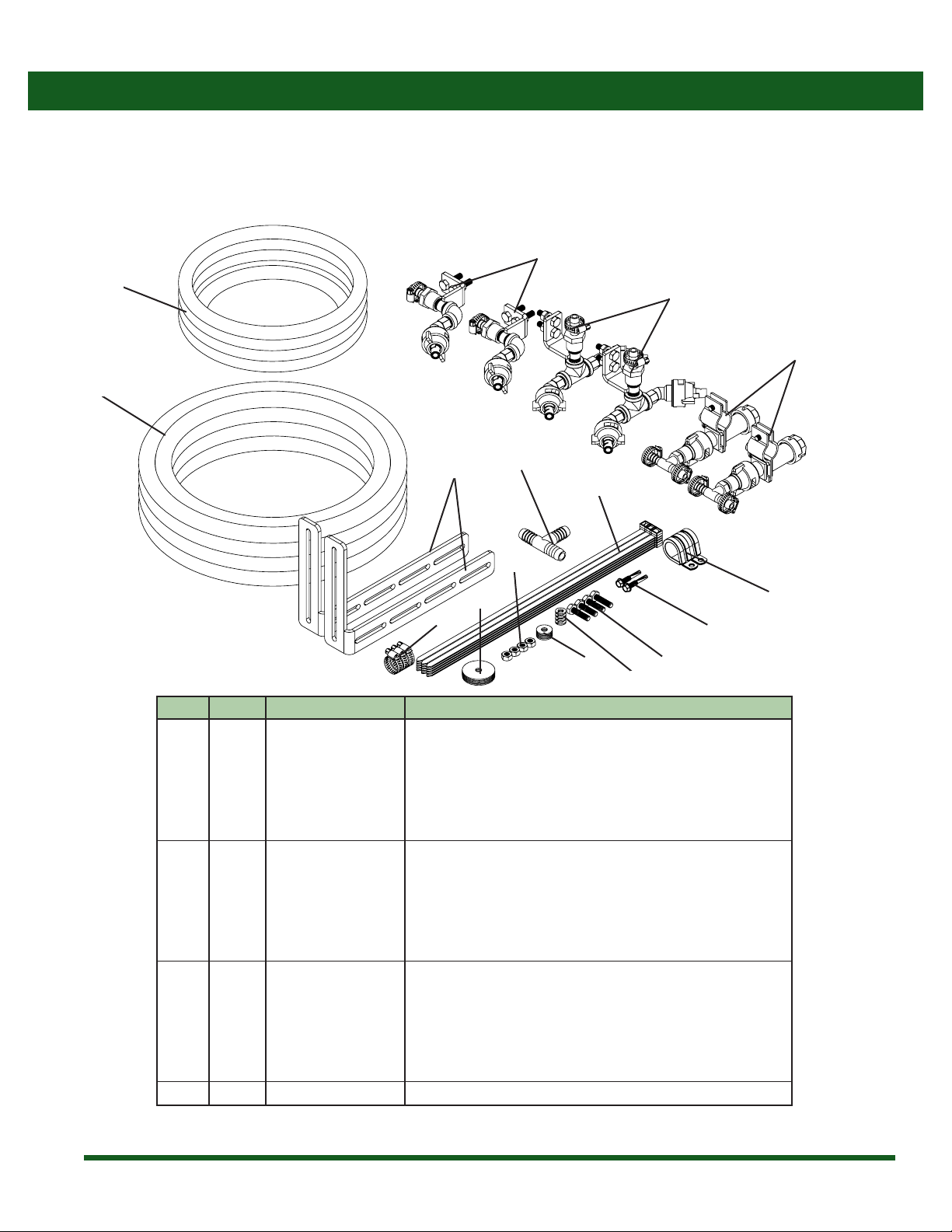
Breakdowns & Parts Lists
Disinfect Sprayer Breakdown
DS-15 & DS-25, Disinfect System Base Assembly
1
2
3
4
5
6
5
7
8
9
10
11
11
12
13
13
18
19
14
16
15
17
2
20

7
Breakdowns & Parts Lists
Disinfect Sprayer Parts List
DS-15 & DS-25, Disinfect System Base
Ref # Qty. Part Numbers Description
1 1.67’ 1208 Hose, EPDM Rubber 1/2”200 PSI
2 2 62606 Hose Clamp, Narrow 5/16”-7/8” SS
3 1 10416D Strainer, Suction 3/8”FPT 40 Mesh
4 1 3A3812 Fitting, Hose 3/8” MPT x 1/2” HB
5 2 3EL1212 Hose adapter, 90°, 1/2” MPT x 1/2” barb
6 1 5537-1G1-63B Pump, Diaphragm 12V 5.3 GPM Demand 75 PSI Viton Santo, Heavy Duty Motor
7 2 DE46 Decal, CropCare logo, 1.9”x 8.8”
8 1 DS106 Filter/Valve Assembly, Disinfect System
9 2 HSS10*12 Screw, Hex TEK #10 x 1/2” SS
10 1 SB25WP-DR + Tank, 25 Gal White Poly w/Lid Lanyard Outlet Cap Gasket&Tether
11 4 SBT316*1 Bolt, Stove Truss Head 10-24 x 1”
12 1 T744 Pump cover, stainless steel
13 2 T743 ATX pump cover, tab
14 1 11042 Gasket, EPDM for 5”Lid
15 1 10035* Lid, Tank 5" w/ out Lanyard
16 1 10873* Lanyard, 12"
17 1 10960* Gasket, Tank Outlet Cap for Den Hartog Applicator Tank
18 1 19024* Cap, Tank Outlet for Den Hartog Applicator Tank
19 1 19025* Tether, Cap Tank Outlet for Den Hartog Applicator Tank
20 1 DE184 Decal, DS-25 Model and Revision
* Components are available as part of the tank (Item 10).
+Shown for DS-25 (25 gallon), use part # SB00015SW with DS-15 (15 gallon).

8
Breakdowns & Parts Lists
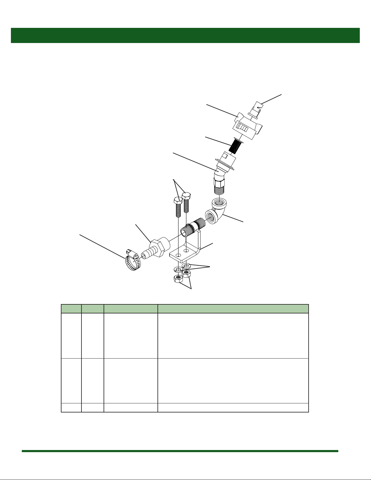
Disinfect Sprayer Breakdown & Parts List
DS101, Nozzle Assembly
Ref # Qty. Part Numbers Description
1 1 62606 Hose Clamp, Narrow 5/16"-7/8" SS
2 2 22674-14-NYB Adapter, Nozzle 45° 1/4”NPT
3 2 256003NYR Cap & Gasket, Quick TeeJet Red
4 1 3AF1438 Adapter, Hose 1/4” FPT x 3/8” HB
5 2 8079PP50 Strainer, Tip 50 Mesh Red Poly Body SS Screen
6 2 H5C14*1 Bolt, Hex 1/4-20 x 1”Gr 5
7 2 LW14 Washer, Lock 1/4”
8 2 NC14 Nut, Hex 1/4-20
9 1 T14S Tee, 1/4”NPT SS
10 1 T533 Gauge mount nipple, 1/4” MPT x 1 1/2”, stainless
11 2 TFVP2 Tip, Turbo FloodJet Polymer Red
1
2
2
3
3
4
5
5
6
7
8
9
10
11
11
9
Breakdowns & Parts Lists
Disinfect Sprayer Breakdown & Parts List
DS102, Nozzle Assembly
Ref # Qty. Part Numbers Description
1 1 62606 Hose Clamp, Narrow 5/16”-7/8” SS
2 1 22674-14-NYB Adapter, Nozzle 45° 1/4" NPT
3 1 256003NYR Cap & Gasket, Quick TeeJet Red
4 1 3AF1438 Adapter, Hose 1/4” FPT x 3/8” HB
5 1 8079PP50 Strainer, Tip 50 Mesh Red Poly Body SS Screen
6 2 H5C14*1 Bolt, Hex 1/4-20 x 1”Gr 5
7 1 L14S Elbow, 90° 1/4”NPT SS
8 2 LW14 Washer, Lock 1/4"
9 2 NC14 Nut, Hex 1/4-20
10 1 T533 Gauge mount nipple, 1/4” MPT x 1 1/2”, stainless
11 1 TFVP2 Tip, Turbo FloodJet Polymer Red
1
2
3
4
5
6
7
8
9
10
11
10
Breakdowns & Parts Lists
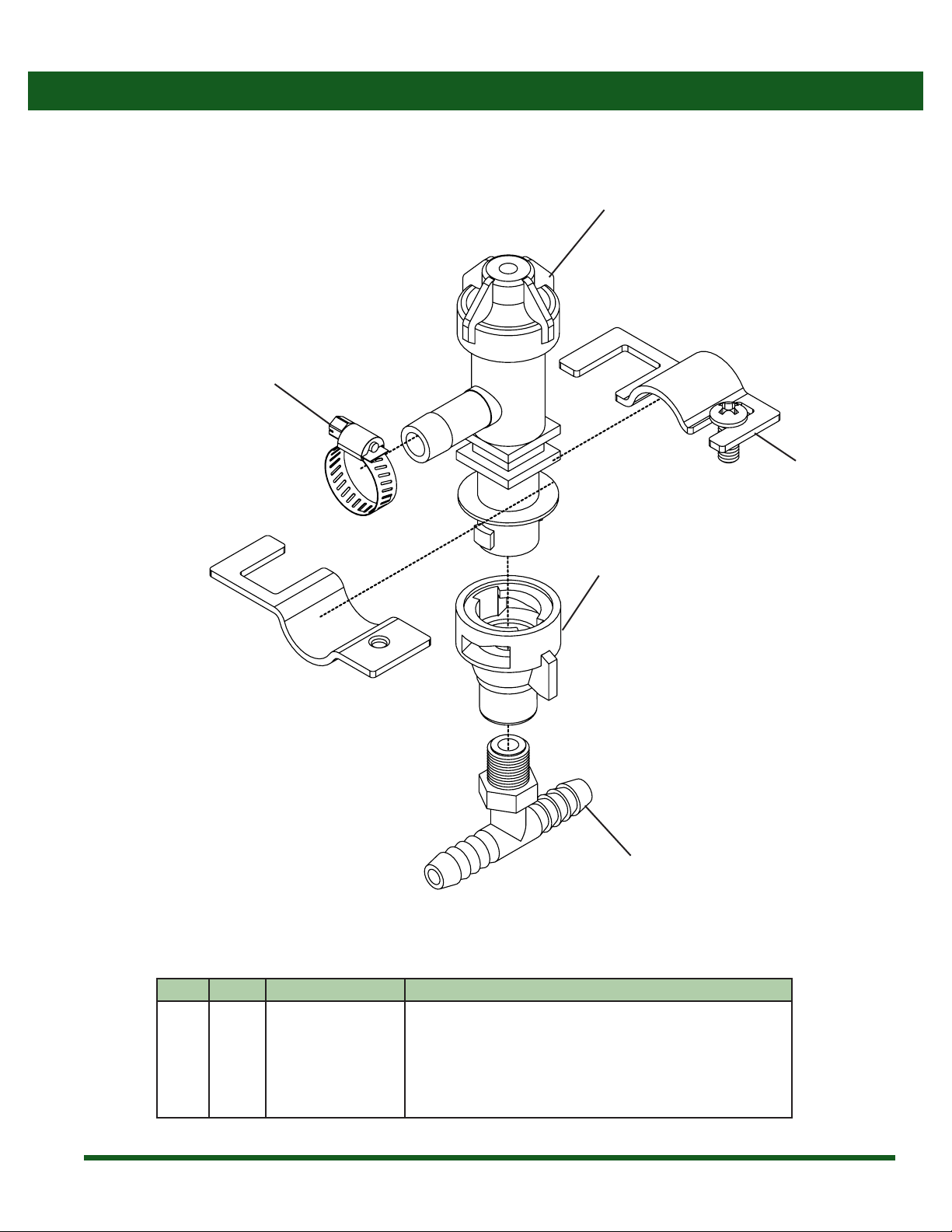
Disinfect Sprayer Breakdown & Parts List
DS103, Disinfect System Check Valve
Ref # Qty. Part Numbers Description
1 1 22251311500NYB Body, Nozzle Elbow 1/2”QJ300
2 1 3T1438T Tee, Fitting 1/4" MPT x 3/8" HB Run Poly
3 3 62606 Hose Clamp, Narrow 5/16”-7/8” SSd
4 1 QJ11112 Clamp, Nozzle Body 1/2" Pipe
5 1 QJ467614NYR Adapter, Cap QJ To 1/4” FPT
1
2
4
5
3

11
Breakdowns & Parts Lists
Disinfect Sprayer Breakdown & Parts List
DS104, Disinfect System Quick Disconnect
Ref # Qty. Part Numbers Description
1 2 62606 Hose Clamp, Narrow 5/16”-7/8” SS
2 1 207-08-08 Fitting, Bulkhead Brass 1/2” NPT
3 1 3A1212 Adapter, Hose 1/2” MPT x 1/2” HB
4 1 3EL1212 Hose adapter, 90°, 1/2” MPT x 1/2” barb
5 1 BST4M Quick Disconnect, Brass, 1/2" MNPT
6 1 BSTN4 Plug, Quick Coupler 1/2” NPT Brass
7 1 SE12S Elbow, Street 90° Stainless 1/2”NPT
1 2
1
3
4
5
6
7
12
Breakdowns & Parts Lists
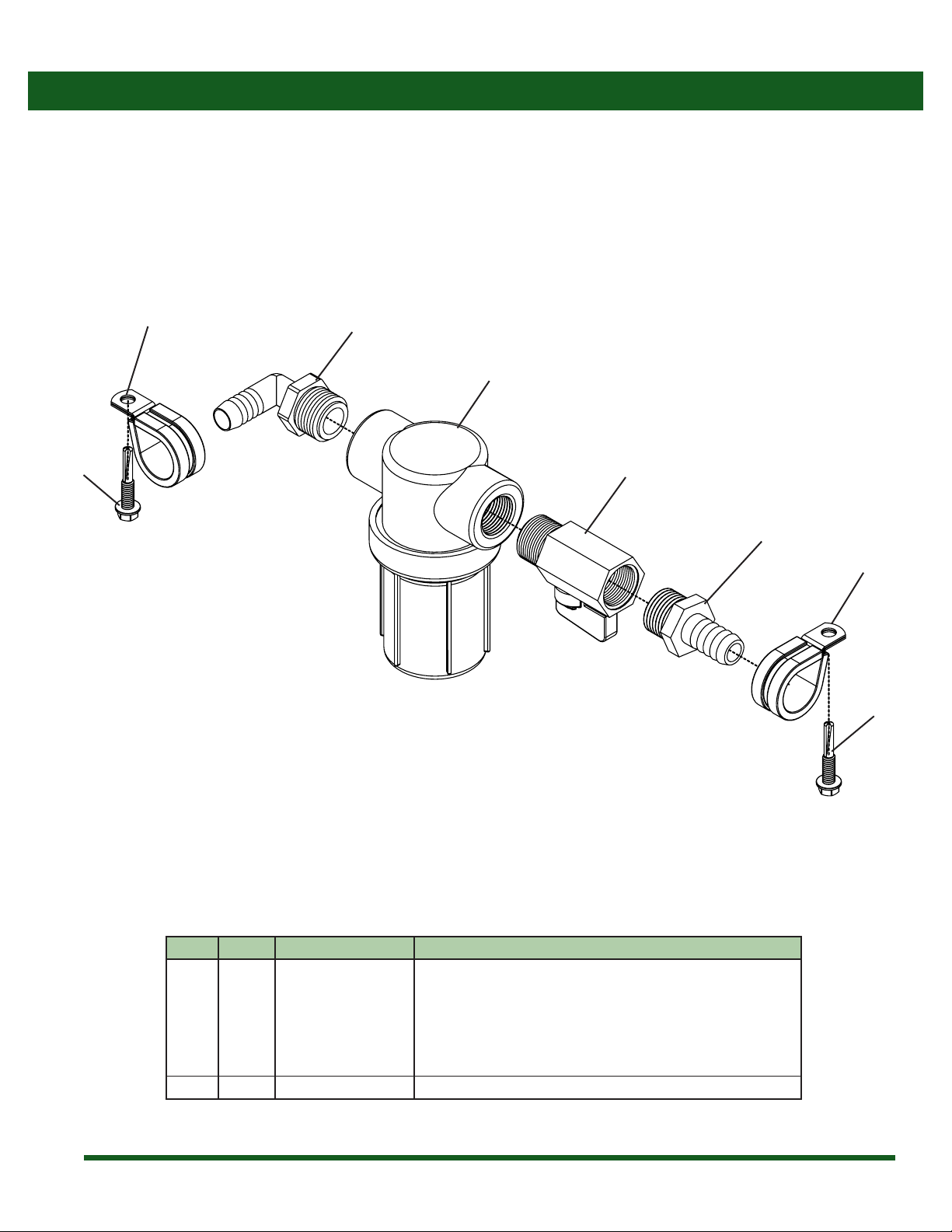
Disinfect Sprayer Breakdown & Parts List
DS106, Disinfect System Filter/Valve Assembly
Ref # Qty. Part Numbers Description
1 1 3A1212 Adapter, Hose 1/2” MPT x 1/2” HB
2 1 3EL1212 Hose adapter, 90°, 1/2" MPT x 1/2" barb
3 1 90FMB12 Valve, Ball 1/2" FPT x 1/2" MPT 300PSI
4 1 AA12212PP50 Strainer, Line 1/2” FPT 50 mesh screen
5 2 DC2014 Clamp, Loom Steel 7/8”
6 2 TK12*114H5 Screw, Tek Hex Head 12-24 x 1-1/4”
1
2
3
4
5
5
6
6

13
Breakdowns & Parts Lists
Disinfect Sprayer Breakdown & Parts List
GK50DS, Disinfect System Filter/Valve Assembly
Ref # Qty. Part Numbers Description
1 50’ 1206 Hose, EPDM Rubber 3/8”200 PSI
2 4 62606 Hose Clamp, Narrow 5/16”-7/8” SS
3 1 9910110131 Adapter, 3/8” HB x 1/2” BSP Wing Nut Assy
4 1 3AF1238 Adapter, Hose 1/2 FPT x 3/8 HB
5 1 3T12T Tee, Fitting 1/2" MPT x 1/2" HB Run Poly
6 1 5062410F Spray Gun, 700 PSI
7 2 DC2014 Clamp, Loom Steel 7/8”
8 2 TK12*114H5 Screw, Tek Hex Head 12-24 x 1-1/4”
12
2
2
3
4
5
6
7
8
14
Breakdowns & Parts Lists
Disinfect Sprayer Breakdown & Parts List
DS-TK, Disinfect System, Tractor/Straight Truck Plumbing Kit
Ref # Qty. Part Numbers Description
1 25 FT 1206 Hose, EPDM Rubber 3/8" 200 PSI
2 55 FT 1208 Hose, EPDM Rubber 1/2" 200 PSI
3 15 1475UV Cable Tie, 14" 75 Lb UV Black
4 3 62606 Hose Clamp, Narrow 5/16"-7/8" SS
5 2 DC2014 Clamp, Loom 7/8" Steel
6 2 DS101 * Disinfect System Nozzle Assembly (Drives and Trailer)
7 2 DS102 * Disinfect System Nozzle Assembly (Steering)
8 2 DS103 * Disinfect System Check Valve
9 4 FDW14*112 Washer, Fender 1/4" ID x 1-1/2" OD
10 4 FW14 Washer, Flat 1/4"
11 4 H5C14*1 Bolt, Hex 1/4-20 x 1" Gr 5
12 4 LW14 Washer, Lock 1/4"
13 4 NC14 Nut, Hex 1/4-20
14 1 T12 Tee, 1/2" Hose Barbs Nylon
15 2 T533BKT Extension Bracket for T533
16 2 TK12*114H5 Screw, Tek Hex Head 12-24 x 1-1/4"
* These items are shown assembled, but will come in individual bags. See individual breakdowns for assembly.
3
4
59
10 11
12
13
14
15
16
2
6
7
8
1

15
Breakdowns & Parts Lists
Disinfect Sprayer Breakdown & Parts List
DS-TR, Disinfect System Trailer Plumbing Kit
Ref # Qty. Part Numbers Description
1 25 FT 1206 Hose, EPDM Rubber 3/8" 200 PSI
2 65 FT 1208 Hose, EPDM Rubber 1/2" 200 PSI
3 50 1475UV Cable Tie, 14" 75 Lb UV Black
4 3 62606 Hose Clamp, Narrow 5/16"-7/8" SS
5 10 DC2014 Clamp, Loom 7/8" Steel
6 2 DS101 * Disinfect System Nozzle Assembly (Drives and Trailer)
7 1 DS103 * Disinfect System Check Valve
8 1 DS104 * Disinfect System Quick Disconnect
9 4 FDW14*112 Washer, Fender 1/4" ID x 1-1/2" OD
10 4 FW14 Washer, Flat 1/4"
11 4 H5C14*1 Bolt, Hex 1/4-20 x 1" Gr 5
12 4 LW14 Washer, Lock 1/4"
13 4 NC14 Nut, Hex 1/4-20
14 1 T12 Tee, 1/2" Hose Barbs Nylon
15 2 T533BKT Extension Bracket for T533
16 10 TK12*114H5 Screw, Tek Hex Head 12-24 x 1-1/4"
* These items are shown assembled, but will come in individual bags. See individual breakdowns for assembly.
4
5
9
10
11
12
13
14
15
16
2
6
7
8
1
3

16
Disinfect Sprayer Schematic
Disinfect Sprayer Plumbing Schematic
DS103 DS103DS103
DS101
DS101
DS101
DS101
DS104
TRAILER DRIVES STEERING
DS102
DS102
“T”“T”
1/2” 1/2”
3/8”
3/8”
3/8”
3/8”
3/8”
3/8”
FILTER VALVE
DS106
DS-25
TANK
PUMP
“T”
GK50DS
3/8”
1/2”
1/2”
NOTE: This is a typical tractor trailer conguration for a DS25.
17
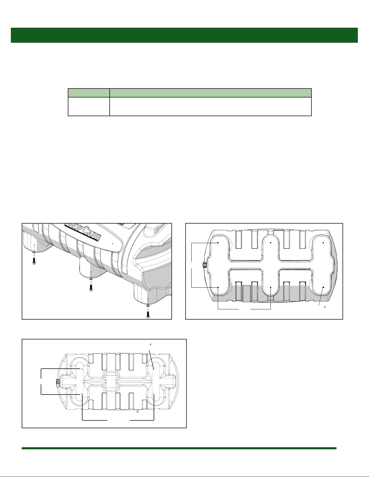
Installing the Sprayer
1. Select a mounting surface for the base unit. Mount the tank on the truck in a location that can withstand the weight of the base
unit with a full tank (approximately 250 lbs).
2. The location of the tank should not cause interference with the operation of the equipment it is mounted on.
3. For optimal stability, mount the liquid applicator with bolts using the six threaded holes in the bottom of the tank.
14”
11 1/8”
5/16
Figure 3: Applicator Unit Mounting Figure 4: Bottom Hole Dimensions (DS-25)
Base Unit Installation (DS-15 & DS-25)
Qty. Description
1 Assembled Base Unit
1 Parts bag with lter assembly components
Base Unit Box Contains:
• NOTE: Measure the distance between the bottom mounting holes because tank measurements can vary up to 1/4”.
• Attach the tank to the desired mounting surface using 5/16-18 bolts.
• IMPORTANT: Make sure that the bolts do not extend more than 1/2”into the tank. Use the shortest bolts possible and spacing
washers as needed to ensure that excess bolt length does not puncture the tank. Do not over-tighten bolts.
6 15/16”
19 3/4”
14”
11 1/8”
5/16
Figure 5: Bottom Hole Dimensions (DS-15)

18
Installing the Sprayer
Filter Unit Assembly and Installation (DS106)
1. Assemble components from lter unit package as shown on
page 12. Use Teon tape and/or thread sealant paste to seal
threaded connections. Do not over-tighten plastic ttings or
damage will occur.
2. Secure the lter unit to a solid surface using the supplied
loom clamps and self-drilling hex head screws.
3. Connect the pump outlet to the lter assembly inlet with
the required length of 1/2” hose and secure the hose with
hose clamps. Reference plumbing schematic on page 14.
Trailer/Drive Axle Nozzle Assembly and Mounting (DS101)
1. Assemble components from nozzle unit package as
shown on page 8. Use Teon tape and/or thread sealant
paste to seal threaded connections. Do not over-tighten
plastic ttings or damage will occur.
2. Nozzle should be approximately 13” from the tire and
centered between the dual wheels or centered on the
single tire to ensure complete and thorough coverage of
the tire(s). Use the supplied universal mounting bracket
to ensure that you can achieve the desired coverage.
Nozzles Mounted with Bracket
Nozzles Mounted without Bracket

19
Installing the Sprayer
Steering Axle Nozzle Assembly and Installation (DS102)
1. Assemble components from nozzle unit package. Use Teon tape and/or thread sealant paste to seal threaded connections
as shown on page 9. Do not over-tighten plastic ttings or damage will occur.
2. Nozzle should be approximately 8” from the tire and centered on the tire to ensure complete coverage.

20
Installing the Sprayer
Diaphragm Check Valve Assembly and Installation
1. Assemble components from nozzle unit package as shown on page 10. Use teon tape and/or thread sealant paste to seal
threaded connections. Do not over-tighten plastic ttings or damage will occur.
2. Secure the check valve unit near the axle with the supplied universal mounting bracket (reference 4, page 10).
3. Connect the 3/8” hose to the “T” (reference 2, page 10) on the check valve unit and route hose to the nozzle unit.
4. Connect ½” hose to the check valve inlet and route hose from the check valve to the outlet of the lter assembly.
5. Use one check valve assembly for every axle. Connect the 1/2” hoses from all check valve assemblies together using 1/2” tees
(reference plumbing schematic, page 14)
Bulkhead/Quick Disconnect Assembly and Installation
1. Drill a 1-3/16” hole in the desired location for the quick disconnect coupler. It should be located near the air and/or electrical
connections between the tractor and trailer.
2. Place the bulkhead adapter tting through the hole and secure with the external locking washer and nut.
3. Assemble the remaining components from the quick disconnect assembly package onto the bulkhead as shown on page 11.
4. Connect ½” supply hose from lter assembly to the xed end of the quick disconnect and the tractor supply hose to the plug
end of the quick disconnect (reference plumbing schematic, page 14).
Spray Gun Assembly and Installation
1. Cut the ½” supply line between the pump outlet and the lter assembly. Install the adapter “T” (reference 5, page 13) into the
supply line and secure with hose clamps (reference plumbing schematic, page 14).
2. Connect the 3/8”spray hose to the adapter“T” (reference 4, page 13) and to the swivel spray gun adapter (reference 3, page 13)
and secure the hose with a hose clamp (reference 2, page 13).
3. Thread the swivel adapter (reference 3, page 13) onto the spray gun inlet.
4. Coil the 3/8”spray hose and securely fasten to the truck with bungee straps (not included) or alternative method.
This manual suits for next models
1
Table of contents
Other Paul B. Zimmerman Paint Sprayer manuals


