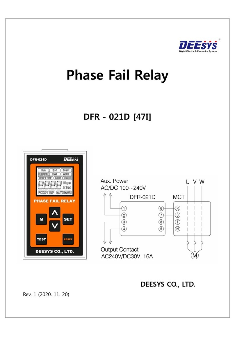
DEMA 400 Series User manual

1
DPM 400 D
DIRECTIONAL PROTECTION RELAY
USER GUIDE

2
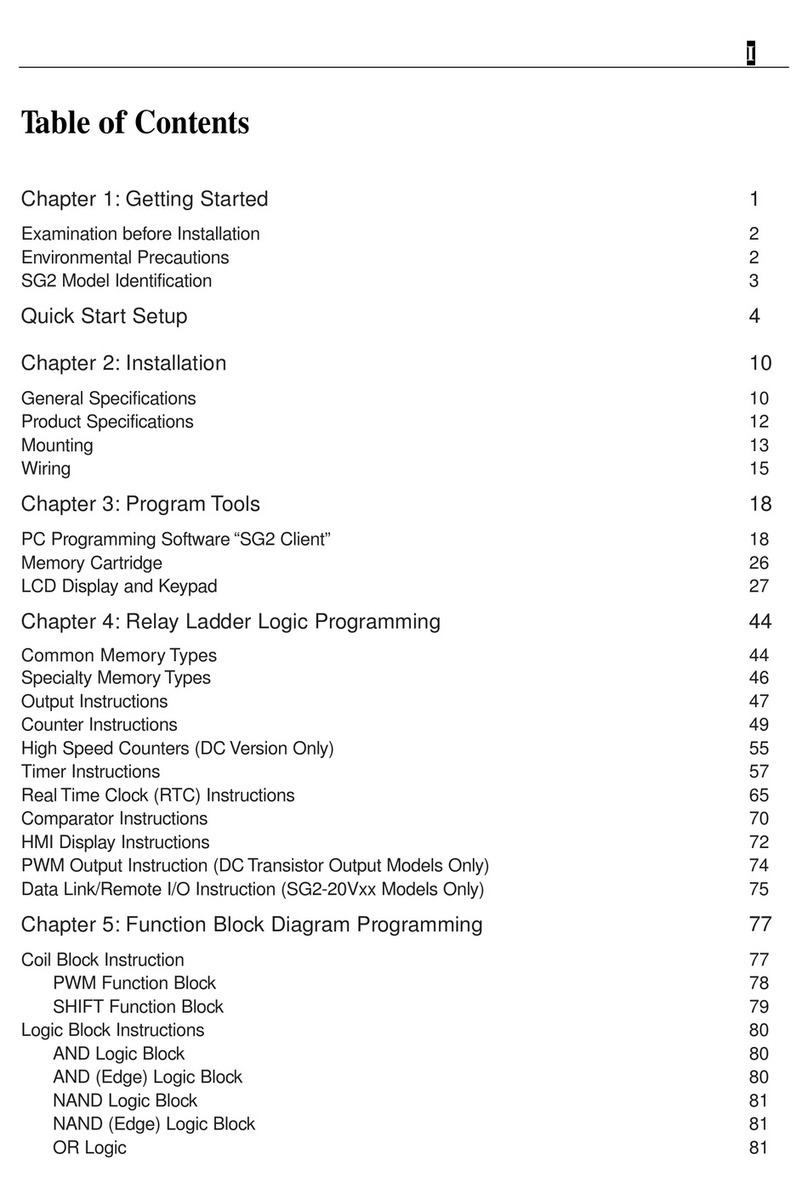
I. Index
I. Index .......................................................................................................................... 2
1. Introduction.............................................................................................................. 16
2. General Characteristics of 400 Series Relays.......................................................... 16
General Features of 400 Series Relays..................................................................................... 19
3. Physical Properties of 400 Series Relays................................................................. 20
3.1 Case..................................................................................................................... 20
3.2 ............................................................................................. 20
3.3 ............................................................................................. 20
3.4 Trip LED............................................................................................................. 20
3.5 Alarm LED.......................................................................................................... 20
3.6 Power LED......................................................................................................... 21
3.7 Internal Error LED............................................................................................. 21
3.8 Ethernet Port ...................................................................................................... 21
3.10 ............................................................................................... 21
3.11 Multifunctional Buttons ................................................................................................. 21
3.12 Internal Unit Lock.......................................................................................................... 21
3.13 Reset Button..................................................................................................................... 21
3.14 IP52 Reset Button............................................................................................................. 21
3.15 Device Label .................................................................................................................... 22
3.16 Case Earthing Screw ........................................................................................................ 22
3.17 Terminal Blocks............................................................................................................... 22
3.18 Special Coating Case........................................................................................................ 22
3.19 Circuit Diagram................................................................................................................ 23
3.20 Internal Unit ..................................................................................................................... 23
3.21 Mounting Screws for the Cover ....................................................................................... 23
3.22 Internal Unit Tracks ......................................................................................................... 23
3.23 Case Earthing Continuity Contact.................................................................................... 24
3.24 Faraday Cage.................................................................................................................... 24
3.25 Unit Terminal Blocks....................................................................................................... 25
3.26 Internal Unit Tracks ......................................................................................................... 25
3.27 Internal Unit Locking Mechanism ................................................................................... 25
3.28 Internal Unit Lock Handle and Release Trigger .............................................................. 25

3
3.29 Lock Button...................................................................................................................... 25
3.30 Mounting Screws for the Cover ....................................................................................... 26
3.31 Terminal Plugs ................................................................................................................. 26
3.32 Lock Pivot ........................................................................................................................ 26
3.33 Mounting Holes................................................................................................................ 26
4. Main Menu............................................................................................................... 27
4.1 Informations........................................................................................................ 28
4.2 Measurements ..................................................................................................... 28
4.2.1 Input Monitoring-------------------------------------------------------------------------30
4.2.2 Output Relay Monitoring----------------------------------------------------------------30
4.2.3 All Fundamental Measurements-------------------------------------------------------31
4.2.4 All RMS Measurements -----------------------------------------------------------------32
4.2.5 RMS Currents ----------------------------------------------------------------------------33
4.2.6 Phase-Neutral Voltages -----------------------------------------------------------------33
4.2.7 Phase-Phase Voltages -------------------------------------------------------------------34
4.2.8 I0 - I1 - I2-----------------------------------------------------------------------------------34
4.2.9 V0- V1- V2--------------------------------------------------------------------------------35
4.2.10 Thermal Overload ------------------------------------------------------------------------35
4.2.11 Power Measurements --------------------------------------------------------------------36
4.2.12 LED States--------------------------------------------------------------------------------37
4.2.13 Current Breaker Monitoring ------------------------------------------------------------37
4.2.14 Instant Max Currents---------------------------------------------------------------------38
4.2.15 Demand Measurements -----------------------------------------------------------------39
4.2.16 Energy-------------------------------------------------------------------------------------39
4.2.17 Analog mA Input ------------------------------------------------------------------------40
4.3 Protection Settings ............................................................................................. 40
4.3.1 Protection and Reset Curves -----------------------------------------------------------42
4.3.1.1 IEC Inverse Time Protection Curves......................................................................43
4.3.1.2 IEC Thermal Overload Protection Curves...............................................................45
4.3.1.3 ANSI / IEEE Inverse Time Protection Curves ........................................................47
4.3.1.4 Custom Protection Curves.......................................................................................48
4.3.1.4.1 Definite Time Protection and Reset Delays ( DMT ).............................51
4.3.1.4.2 Inverse Definite Time Reset Curves ( IDMT )......................................52
4.3.2 Current Protection Settings-------------------------------------------------------------53
4.3.2.1 50/51P Phase Overcurrent Protection...................................................................54

4
4.3.2.1.1 Protection................................................................................................55
4.3.2.1.2 Start Value.............................................................................................55
4.3.2.1.3 Delay Type .............................................................................................55
4.3.2.1. 4 Operate Delay......................................................................................55
4.3.2.1.5 TMS.......................................................................................................55
4.3.2.1.6 Reset Type..............................................................................................55
4.3.2.1.7 Reset Delay............................................................................................56
4.3.2.1.8 Measurement Mode...............................................................................56
4.3.2.2 Earth Overcurrent Protection..................................................................................56
4.3.2.2.1 Protection................................................................................................57
4.3.2.2.2 Start Value..............................................................................................58
4.3.2.2.3 Delay Type .............................................................................................58
4.3.2.2.4 Operate Delay........................................................................................58
4.3.2.2.5 TMS.......................................................................................................58
4.3.2.2.6 Reset Type.............................................................................................58
4.3.2.2.7 Reset Delay............................................................................................59
4.3.2.2.8 RTMS ....................................................................................................59
4.3.2.2.9 Measurement Mode...............................................................................59
4.3.2.3 49 Thermal Overload Protection .........................................................................59
4.3.2.3.1 Protection................................................................................................60
4.3.2.3.2 I>...........................................................................................................60
4.3.2.3.3 Te.............................................................................................................61
4.3.2.3.4 k.............................................................................................................61
4.3.2.3.5 .....................................................................................................61
4.3.2.3.6 Alarm......................................................................................................61
4.3.2.3.7 ..................................................................................................62
4.3.2.3.8 ...................................................................................................62
4.3.2.4 67P Directional Phase Overcurent Protection ......................................................62
4.3.2.4.1 Protection...............................................................................................63
4.3.2.4.2 Start Value.............................................................................................64
4.3.2.4.3 Delay Type ............................................................................................64
4.3.2.4.4 Operate Delay.........................................................................................64
4.3.2.4.5 TMS.......................................................................................................64
4.3.2.4.6 Reset Type.............................................................................................64
4.3.2.4.7 Reset Delay............................................................................................65

5
4.3.2.4.8 RTMS .....................................................................................................65
4.3.2.4.9 Trip Zone................................................................................................65
4.3.2.4.10 Torque Angle..........................................................................................65
4.3.2.4.11 Direction Mode.......................................................................................65
4.3.2.4.12 Measurement Mode...............................................................................66
4.3.2.5 67N Directional Earth Overcurrent Protection....................................................66
4.3.2.5.1 Protection...............................................................................................67
4.3.2.5.2 Start Value.............................................................................................67
4.3.2.5.3 U0Start Value........................................................................................67
4.3.2.5.4 Delay Type ............................................................................................67
4.3.2.5.5 Operate Delay.........................................................................................68
4.3.2.5.6 TMS.......................................................................................................68
4.3.2.5.7 Reset Type..............................................................................................68
4.3.2.5.8 Reset Delay.............................................................................................68
4.3.2.5.9 RTMS .....................................................................................................69
4.3.2.5.10 Trip Zone..............................................................................................69
4.3.2.5.11 Torque Angle..........................................................................................69
4.3.2.5.12 Direction Mode.......................................................................................69
4.3.2.5.13 Measurement Mode...............................................................................69
4.3.2.6 37P Phase Undercurrent Protection........................................................................69
4.3.2.6.1 Protection...............................................................................................70
4.3.2.6.2 Start Value.............................................................................................71
4.3.2.6.3 Operate Delay........................................................................................71
4.3.2.6.4 Reset Delay............................................................................................71
4.3.2.6.5 Inhibit on 52A.........................................................................................71
4.3.2.6.6 Inhibit on U< .........................................................................................71
4.3.2.6.7 U< Locking Level..................................................................................71
4.3.2.6.8 Measurement Mode................................................................................71
4.3.2.7 46-Negative Sequence Overcurrent Protection.......................................................72
4.3.2.7.1 Protection...............................................................................................73
4.3.2.7.2 Start Value..............................................................................................73
4.3.2.7.3 Delay Type .............................................................................................73
4.3.2.7.4 Operate Delay.........................................................................................73
4.3.2.7.5 TMS.......................................................................................................73
4.3.2.7.6 Reset Type.............................................................................................73

6
4.3.2.7.7 Reset Delay.............................................................................................74
4.3.2.7.8 RTMS ....................................................................................................74
4.3.3 Voltage Protection Settings ------------------------------------------------------------74
4.3.3.1 59 Over voltage Protection..................................................................................75
4.3.3.1.1 Protection................................................................................................76
4.3.3.1.2 Start Value..............................................................................................76
4.3.3.1.3 Operate Delay........................................................................................76
4.3.3.1.4 Reset Delay............................................................................................76
4.3.3.1.5 Hysteresis...............................................................................................77
4.3.3.1.6 Measurement Mode...............................................................................77
4.3.3.1.7 Phase Operation Mode............................................................................77
4.3.3.2 27- Under Voltage Protection.................................................................................77
4.3.3.2.1 Protection...............................................................................................79
4.3.3.2.1 Start Value..............................................................................................79
4.3.3.2.3 Operate Delay.........................................................................................79
4.3.3.2.4 Reset Delay............................................................................................79
4.3.3.2.5 Inhibit on U< .........................................................................................79
4.3.3.2.6 U< Locking Level..................................................................................79
4.3.3.2.7 Hysteresis...............................................................................................80
4.3.3.2.8 Measurement Mode................................................................................80
4.3.3.2.9 Phase Operation Mode............................................................................80
4.3.3.3 47 Negative Sequence Over Voltage Protection ...................................................80
4.3.3.3.1 Protection...............................................................................................81
4.3.3.3.2 Start Value.............................................................................................81
4.3.3.3.3 Operate Delay.........................................................................................81
4.3.3.3.4 Reset Delay............................................................................................81
4.3.3.3.5 Hysteresis...............................................................................................82
4.3.3.4 59N Notr Over Voltage Protection......................................................................82
4.3.3.4.1 Protection...............................................................................................83
4.3.3.4.2 Start Value..............................................................................................83
4.3.3.4.3 Operate Delay.........................................................................................83
4.3.3.4.4 Reset Delay............................................................................................83
4.3.3.4.5 Hysteresis................................................................................................84
4.3.4 Frequency Protection Settings----------------------------------------------------------84
4.3.4.1 81U Under Frequency Protection.........................................................................85

7
4.3.4.1.1 Protection...............................................................................................86
4.3.4.1.2 Start Value.............................................................................................86
4.3.4.1.3 Operate Delay.........................................................................................86
4.3.4.1.4 Reset Delay............................................................................................86
4.3.4.1.5 Hysteresis...............................................................................................87
4.3.4.2 81O Over Frequency Protection..........................................................................87
4.3.4.2.1 Protection................................................................................................88
4.3.4.2.2 Start Value..............................................................................................88
4.3.4.2.3 Operate Delay.........................................................................................88
4.3.4.2.4 Reset Delay............................................................................................88
4.3.4.2.5 Hysteresis................................................................................................89
4.3.4.3 81R Rate of Change of Frequency Protection.....................................................89
4.3.4.3.1 Protection................................................................................................90
4.3.4.3.2 Start Value..............................................................................................90
4.3.4.3.3 Operate Delay........................................................................................91
4.3.4.3.4 Reset Delay............................................................................................91
4.3.5 Power Protection Settings---------------------------------------------------------------91
4.3.5.1 32OP Directional Active Over Power .................................................................92
4.3.5.1.1 Protection................................................................................................93
4.3.5.1.2 Start Value..............................................................................................93
4.3.5.1.3 Direction Angle .....................................................................................94
4.3.5.1.4 Operate Delay.........................................................................................94
4.3.5.1.5 Reset Delay............................................................................................94
4.3.5.1.6 Hysteresis...............................................................................................94
4.3.5.2 32UP Directional Active Under Power ................................................................94
4.3.5.2.1 Protection................................................................................................95
4.3.5.2.2 Start Value..............................................................................................95
4.3.5.2.3 Direction Angle .....................................................................................96
4.3.5.2.4 Operate Delay.........................................................................................96
4.3.5.2.5 Reset Delay............................................................................................96
4.3.5.2.6 Inhibit on P<...........................................................................................96
4.3.5.2.7 P< Locking Level ...................................................................................96
4.3.5.2.8 Hysteresis...............................................................................................96
4.3.5.3 32OQ Directional Reactive Over Power 133 ......................................................97
4.3.5.3.1 Protection...............................................................................................97

8
4.3.5.3.2 Start Value..............................................................................................98
4.3.5.3.3 Direction Angle ......................................................................................98
4.3.5.3.4 Operate Delay.........................................................................................98
4.3.5.3.5 Reset Delay............................................................................................98
4.3.5.3.6 Hysteresis................................................................................................98
4.3.5.4 32UQ Directional Reactive Under Power ...........................................................98
4.3.5.4.1 Protection...............................................................................................99
4.3.5.4.2 Start Value.............................................................................................99
4.3.5.4.3 Direction Angle ...................................................................................100
4.3.5.4.4 Operate Delay.......................................................................................100
4.3.5.4.5 Reset Delay...........................................................................................100
4.3.5.4.6 Inhibit on Q< .......................................................................................100
4.3.5.4.7 Q< Locking Level.................................................................................100
4.3.5.4.8 Hysteresis..............................................................................................100
4.3.5.5 32N Wattmetric Earth Protection ......................................................................101
4.3.5.5.1 Protection.............................................................................................102
4.3.5.5.2 Start Value...........................................................................................102
4.3.5.5.3 Delay Type ...........................................................................................102
4.3.5.5.4 Operate Delay.......................................................................................102
4.3.5.5.5 Reset Type............................................................................................102
4.3.5.5.6 Reset Delay...........................................................................................102
4.3.5.5.7 Hysteresis..............................................................................................103
4.3.6 General Protection Settings ----------------------------------------------------------- 103
4.3.6.1 Pe-Iecos Protection...............................................................................................103
4.3.6.1.1 Mod.......................................................................................................103
4.3.6.1.2 RCA.....................................................................................................103
4.3.6.2 Frequency Protection.............................................................................................103
4.3.6.2.1 Block U.................................................................................................103
4.3.6.2.2 Number of Cycles................................................................................103
4.3.6.2.3 Number of Valid.................................................................................104
4.3.6.2.4 Inhibit>20 Hz/s....................................................................................104
4.4 Automatic control ............................................................................................. 104
4.4.1 46BC Broken Conductor------------------------------------------------------------ 104
4.4.2 94/86 Output / Relay Trip Setting ------------------------------------------------- 104
4.4.3 Trip Settings----------------------------------------------------------------------------- 104

9
4.4.4 Output Settings----------------------------------------------------------------------------------- 104
4.4.5 Input Settings---------------------------------------------------------------------------- 104
4.4.6 Custom Input / Timer Relay ---------------------------------------------------------- 104
4.4.7 Cold Load Pickup ---------------------------------------------------------------------- 105
4.4.8 Blocking Selectivity Settings --------------------------------------------------------- 105
4.4.9 68 Inrush Blocking-------------------------------------------------------------------- 105
4.4.10 Delaying Logic Selectivity Setttings ------------------------------------------------ 105
4.4.11 51V Voltage Controlled Overcurrent---------------------------------------------- 105
4.4.12 VT Supervision ------------------------------------------------------------------------- 105
4.4.13 CT Supervision ------------------------------------------------------------------------- 105
4.4.14 Circuit Breaker Failure ---------------------------------------------------------------- 105
4.4.15 Circuit Breaker Supervision----------------------------------------------------------- 105
4.4.16 Trip Circuit Supervision--------------------------------------------------------------- 105
4.4.17 Logical Equations ---------------------------------------------------------------------- 105
4.5 System settings................................................................................................................. 106
4.5.1 Language------------------------------------------------------------------------------------------ 106
4.5.2 Function Symbol--------------------------------------------------------------------------------- 107
4.5.3 Date-Time----------------------------------------------------------------------------------------- 108
4.5.4 Bay Name-------------------------------------------------------------------------------- 108
4.5.5 Device Name---------------------------------------------------------------------------- 108
4.5.6 Nominal Frekans----------------------------------------------------------------------- 108
4.5.7 LCD Lighting Time ------------------------------------------------------------------- 109
4.5.8 Default Screen-------------------------------------------------------------------------- 109
4.5.9 Default Screen Timeout --------------------------------------------------------------- 109
4.5.10 Main Screen Measurement------------------------------------------------------------ 110
4.6 Configuration ................................................................................................... 110
4.6.1 General Options------------------------------------------------------------------------- 111
4.6.2 Measurement Settings----------------------------------------------------------------- 112
4.6.3 Disturbance Recoding----------------------------------------------------------------- 112
4.6.4 Time Synchronization ----------------------------------------------------------------- 113
4.6.5 CT / VT Settings------------------------------------------------------------------------ 113
4.6.11 Alarm Settings ------------------------------------------------------------------------- 115
4.6.12 Communication Settings -------------------------------------------------------------- 116
4.6.13 Ethernet Interface Settings ------------------------------------------------------------ 116
4.7 Recordings ........................................................................................................ 117

10
4.8 Order Menu....................................................................................................... 117
4.9 Active Functions............................................................................................... 118
4.10 Function Test..................................................................................................... 118
4.11 Authorization ................................................................................................... 118

11
Introduction
400 series protection relays are the product of the combination of DEMA Relay's field
experience from 1977 to today with today's technology.
The 400 series protection relays have successfully passed the tests that carried out in the
accredited KEMA laboratories performing international standards tests and proved themselves
in this field.
This guide mentions about physical and general characteristics of the 400 series protection
relays along with protection functions, working principles of these functions, supported
communication protocols, automatic protection and configuration settings.
IEC61850, IEC60617 Symbols and IEE-ANSI Codes

12
IEC61850
IEC60617
IEEE-ANSI
TRIP
TRIP
TRIP
CB CLOSE
CB CLOSE
CB CLOSE
WATCHDOG
WATCHDOG
WATCHDOG
PH_PTOC_1
tI>
50/51P-1
PH_PTOC_2
tI>>
50/51P-2
PH_PTOC_3
tI>>>
50/51P-3
PHI_PIOC_1
I>
50/51P-I-1
PHI_PIOC_2
I>>
50/51P-I-2
PHI_PIOC_3
I>>>
50/51P-I-3
E_PTOC_1
tIe>
50/51N-1
E_PTOC_2
tIe>>
50/51N-2
E_PTOC_3
tIe>>>
50/51N-3
ED_PTOC_1
tIe_d>
50/51N-D-1
ED_PTOC_2
tIe_d>>
50/51N-D-2
EI_PIOC_1
Ie>
50/51N-I-1
EI_PIOC_2
Ie>>
50/51N-I-2
EI_PIOC_3
Ie>>>
50/51N-I-3
EDI_PIOC_1
Ie_d>
50/51N-DI-1
EDI_PIOC_2
Ie_d>>
50/51N-DI-2
NS_PTOC_1
tI2>
46-1
NS_PTOC_2
tI2>>
46-2
NS_PTOC_3
tI2>>>
46-3
NSI_PIOC_1
I2>
46-I-1
NSI_PIOC_2
I2>>
46-I-2
NSI_PIOC_3
I2>>>
46-I-3
DPH_PTOC_1
tI> ->
67P-1
DPH_PTOC_2
tI>> ->
67P-2
DPH_PTOC_3
tI>>> ->
67P-3
DPHI_PTOC_1
I> ->
67P-I-1
DPHI_PTOC_2
I>> ->
67P-I-2
DPHI_PTOC_3
I>>> ->
67P-I-3
DE_PTOC_1
tIe> ->
67N-1
DE_PTOC_2
tIe>> ->
67N-2
DE_PTOC_3
tIe>>> ->
67N-3
DED_PTOC_1
tIe_d> ->
67N-D-1
DED_PTOC_2
tIe_d>> ->
67N-D-2
DEI_PTOC_1
Ie> ->
67N-I-1
DEI_PTOC_2
Ie>> ->
67N-I-2
DEI_PTOC_3
Ie>>> ->
67N-I-3
DEDI_PTOC_1
Ie_d> ->
67N-DI-1
DEDI_PTOC_2
Ie_d>> ->
67N-DI-2
PH_PTTR
49
PH_PTTR_A
-A
49-A
PH_PTUC
tI<
37P
PHI_PIUC
I<
37P-I
PH_PTOV_1
tU>
59-1
PH_PTOV_2
tU>>
59-2

13
PHI_PIOV_1
U>
59-I-1
PHI_PIOV_2
U>>
59-I-2
PH_PTUV_1
tU<
27-1
PH_PTUV_2
tU<<
27-2
PHI_PIUV_1
U<
27-I-1
PHI_PIUV_2
U<<
27-I-2
NS_PTOV_1
tU2>
47-1
NSI_PIOV_1
U2>
47-I-1
E_PTOV_1
tUe>
59N-1
EI_PIOV_1
Ue>
59N-I-1
PTUF_1
tf<
81U-1
PTUF_2
tf<<
81U-2
PTUF_3
tf<<<
81U-3
PTUF_4
tf<<<<
81U-4
PTUF_5
tf<<<<<
81U-5
PTUF_6
tf<<<<<<
81U-6
PIUF_1
f<
81U-I-1
PIUF_2
f<<
81U-I-2
PIUF_3
f<<<
81U-I-3
PIUF_4
f<<<<
81U-I-4
PIUF_5
f<<<<<
81U-I-5
PIUF_6
f<<<<<<
81U-I-6
PTOF_1
tf>
81O-1
PTOF_2
tf>>
81O-2
PTOF_3
tf>>>
81O-3
PTOF_4
tf>>>>
81O-4
PTOF_5
tf>>>>>
81O-5
PTOF_6
tf>>>>>>
81O-6
PIOF_1
f>
81O-I-1
PIOF_2
f>>
81O-I-2
PIOF_3
f>>>
81O-I-3
PIOF_4
f>>>>
81O-I-4
PIOF_5
f>>>>>
81O-I-5
PIOF_6
f>>>>>>
81O-I-6
PFRC_1
t(df/dt)>
81R-1
PFRC_2
t(df/dt)>>
81R-2
PFRC_3
t(df/dt)>>>
81R-3
PFRC_4
t(df/dt)>>>>
81R-4
PFRC_5
t(df/dt)>>>>>
81R-5
PFRC_6
t(df/dt)>>>>>>
81R-6
I_PFRC_1
(df/dt)>
81R-I-1
I_PFRC_2
(df/dt)>>
81R-I-2
I_PFRC_3
(df/dt)>>>
81R-I-3
I_PFRC_4
(df/dt)>>>>
81R-I-4
I_PFRC_5
(df/dt)>>>>>
81R-I-5
I_PFRC_6
(df/dt)>>>>>>
81R-I-6
P_PDOP_1
tP>
32OP-1
P_PDOP_2
tP>>
32OP-2

14
PI_PDOP_1
P>
32OP-I-1
PI_PDOP_2
P>>
32OP-I-2
P_PDUP_1
tP<
32UP-1
P_PDUP_2
tP<<
32UP-2
PI_PDUP_1
P<
32UP-I-1
PI_PDUP_2
P<<
32UP-I-2
Q_PDOP_1
tQ>
32OQ-1
Q_PDOP_2
tQ>>
32OQ-2
QI_PDOP_1
Q>
32OQ-I-1
QI_PDOP_2
Q>>
32OQ-I-2
Q_PDUP_1
tQ<
32UQ-1
Q_PDUP_2
tQ<<
32UQ-2
QI_PDUP_1
Q<
32UQ-I-1
QI_PDUP_2
Q<<
32UQ-I-2
P_PSDE_1
tPe>
32N-1
P_PSDE_2
tPe>>
32N-2
PI_PSDE_1
Pe>
32N-I-1
PI_PSDE_2
Pe>>
32N-I-2
RREC_RUN
ARC_RUN
79_RUN
RREC_TRIP
ARC_TRIP
79_TRIP
RREC_INTLOCK
ARC_INTLOCK
79_INTLOCK
RREC_EXTLOCK
ARC_EXTLOCK
79_EXTLOCK
TIM_GAPC1
tAux-1
tAux-1
TIM_GAPC2
tAux-2
tAux-2
TIM_GAPC3
tAux-3
tAux-3
TIM_GAPC4
tAux-4
tAux-4
TIM_GAPC5
tAux-5
tAux-5
TIM_GAPC6
tAux-6
tAux-6
TIM_GAPC7
tAux-7
tAux-7
TIM_GAPC8
tAux-8
tAux-8
TIM_GAPC1_start
tAux-1_start
tAux-1_start
TIM_GAPC2_start
tAux-2_start
tAux-2_start
TIM_GAPC3_start
tAux-3_start
tAux-3_start
TIM_GAPC4_start
tAux-4_start
tAux-4_start
TIM_GAPC5_start
tAux-5_start
tAux-5_start
TIM_GAPC6_start
tAux-6_start
tAux-6_start
TIM_GAPC7_start
tAux-7_start
tAux-7_start
TIM_GAPC8_start
tAux-8_start
tAux-8_start
BC_PTOC
t%(I2/I1)>
46BC
BCI_PIOC
%(I2/I1)>
46BC_I
CB_RBRF
I<BF
50BF
CBS_SCBR
CB_SUP
CB_SUP
CTS
CTS
74CT
EQU_GAPC1
LOG_EQ_1
LOG_EQ_1
EQU_GAPC2
LOG_EQ_2
LOG_EQ_2
EQU_GAPC3
LOG_EQ_3
LOG_EQ_3
EQU_GAPC4
LOG_EQ_4
LOG_EQ_4
EQU_GAPC5
LOG_EQ_5
LOG_EQ_5

15
EQU_GAPC6
LOG_EQ_6
LOG_EQ_6
EQU_GAPC7
LOG_EQ_7
LOG_EQ_7
EQU_GAPC8
LOG_EQ_8
LOG_EQ_8
EQU_GAPC1_str
LOG_EQ_1_str
LOG_EQ_1_str
EQU_GAPC2_str
LOG_EQ_2_str
LOG_EQ_2_str
EQU_GAPC3_str
LOG_EQ_3_str
LOG_EQ_3_str
EQU_GAPC4_str
LOG_EQ_4_str
LOG_EQ_4_str
EQU_GAPC5_str
LOG_EQ_5_str
LOG_EQ_5_str
EQU_GAPC6_str
LOG_EQ_6_str
LOG_EQ_6_str
EQU_GAPC7_str
LOG_EQ_7_str
LOG_EQ_7_str
EQU_GAPC8_str
LOG_EQ_8_str
LOG_EQ_8_str
SOTF
SOTF
SOTF
TCS_SCBR
TCS
TCS
VTS
VTS
74VT
MANUAL TRIP
MANUAL TRIP
MANUAL
TRIP
REMOTE TRIP
REMOTE TRIP
REMOTE TRIP
INPUT TRIP
INPUT TRIP
INPUT TRIP
MANUAL
CLOSE
MANUAL
CLOSE
MANUAL
CLOSE
REMOTE CLOSE
REMOTE
CLOSE
REMOTE
CLOSE
INPUT CLOSE
INPUT CLOSE
INPUT CLOSE
AIN_TRIP
AIN_TRIP
AIN_TRIP
AIN_ALARM
AIN_ALARM
AIN_ALARM
AIN_LOW1
AIN_LOW1
AIN_LOW1
AIN_LOW2
AIN_LOW2
AIN_LOW2
AIN_DELTA
AIN_DELTA
AIN_DELTA
AIN_ERROR
AIN_ERROR
AIN_ERROR

16
Introduction
In this technical manual, the protection functions of the DEMA 400 series relays and their
application methods are given.
The manual provides control of the device connection and energization of the device,
parameter settings and configuration procedures according to the field requirements.
General Characteristics of 400 Series Relays
The DEMA 400 Series is a series of multifunctional modern digital protection relays with
voltage, overcurrent, directional overcurrent and motor protection versions. Electronic,
physical and functional structure, technology and standards represent the last point; It
provides all users with an important option for modern secondary protection systems with the
convenience and advantages they provide in installation, commissioning and operation.
DEMA 400 Series Digital Overcurrent Protection Relays have successfully completed all type
tests in the internationally accredited test labs, which are required by the relevant articles of
IEC 60255, IEC 60529, IEC 60695, IEC 60068 and IEC 61850 standards, ISO 9001: 2008
quality assurance system under the guarantee of users.
The 400 Series relays, which began production in 2017, show their high performance in many
applications; It is still successfully used in many areas including organized industrial zones,
medium and large production facilities, transmission and distribution centers.

17
MPM 400 D DPM 400
Motor Protection relay Directional Protection
Relay
CPM 400 D VPM 400 D
Over Current Protection Relay Voltage & Frequency
protction Relay
Digital Protection Relays

18
400 Series Protection Relays and General Features

19
General Features of 400 Series Relays
•Auxiliary supply voltage compatibility with all voltages in the field: (24 240) Vac /
Vdc, operational range: (22 275) Vac / Vdc.
•Operational ambient temperature range: (-
•Windows 32/64-bit based PC control software,
•Wide communication protocols support: IEC 61850 + GOOSE, IEC 60870-5-103,
DNP 3.0, MODBUS RTU and TCP,
•Wide IEC, ANSI and custom delay curve support, enabling selectivity setup with all
types of protection relays including electromechanical relays,
•3- 300
VAC insulation withstand,
•4-channel X/1 A and X/5 A current input with continuous 20 A and 1 s 500 A
thermal withstand, DMT and IDMT delay curve support for all current & voltage
protection functions,
•Option for RMS or fundamental harmonics measurement method for various
protection functions
•Remote control and monitoring of the circuit breaker via dedicated menu with mimic
diagram,
•Annunciating functions and 8/10 optically coupled programmable digital inputs that
eliminate the need to use external annunciators (e.g. to evaluate Buchholz, temperature
and pressure signals), 8 programmable 8 A 250 V outputs (4 SPDT + 4 SPST),
•Full screen multimeter display, measurement functions that eliminate the need to use
double core CTs and external meters,
•Built-in X/1 A and X/5 A current transformer compatibility,
•Super-capacitor fed real-time clock,
•8 independent settings groups,
•3-stage security password system,
•IP52 front side and IP20 backside environmental protection,
•Fast and low cost repairs thanks to the modular electronics,
•3-year limited warranty, Matchless customer support, a variety of application schemas
and technical documents.

20
Physical Properties of 400 Series Relays
3.1 Case
The 400 Series case is made of a special alloy in stainless steel. It is covered with modern
PVC coating technique. The terminal blocks are fixed to the rear of the box.
3.2 “Phase Fault” LED
functions. The Trip LED runs continuously as long as the trip contact is in closed position,
while flashing until reset if the CB is tripped by the relay and the disturbance is cleared.
3.3 “Earth Fault” LED
3.4 Trip LED
Trip LED indicates trip operations triggered by any of the active protection functions. LED
3.5 Alarm LED
Alarm LED indicates abnormal states of the protected circuits, and is triggered by any of the
active alarming functions. LED behaviour is configurable.
This manual suits for next models
5
Table of contents
Other DEMA Relay manuals
