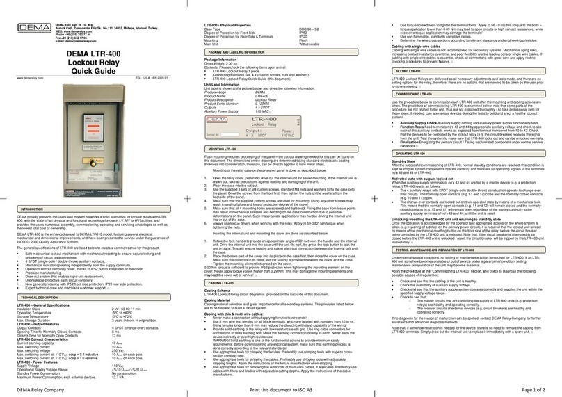
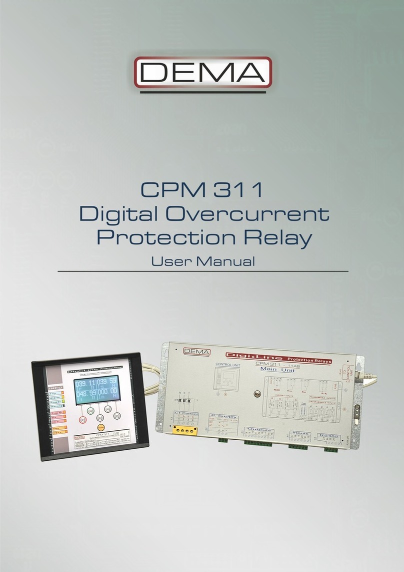
DEMA CPM 310 G User manual

CPM 310 G
Digital Overcurrent
Protection Relay
User & Application Manual vEN.2016.03

- 2 -

- 3 -
Index
1. About DEMA p.6
1.1. General Information p.7
1.2. Product Range p.9
1.3. Contact Us p.10
2. Introduction p.11
2.1. General Specifications & Advantages p.12
2.2. Physical Introduction p.14
2.3. Protection and Reset Curves p.22
2.3.1. IEC Protection Curves p.23
2.3.2. IEC Thermal Overload Protection Curve p.25
2.3.3. ANSI / IEEE Protection Curves p.26
2.3.4. Custom Protection Curves p.28
2.3.5. DMT: Definite Minimum Time Characteristic p.30
2.3.6. RIDMT: Reset Inverse Definite Minimum Time Characteristics p.31
3. Packing & Labeling Information p.32
4. Operating Manual p.34
4.1. General Principles p.35
4.2. Mounting p.36
4.2.1. Panel Cut-out p.36
4.2.2. Mounting the Case p.37
4.2.3. Mounting the Inner Unit and the Cover p.37
4.3. Cabling p.38
4.3.1. Cabling Diagram p.38
4.3.2. Cabling Material p.42
4.4. Setting p.43
4.4.1. Example Setting and Calculation p.44
4.4.2. Dip-switch Settings p.47
4.4.3. Example Dip-switch Settings p.49
4.4.4. Warnings p.49
4.5. Commissioning p.50
4.6. Operating p.51
4.6.1. Normal Operation p.51
4.6.2. Fault Diagnosis and Maintenance p.51
4.6.3. Recommissioning p.51
4.7. Testing & Maintenance & Reparation p.52
5. Relay Menus Manual p.53
5.1. Introduction p.54
5.2. The Menu Tree p.55
5.3. Reset Menu p.62
5.4. Circuit Breaker Monitoring and Control Menu p.64
5.5. Settings Group Selection Menu p.65
5.6. Protection and Control Settings Menu p.66
5.6.1. I> Phase Overcurrent 1st Threshold Protection Menu p.67
5.6.2. I>> Phase Overcurrent 2nd Threshold Protection Menu p.68
5.6.3. I>>> Phase Overcurrent 3rd Threshold Protection Menu p.69
5.6.4. Ie> Earth Overcurrent 1st Threshold Protection Menu p.70
5.6.5. Ie>> Earth Overcurrent 2nd Threshold Protection Menu p.71
5.6.6. Ie>>> Earth Overcurrent 3rd Threshold Protection Menu p.72
5.6.7. I2> Negative Sequence Overcurrent 1st Threshold Protection Menu p.73

- 4 -
5.6.8. I2>> Negative Sequence Overcurrent 2nd Threshold Protection Menu p.74
5.6.9. %(I2/I1)> Broken Conductor Protection Menu p.75
5.6.10. I< Phase Undercurrent Protection Menu p.76
5.6.11. IΘ> Thermal Overload Protection Menu p.77
5.6.12. Auto-recloser Settings Menu p.80
5.7. Main Menu p.83
5.7.1. Measurement Menu p.85
5.7.1.1. RMS Current and Frequency Measurements Menu p.86
5.7.1.2. Max RMS Current Measurements Menu p.87
5.7.1.3. Fundamental Harmonics Measurements Menu p.88
5.7.1.4. Positive and Negative Sequence Current Measurements Menu p.89
5.7.1.5. Thermal Θ Measurements Menu p.90
5.7.1.6. Input & Output Status Monitoring Menu p.91
5.7.1.7. Circuit Breaker Measurements p.92
5.7.1.8. Auto-recloser (ARCL) Measurements Menu p.93
5.7.1.9. LED Status Menu p.94
5.7.2. Communication Settings Menu p.95
5.7.3. Event Records Menu p.96
5.7.4. System Settings Menu p.97
5.7.5. Current Transformer Settings Menu p.100
5.7.6. Automatic Control Settings Menu p.102
5.7.6.1. Cold Load Pickup Settings Menu p.103
5.7.6.2. Output Relay Settings Menu p.105
5.7.6.3. Trip Settings Menu p.106
5.7.6.4. Input Settings Menu p.107
5.7.6.5. Blocking Logic Selectivity Settings Menu p.108
5.7.6.6. Circuit Breaker Failure Recognition Settings Menu p.111
5.7.6.7. Auxiliary Timer Settings Menu p.113
5.7.6.8. Delaying Logic Selectivity Settings Menu p.114
5.7.6.9. Auto-recloser (ARCL) Settings Menu p.115
5.7.6.10. CB Supervision Settings Menu p.118
5.7.6.11. Programmable LEDs Settings Menu p.121
5.7.6.12. Latching Settings Menu p.123
5.7.6.13. Alarm Settings Menu p.125
5.7.7. Function Test Menu p.126
5.7.8. Fault Records Menu p.127
6. DigiConnect PC Program Manual p.128
6.1. Operating System & Hardware Requirements p.129
6.2. Program Setup p.130
6.3. Program Startup p.133
6.4. Software Introduction and Guide p.136
6.4.1. Welcome Screen p.137
6.4.2. Measurements p.138
6.4.2.1. Analog Values p.138
6.4.2.1.1. RMS Current p.138
6.4.2.1.2. Fundamental Harmonics p.139
6.4.2.1.3. P/N Sequences p.140
6.4.2.1.4. Max. RMS Current p.141
6.4.2.2. Circuit Breaker Measurements p.142
6.4.2.3. ARCL Measurements p.143
6.4.2.4. Remote Control p.144
6.4.3. Alarms / Event Records Menu p.145
6.4.3.1. Alarms p.145
6.4.3.2. Event Records p.146
6.4.3.3. Trip Records p.147
6.4.4. Settings Menu p.148

- 5 -
6.4.4.1. Protection Settings p.149
6.4.4.1.1. Phase Protection Settings p.151
6.4.4.1.2. Earth Protection Settings p.152
6.4.4.1.3. Broken Conductor Protection Settings p.153
6.4.4.1.4. Negative Sequence Protection Settings p.154
6.4.4.1.5. Thermal (Overload) Protection Settings p.155
6.4.4.2. CT Settings p.156
6.4.4.3. System Settings p.157
6.4.4.4. Automatic Control Settings p.158
6.4.4.4.1. Input Settings p.159
6.4.4.4.2. (Auxiliary) Timer Settings p.160
6.4.4.4.3. Output Relay Settings p.161
6.4.4.4.4. Trip Settings p.162
6.4.4.4.5. Blocking (Logic) Selectivity Settings p.163
6.4.4.4.6. CB Failure Settings p.164
6.4.4.4.7. Delaying (Logic) Selectivity Settings p.165
6.4.4.4.8. Auto Recloser Settings p.166
6.4.4.4.9. Cold Load Pickup Settings p.168
6.4.4.4.10. CB Supervision Settings p.169
6.4.4.4.11. (Programmable) LED Settings p.170
6.4.4.4.12. Latch Settings p.171
6.4.4.4.13. Alarm Settings p.172
6.4.4.5. Communication Settings p.173
6.4.5. Buffer Menu p.174
6.4.6. Disturbance (Waveform) Records Menu p.180
7. Application Diagrams p.189
7.1. On the Use of Application Diagrams p.190
7.2. Sample Application p.190
7.3. Fundamental Cabling Diagram p.193
7.4. Application Diagram No. 1 p.194
7.5. Application Diagram No. 2 p.195
7.6. Application Diagram No. 3 p.196
7.7. Application Diagram No. 4 p.197
7.8. Application Diagram No. 5 p.198
7.9. Application Diagram No. 6 p.199
7.10. Application Diagram No. 7 p.200
7.11. Application Diagram No. 8 p.201
7.12. Application Diagram No. 9 p.202
7.13. Application Diagram No. 10 p.203
8. Technical Diagrams p.204
8.1. USB Connection Cable p.205
8.2. Technical Drawings p.206
8.3. Technical Specifications p.207
8.4. Default Settings p.214
8.5. Type Tests p.218
8.6. Ordering Codes p.219
9. Glossary p.220

- 6 -
ABOUT DEMA

- 7 -
General Information
DEMA Role San. ve Tic. A. S. is a secondary protection relays and
accessories manufacturer carrying out its activities in a plant
with 2000 m² closed area in Maltepe, Istanbul, Turkey.
The plant itself inspires creativity and innovation by its high-
tech infrastructure, laboratory-clean environment and the art
collection it hosts.
DEMA Role San. ve Tic. A. S. has manufactured over 100,000
pieces of protection units since its foundation in 1977, and has
great reputation among its clients.
The innovations history of DEMA is as follows:
1977 - R3AS20E: The first DMT electromechanical overcurrent protection relay in the country,
1985 - R1TA112: The first draw out type electromechanical overcurrent protection relay in the country
with IDMT delay,
1990 - R1SA01: The first draw out type electromechanical earth fault protection relay in the country with
DMT delay,
1990 - R1ST04: The first draw out type electromechanical thermal overload protection relay in the country
with thermal image display,
1997 - MCR Series: The first draw out type electronic overcurrent protection relay series in the country
with DMT and IDMT delay,
1997 - MVR Series: The first draw out type electronic over/undervoltage protection relay series in the
country with DMT and IDMT delay,
2000 - IR1021: Double-flashing annunciator relay with
LEDs,
2006 - CPM Series: The first draw out type DSP-based
digital overcurrent protection relay with digital communication
and LCD display features.
DEMA Role San. ve Tic. A. S. invests more than 10% of its total
revenue into R&D projects, which clearly demonstrates DEMA’s
commitment into innovation.
The R&D philosophy of DEMA focuses particularly on user-
friendliness, assurance of high-quality, reliability and
international standards compliance of its products.
A good example on the outcomes of DEMA’s R&D philosophy is
the innovative features of CPM 310 series digital overcurrent
protection relays –a product which introduced the most user-
friendly interface yet by employing the mobile phone navigation
technology into protection relays era.
Some other innovations are as follows:
The most secure secondary shorting mechanism on the
world yet, which enables under-load replaceability of
overcurrent protection units more safely than ever,
Withdrawable unit locking mechanism,
Employment of high-frequency band measurement
transformers in protection relays.

- 8 -
The molding workshop of DEMA is one of the most advanced
facilities in its sector. The workshop works only for
Prototyping,
Or production molding construction for DEMA products.
The molding workshop hosts
Wire erosion machines,
Through erosion machines,
Erosion drills,
Precision grinders,
And CNC systems worth over 3,000,000 USD of
investment into production precision.
All of the metal, plastic, electro-mechanical and graphical
components used in DEMA’s products are designed, prototyped
and manufactured in the same facility by DEMA engineers and
technicians.
50% of DEMA’s total revenue comes from international sales
with an increasing proportion. DEMA imported to over 10
countries all over the world in 2012.
The innovative and leading policy of DEMA has been recognized
and awarded by many national titles in the past years. DEMA
promises its clients better solution partnership and wider range
of high quality products in the future, just as provided in the
past.

- 9 -
Product Range
1. DSP-based Digital Protection Relays
CPM 310 G Three phase + earth overcurrent protection relay with draw-out system.
CPM 312 Three phase + earth overcurrent protection relay without draw-out system.
T4CH 4 channel PT100 digital thermistor relay.
2. Annunciating System Components
IT1-6 6-windows optical annunciator.
K 101 - A2 Multitone acoustic annunciator.
KR30 Horn Relay.
IR61K-A2 6-windows optical annunciator with relay and horn outputs in draw-out case.
IR101K-A2 10-windows optical annunciator with relay and horn outputs in draw-out case.
IR1021 10-windows double-flashing optical annunciator with relay and horn outputs in
draw-out case.
3. Auxiliary Devices
KAC Capacitor-based auxiliary supply unit.
GKR15 DC auxiliary supply supervision relay.
RY600 Auxiliary relay
ZR20 On-delay auxiliary time relay.
ZR25 Off-delay auxiliary time relay.
BR25 Flash relay
WR25 Impulse relay.
LTR-400 Lock-out relay.
For detailed information on products; please see our WEB site at www.demarelay.com, or contact us using the
information in the Contact Us section on the next page. □

- 10 -
Contact Us
Address DEMA Role San. ve Tic. A. S.
Zumrutevler Mh., Ataturk Cd., Inanc Sk.,
No.: 4, 34852,
Maltepe, Istanbul, Turkey.
Phone +90 (216) 352 77 34
+90 (216) 352 77 35
Fax +90 (216) 442 17 95
E-mail [email protected]
WEB www.demarelay.com
□
DEMA Role San. ve Tic. A. S. Plant at Istanbul, Turkey.

- 11 -
INTRODUCTION

- 12 -
General Specifications & Advantages
DEMA proudly presents the users and modern networks a solid alternative for overcurrent protection
with CPM 310 G; with the state-of-art electronic, physical and functional technology for use with (X/5)
A or (X/1) A conventional type current transformers. As a DSP
1
based digital multi-function protection
& control relay with 3 phase & earth overcurrent protection, DEMA CPM 310 G is tested to fulfill
international standards requirements; and provides the users numerous assembly, commissioning and
service advantages.
DEMA CPM 310 G Digital Overcurrent Protection Relays are type tested in internationally accredited
laboratories to comply with IEC 60255, IEC 60529, IEC 60695 and IEC 60068 standards, and have
been introduced into service under the guarantee of ISO9001:2008.
The general specifications of CPM 310 G are listed below to create a common sense for the product.
All functions CPM 310 G offers will be examined thoroughly throughout this manual.
Function
ANSI Code
CPM 310 G
Phase Overcurrent –Instantaneous Trip
50
3 thresholds
Phase Overcurrent –Delayed Trip
51
3 thresholds
Earth Overcurrent –Instantaneous Trip
50N
3 thresholds
Earth Overcurrent –Delayed Trip
51N
3 thresholds
Restricted Earth Fault Protection
64N
3 thresholds
Thermal Overload Protection
49
2 thresholds
Undercurrent Protection
37
1 threshold
Negative Sequence Overcurrent Protection
46
2 thresholds
Latching
86
Circuit Breaker Failure Detection
50BF
Auto-reclosing
79
4-shot
Broken Conductor Detection
46 BC
Temperature / Buchholz Protection
26 / 63
Cold Load Pickup Function
Settings Groups
2 groups
Trip Circuit Supervision
TCS
Circuit Breaker Supervision and Control
Blocking Logic Selectivity
Delaying Logic Selectivity
On Screen CB ON / OFF commanding
Optic-coupled Inputs
7
Outputs (Total / SPDT / SPST)
8 / 4 / 4
Disturbance Waveform Recording
5 x 3 s
Event and Fault Records
150 records
Communication Ports
USB + RS485
(X/1) A & (X/5) A CT compatibility
Frequency and Current Measurements
Thermal Image Measurements
Positive and Negative Sequence Current Measurements
Auto-recloser Measurements
Watchdog
Self-Function-Testing
1
DSP: Digital Signal Processor.

- 13 -
General Specifications & Advantages
Wide IEC, ANSI and custom delay curve support,
DMT and IDMT delay curve support for all overcurrent protection functions,
Annunciating functions and 7 optically coupled programmable inputs that eliminate the need to
use external annunciators (e.g. to evaluate Buchholz, temperature and pressure signals).
8 outputs: Trip (SPDT) and watchdog (SPDT) plus 6 programmable outputs (2 SPDT + 4 SPST),
Full screen R –S –T and N ampermeter display, measurement functions that eliminate the need
to use double core CTs, external ampermeter and frequency-meters,
X / 1 A and X / 5 A current transformer compatibility in a single unit,
Wide setting ranges; (0.1-40) Incurrent setting range, (0.01-150) s DMT delay setting range,
(0.025-3.2) IDMT (TMS & RTMS) delay setting range.
2 independent settings groups,
3 independent thresholds for phase overcurrent protection,
3 independent thresholds for earth overcurrent protection,
2 independent thresholds for negative sequence overcurrent protection,
Broken conductor sensing, trip and alarm,
1 threshold phase undercurrent protection,
Thermal overload protection with thermal image according to IEC 60255-8 ed.2.0,
Auto-recloser with 4-shots, auto-reclosing programmability for each protection function,
Cold-load pickup function with high reliability CB-triggering,
Blocking logic selectivity feature,
Delaying logic selectivity feature,
Circuit breaker failure supervision and alarming,
Circuit breaker supervision functions: opening and closing time supervision; charging spring
supervision; numerator, ΣA and ΣA² supervision for each pole; trip circuit supervision,
Automatic secondary shorting,
Quick alarm menu access and enhanced alarm explanations;
8 programmable alarm LEDs,
Event and fault records up to 151 instances,
5 waveform records with 3 seconds duration each,
Electro-magnetic compatibility tested for IEC directives,
Draw-out system that enables under-load unit displacement / replacement,
Largest LCD graphics screen in its class (128 px x 64 px); easy-to-navigate user friendly menus
similar to mobile phones’,
Auxiliary supply voltage compatibility with all voltages in the field;
Uaux = (24 –240) VDC / (24 –240) VAC,
IP52 front side and IP20 backside environmental protection,
SCADA ready,
USB and RS485 communication ports; MODBUS RTU, IEC 60870-5-103 and DEMCOM
communication protocols support,
High precision manufacturing,
Free-of-charge PC software and accessories,
Fast and low cost repairs thanks to the modular electronics,
Matchless customer support, a variety of application diagrams and technical documents. □

- 14 -
Physical Introduction
CPM 310 G: Front View
Trip LED
Indicated with “Trip” label on the front panel of CPM 310 G. LED light is in red color. The Trip LED runs
continuously as long as the trip contact is in closed position, while flashing until reset if the CB is tripped by
CPM 310 G and the disturbance is cleared.
Alarm LED
Indicated with “Alarm” label on the front panel of CPM 310 G. LED light is in yellow color and runs
according to configuration.
Auxiliary Power LED
Indicated with “Power” label on the front panel of CPM 310 G. LED is in green color and runs as long as the
auxiliary supply is healthy.
Internal Error LED
Indicated with “Warning” label on the front panel of CPM 310 G. LED is in red color and runs if any internal
error is detected.
USB Communication Port
USB communication port is the connection point for PC communications via DigiConnect software.
Connection cable is supplied within the product box.
IP52 Front Cover
Internal unit is isolated from the environmental effects by the cover. The cover provides IP52 protection
with its special sealing. The cover is mounted on the case via two integrated nuts. There is an external
button on the transparent window of the cover that provides access to the reset button without having to
remove the cover.

- 15 -
CPM 310 G: Front View
Graphics Display
128 px x 64 px backlit graphics display provides a large viewing area that ensures easy operation and
readability.
Multifunctional Buttons (S1 –S5)
Similar to cell phone technology, multifunctional buttons provide easy command and navigation between
the menus.
Internal Unit Lock
As a subsystem of the patented DDS (DEMA Draw out System) technology, internal unit lock provides
locking and drawing out of the internal unit with ease. Locking ensures safe electrical contacts.
IP52 Reset Button
Provides access to the LED and Alarm menus. Reset button is used for viewing and resetting these menus,
as well as resetting latched relays if applicable.
Device Label
The inerasable label indicates the ordering code, serial number and other information to comply with IEC
standards.

- 16 -
CPM 310 G: Rear View
Case Earthing Screw
Maximum operation safety is achieved via grounding of this earthing screw, which is the terminal point for
the conductance continuity of the case and the internal unit construction.
Terminal Blocks
Made of inflammable materials, terminal blocks are designed to ensure safe connection and cabling.
Special Coating Case
Using the state-of-art coating technology against corrosion and scratching, the relay case is immune
against aging and environmental effects.

- 17 -
CPM 310 G: Internal & External Units
Circuit Diagram
CPM 310 G Circuit diagram is fixed on the relay case. Users do not need to keep documents for
basic cabling duties on the field thanks to this inerasable diagram.
Case
CPM 310 G case is made of special alloy inoxidant metal and coated with modern PVC coating techniques.
Male sockets belonging to terminals are located on the back of the case.
Internal Unit
The internal unit houses the entire electronic systems, making it possible to replace the whole unit within
seconds without having to black put the system. The modular design of electronic systems provides rapid
and affordable maintenance & reparation in need. Critical electronic components are screened from noises
in the Faraday cage inside of the unit.
Mounting Screws for the Cover
Mounting screws are fixed on the case and are employed to mount the cover on the case.
Internal Unit Tracks
High-endurance internal unit tracks provide robust draw-in and draw-out operation of the internal unit.

- 18 -
CPM 310 G: Internal Unit –Front View
Case Earthing Continuity Contact
Provides the earthing continuity of the internal unit to the casing. The low-resistance spring contact is
rated for prospected earth fault current.
Current Transformers
Transforms secondary current into useful signals to supply measurement and protection circuits with the
information they need. Current transformers are integrated into the internal unit –this guarantees fast
maintenance and replacement operations without having to carry out calibration procedures.
Faraday Cage
Digital signal processors, microprocessors and other critical components are safely embedded within the
Faraday cage, clear of wave or field effects that may risk the performance of the relay.

- 19 -
CPM 310 G: Internal Unit –Rear & Left Side View
Internal Unit Terminal Sockets
Sockets make the electrical connection by locking to the plugs when the internal unit is drawn into the
case. All sockets are made of inflammable material.
Internal Unit Tracks
High-endurance internal unit tracks provide robust draw-in and draw-out operation of the internal unit.
Faraday Cage
Digital signal processors, microprocessors and other critical components are safely embedded within the
Faraday cage, clear of wave or field effects that may risk the performance of the relay.
Fuse Holder
The T1A fuse protecting the internal circuit is mounted on this fuse holder. The fuse ensures the protection
of the internal circuits in case of any auxiliary supply faults and provides maximum service continuity. The
placement of the fuse holder enables quick access and fast replacement of the fuse.
Real-time-clock Battery
Real-time clock is run by the auxiliary supply power while the relay is in service; in case of auxiliary supply
shortage or internal unit drive out, real-time clock battery takes the duty over. Life expectancy of the
lithium-ion battery is 10 years under normal conditions. The unit can be replaced by removing the
protecting plastic cover.

- 20 -
CPM 310 G: Internal Unit –Right Side View
Locking Mechanism
As a subsystem of the patented DDS (DEMA Draw out System) technology, internal unit locking mechanism
provides locking and drawing out of the internal unit with ease. Locking ensures safe electrical contacts.
Current Transformers
Transforms secondary current into useful signals to supply measurement and protection circuits with the
information they need. Current transformers are integrated into the internal unit –this guarantees fast
maintenance and replacement operations without having to carry out calibration procedures.
Dip Switches
CPM 310 G Digital Overcurrent Protection Relays can operate with X/1A or X/5A current transformers. The
dip-switches shown on the image above enables the setting of the relay to work with X / 1 A or X /
5 A current transformers. The dip-switches are used also for earth fault protection setting range.
Internal Unit Lock Handle and Release Trigger
The internal unit lock handle is released by the release trigger - that enables the drawing out of the
internal unit by rotating the handle in upwards direction, as shown in the above figure.
Lock Button
Lock button is used for locking the handle and the internal unit after the internal unit is drawn completely
into the case. Before drawing the internal unit in, lock handle must be positioned parallel to the ground.
Table of contents
Other DEMA Relay manuals
