FANOX C 9 Guide

105
THE MOTOR PROTECTION
The electric motor is one of the most important operating devices in
industry. Many times the shutdown of an industrial process is caused by
a simple motor. High-cost production runs and valuable machinery can
become paralysed at great cost, even more than the cost of rewinding the
motor.
Experience shows that motor protection continues to be a problem, based
on the number of breakdowns occuring every day.
Over 60% of failures are caused by overheating of the motor windings.
These can be detected, and prevented, by measuring and analysing the
current being absorbed by the motor, or by controlling temperature limits of
the winding. The major causes are as follows:
• Overloads
• Locked rotor
• Over and undervoltage
• Phase imbalance or phase loss
• Long and heavy start-ups
• Excessive operating cycles
• Heating from non-electrical causes
• Inadequate motor ventilation
• High room temperature
• Insulation failure
The following diagram shows the dramatic decrease suffered in the
electric life of a motor due to the excessive heat of the motor windings
(Montsinger’s rule).
As one can see, a 10ºC increase in temperature reduces the useful life of
the motor by half.
The most reliable protection options in common use are:
• Fuses or circuit breakers for short-circuit protection.
• Electronic motor protection relays with thermal memory.
• Contactors for motor control.
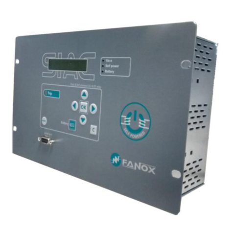
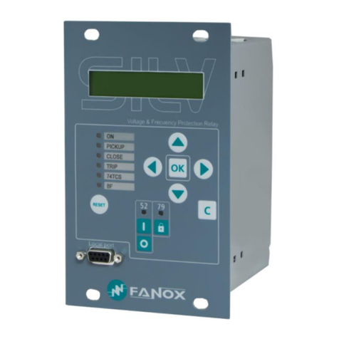
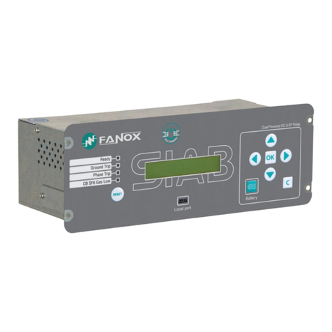
FANOX RELAYS
Our R+D Division has allowed FANOX to develop a wide range of easy-to-
install and operate electronic relays, at truly competitive prices, which will
save downtime and money.
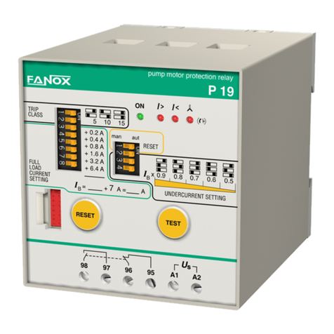
FANOX motor protection relays work with the current measured in real time.
The current, which is read by three current transformers built into the relays,
is electronically processed and used as a model of the thermal image of the
motor, and is continously compared to the values set on the relay.
The three power supply cables to the motor are not directly connected to
the relay, but pass through its corresponding CT holes.
This provides motor protection against:
• Overload: The relay creates a model of the thermal image of
the motor during its heating and cooling cycles. In this way, in
overload conditions, the relay will take into consideration previous
operating conditions of the motor, and will trip quicker if the
relay has detected previous occasions of overload. This thermal
memory is independent of the auxiliary voltage supply of the relay
and is stored even when this voltage is cut off or disconnected.
The different trip curves available for selection in the relays allow
for precise adjustment to any kind of motor start-up or work ing
cycle.
• Phase imbalance and phase loss: even if the motor is running
below its full load current.
• Incorrect phase sequence detection is highly important when the
correct phase sequence is critical as in compressors, pumps,
fans and other applications (GL, P, PF).
• Underload by undercurrent: protects the motor against working
without load, very important in pumps (P and PS).
• Protection against no-load operation: underload protection by
cos has been incorporated so that the relay differentiates
precisely between very low load and no-load operations, and
drops out in the latter case (PF).
In addition, when the relay is connected to thermistor sensors (PTC), it
protects the motor against electrical and non-electrical overheating (GL, G).
A visual display of the cause allows maintenance personnel to identify and
immediately act on the underlying causes. The use of the OD display makes
this operation much easier.
FANOX relays guarantee ideal protection for motors (pumps, compressors,
fans, etc).
Overtemperature (°C)
+5 +10 +15 +20
24.000
18.000
12.000
6.000
Life time hours
Installation and Adjustment guide

106
After installation and setup and before starting up the motor, make sure the motor is in a cold state. This will ensure that both the relay and motor, will operate
with the same thermal memory (cold condition).
C GL G PS P PF GEN
2.1 Select the trip class / tripping time 1st 1st 1st 1
st 1st 1st
2.2 Adjust the ,B current of the relay 2nd 2nd 2nd 1st 2nd 2nd 2nd
2.3 Adjust the cos value (underload) 3
rd
2.3 Adjust the cos trip delay 4
th
2.4 Adjust the undercurrent level ,< (underload) 2nd 3rd
2.5 Select ON /OFF incorrect phase sequence 3
rd
2.6 Reset 3rd 4th 3rd 3rd 4th 5th 3rd
2SETUP PROCEDURE
Correct order of steps during installation:
• After being fixed to the DIN rail, the
cables for the three phases should be
passed through the holes in the relay.
The maximum section of 700V insulated
wires that can pass through the holes
are:
• Assembly attached to other components:
it is recommended to separate the relays
of other units or items that could cause
strong magnetic fields, such as power
or control transformers, contactors,
frequency variators or high current
busbars.
• In star-delta starting, the relay or the
current transformers must be installed
between the fuses or circuit breaker and
the contactor.
• Relays used in combination with frequency inverters:
a) Not to be used with frequency inverters and fuel generators:
- GL relays if the protection against phase sequence selector is in the
“ON” position.
- P and PF relays.
b) The following can be used with frequency inverters and fuel
generators:
- GL relays if the protection against phase sequence selector is in the
“OFF” position.
- C, G and PS16-R.
Never connect the relay or current transformers of the auxiliary power
supply to the inverter output.
• Connection between the PTC sensors and the relay (GL and G). For PTC
connection lengths over 100 m or when the influence of high frequency
transient voltages is expected, it is adviseable to use screened cable and
connect the screen to terminal T1.
Note: every relay comes with an instruction manual providing information
on its correct installation and setup. Please follow this for guidance.
M
3
L1
L2
L3
1INSTALLATION
General
For correct installation and operation of Fanox relays, it is important to consider the following:
C 16 mm2
GL, P, PF, G, GEN 35 mm2
GL 200 70 mm2
Installation and Adjustment guide

107
2.1 Trip class / tripping time (IEC 947-4-1). Relays C, GL, P, PF, G and GEN
The different trip classes / tripping times enable the user to select the overload protection according to the various motor applications in either short or long
start-ups and for different generator uses.
The class number or the tripping time refers to the maximum approximate time in seconds allowed for the direct start of the motor from a cold condition.
To select the trip class or tripping time (t6 x ,B) use the corresponding dip switches. The recommended values are listed in the following tables.
Average trip curves (IEC 947-4-1)
Cold curve: represents
the performance of the
relay without any previous
current flow, first start.
Warm curve: the tripping
times decrease as the
current flows, and is
adapted to the motor
heating condition based
on the thermal memory.
The warm condition (IEC-
255) is reached after a
current of 0.9 x ,N(motor
rated current) flows during
approximately 2 hours.
Motor with star-delta start
Motor with direct start-up
C
P PF GEN
GL PSG
Start
time (s) Trip
time
Trip classes
Models Model
Trip classes
Start
time (s) Trip
time
Models Model
Generator’s limit curve

108
2.2 Current setting ,B. 2.3 Underload by cos . PF.
e.g.: relay GL16
,B=8+4 =12 A
21
)8//
/2$'
&855(17
6(77,
1*
,
%
$
7
5
,
3&/$666
RQRII
567
WR
21
21
,B = ,N x n
Installation and Adjustment guide
Relays C, GL, P, PF, G, BG and GEN
Adjust the current ,Bon the corresponding dipswitches (full load current).
When setting the current take into account that the base current of the relay
always remains added to the current selected with the dipswitches in “ON”
position (to the right). The total addition is the set current ,B.
Overload tripping current from 1,1 x ,B
a) For motor or generator rated currents (,N) within the range of the relay, the
setting ,Bmust be equal to the ,Nof the motor or generator.
,B = ,N
b) For motor rated currents below the range of the relay, the setting ,Bmust
be equal to the rated current of the motor ,Nmultiplied by the number
of times that the conductors have been passed through the relay holes.
c)
For motor or generator rated currents (,N) above the range of the relay, use
three current transformers .../5 in combination with the C9, GL16, P19,
PF16-R, G17, BG17 or GEN10 according to application.
With current transformers it is always a must to pass the conductors 2
times or more through the holes of the relay.
PS relay
This adjustment is to be made according to the nominal current of the motor
,
N
indicated in its characteristics plate. The value to be set ,Bis the same as
,
N
. The relay trips with overloads above 1,1 x IB ,
B
.
,B= ,N
The cos underload trip level is set by means of a potentiometer with
settings from 0,15 to 1,0.
Select this value taking into consideration the no-load motor cos and
that corresponding to the estimated minimum operating load. Choose an
intermediate value between these two cos levels and set it in the relay.
Select the underload trip delay from 5 to 45 seconds using the 3
corresponding dipswitches (trip delay).
For your guidance you can find two practical examples below.
a) A very oversized motor for its application. The cos of the motor is 0,15
when working without load.
b) A slightly oversized motor for its application. The cos of the motor is
0,25 when working without load.
If the above mentioned cos values are unknown, the underload trip setting
can be made in the following way:
1. Set the underload trip delay to zero by moving the three dipswitches
to the left (trip delay).
2. Using the potentiometer (cos setting), set the cos value to the
minimum: 0,15.
3. Set the reset time to the minimum value using the potentiometer
(cos reset time).
4. Start up the motor and run it with the minimum estimated load.
5. Slowly turn the cos potentiometer clockwise until the relay trips and
the cos LED lights up.
6. Turn the cos potentiometer anticlockwise until the cos is set at
approximately 30% less than the previous value (point 5).
7. Set the underload trip delay using the 3 corresponding dip switches.
Set the reset time using the adequate potentiometer.
Nominal
load
Estimated
minimum load
Approximated cos
adjustement area
cos
No-load
Nominal
load
Estimated
minimum load
Approximated cos
adjustement area
cos
No-load
always n ≥ 2
,B=,Nmotor x 5 x n
,Ntrafo

109
2.4 Undercurrent.
Single phase relay PS
The setting of the underload trip level is made using a potentiometer in wich
a factor between 0,4 and 0,9 is to be chosen. By multiplying this factor by
the adjusted ,Bwe obtain a current value under which the relay will trip and
disconnect the motor. The trip is delayed by 5 seconds.
a) If the value of the ,Bof the motor without load is known:
• To avoid unwanted trips it is recommended to adjust the value 15%
above the ,Bof the motor without load.
Example:
b)
If the value of the ,Bof the motor without load is unknown:
• If the pump is adequately dimensioned, the recommended value for
this factor is 0,7. Adjust the potentiometer “undercurrent” to 0,7.
• If the pump is excessively dimensioned, and during its operation
unwanted trips could occur, the underload adjusted factor should be
reduced to approximately 0,6.
Three phase relay P
The undercurrent trip level in P relays is set using three dipswitches. To
avoid nuisance trips, set this level to approximately 10% above the no-load
motor current.
Example:
2.5 Phase sequence
Monitoring the current. GL and P relays
An incorrect phase sequence is detected by current sensing and it is only
operative during the motor start-up. For correct detection the starting time
must be longer than 0.2 s.
In GL relays the user can activate or desactivate this protection by means
of a dipswitch. Should the right phase sequence be critical, move the
dipswitch to the “ON” position. If this protection is not required, always leave
it in the “OFF” position.
As this function is not compatible with the use of frequency inverters, where
it is necessary to protect phase sequence in these installations, move the
dipswitch to “OFF” and install the Fanox “S” model relay.
Monitoring the voltage. PF relays
An incorrect phase sequence is detected by voltage monitoring.
In the event that an incorrect phase sequence has been detected, the
motor will not start-up since the relay has tripped because of previously
detecting the wrong phase sequence.
• Dry running
• Dry running
0.6 x 1.1 = 0.66
x1.1

110
2.6 Reset 3OPERATING TEST. C, GL, P, PF, G and GEN
To perform the trip test for phase loss, the current which passes through the
relay must be higher than 0.7 of the set current ,B.Under these conditions,
push and hold the TEST button for three seconds, the relay will trip due to
phase loss and the corresponding LED will light up.
4APPLICATIONS
Industries
• OEM (Original Equipment Manufacturers)
• Chemical and petrochemical
• Quarries, gravel pits and cement factories
• Steelworks, iron and steel industry
• Automotive
• Utilities and electric generation
• Water treatment and distribution
• Mining
• Food industry, sugar industry
• Marine and shipbuilding
• Timber industry
• Elevation industry
• HVAC (Heat Ventilation Air Condition)
Installations
• Motor Control Centers (MCC)
• EEx e motors in explosive environments
• Submergible pumps, in service stations and water pumping, surface
pumps, etc
• Compressors
• Fans, blowers and ventilators
• Industrial refrigeration and air conditioning
• Centrifuges
• Presses
• Cranes, elevators, escalators and lifting machinery
• Machine tool
• Conveyor belts
• Mills and mixers
• Generators and alternators.
It is necessary to disconnect the auxiliar voltage more than 3 seconds after
having waited the time indicated in the table.
Relays manual remote autom.
C, GL, G, GEN ••
P, PF man man auto
PS ••
PS P PF C GL G GEN
NO <5 m <7 m <8 m <8 m <8 m <1 m
NO2s-----
cos
--NO----
- 2 s 2 s (*) 2 s 2 s 2 s 2 s
- 2 s 2 s (*) 2 s 2 s - -
NO------
----1s(*)1s(*)-
PS P PF C GL G GEN
<1 m <1 m <3 m <3 m <3 m <3 m <1 m
10s10s-----
cos
--10s----
- 10 s 10 s 20 s 20 s 10 s 10 s
- 10 s 10 s 10 s 10 s - -
NO------
----1s(*)1s(*)-
PS P PF C GL G GEN
4m15m 4m NONONONO
PS11-R 2-70 m 15 m
--
---
PS16-R 2-240 m
cos
- - 2-75m - -
- 15 m 4 m (*) NO NO NO NO
- 15 m 4 m (*) - NO - -
1s(*)- - ----
- - - - NO NO -
Manual reset:
Remote reset:
Automatic reset:
(*) After recovering normal conditions.
Installation and Adjustment guide
111
Selection guide
5NOMINAL CURRENT RATING OF ASYNCHRONOUS THREE-PHASE MOTORS
The current values listed in the following table correspond to the average ratings given by various manufacturers. In some cases, these may not
coincide exactly with the ratings listed on the motor data plates.
kW 0,75 1,1 1,5 2,2 3 3,7 4 5,5 7,5 11 15 18,5 22 30 37 45 55 75 90 110
CV 11,523455,57,5101520253040506075100125150
IN
(A)
Average
values
MOTOR
4P
230 V
50Hz 3,5 5 6,5 9,5 11 – 15 22 28 42 54 68 80 104 130 154 192 248 312 360
400 V
50Hz 2 2,5 3,5 5 6,5 – 8,5 11 15 22 29 35 42 57 69 81 100 131 162 195
440 V
50Hz 1,7 2,4 3,2 4,5 6 – 8 10,5 14 20 27 33 39 52 64 76 91 120 147 178
220/240 V
60Hz 3,2 4,4 6,2 8,5 10,5 – 14 20 26 38 50 63 74 98 122 146 180 233 290 345
440/460 V
60Hz 1,5 2,2 3 4,3 5,5 – 7,5 10 13 19 25 31 37 49 61 73 90 116 144 173
MOTOR
2P
400 V
50Hz 2,0 2,8 3,8 5,5 7 – 9,5 13 16,5 24 32 40 47 64 79 92 113 149 183 220
440/460 V
60Hz 1,9 2,5 3,4 4,8 6 7,5 – 11 15 21 27 33 39 53 65 79 95 120 153 183
MODELS
Adjustment
range
,B
(A)
MOTOR CHARACTERISTICS 400V PROTECTION FUNCTIONS
HP kW
cos
C 9 3 - 9,3 2 - 5,5 1,5 - 4 • •
C 21 9 - 21,6 7,5 - 12 5,5 - 9 • •
C 45 20 - 45,2 15 - 30 11 - 22 • •
GL 16 4 - 16,7 3 - 10 2,2 - 7,5 • •
ON
•
GL 40 15 - 40,5 10 - 25 7,5 - 18,5 • •
ON
•
GL 90 40 - 91 30 - 60 22 - 45 • •
ON
•
GL 200 60 - 200 50 - 150 37 - 110 • •
ON
•
PS 11-R 3 - 11 0,5 - 2 0,37 - 1,5 • • •
PS 16-R 3 - 16 0,5 - 3 0,37 - 2,2 • • •
P 19 7 - 19,6 4 - 10 3 - 7,5 • • • •
P 44 19 - 44,2 12,5 - 27,5 9,2 - 20 • • • •
P 90 40 - 90,4 27,5 - 55 20 - 40 • • • •
PF 16-R 4 - 16,6 3 - 10 2,2 - 7,5 • • • •
PF 47-R 16 - 47,5 10 - 30 7,5 - 22 • • • •
G 17 5 - 17,7 3 - 10 2,2 - 7,5 • • •
GEN 10 4 - 10,3 - - • •
MODELS
Adjustment
range
,B
(A)
MOTOR CHARACTERISTICS 400V PROTECTION FUNCTIONS
HP kW
JAM ,J,R
PBM B1 0,8 - 6 0,33 - 3 0,25 - 2,2 •••••••
PBM B5 4 - 25 3 - 15 2,2 - 11 •••••••
Overload Undercurrent Underload Phase loss Phase sequence Overtemperature Overvoltage / Loss of neutral Locked JAM Earth leakage:
Phase imbalance Undervoltage rotor differential/homopolar
cos
N,J,R
JAM
• Motor management system
• Protection relays
This manual suits for next models
57
Table of contents
Other FANOX Relay manuals

FANOX
FANOX SIL-V User manual

FANOX
FANOX SIA-B Series User manual

FANOX
FANOX SIA-B Standard CTs User manual

FANOX
FANOX SIA F User manual

FANOX
FANOX SIA-B Standard Series User manual

FANOX
FANOX SIA-B User manual

FANOX
FANOX SIA-C User manual

FANOX
FANOX SIL-G User manual

FANOX
FANOX SIL-A User manual

FANOX
FANOX P Series User manual