Dembla GTV - 01 Series User manual

Instruction Manual
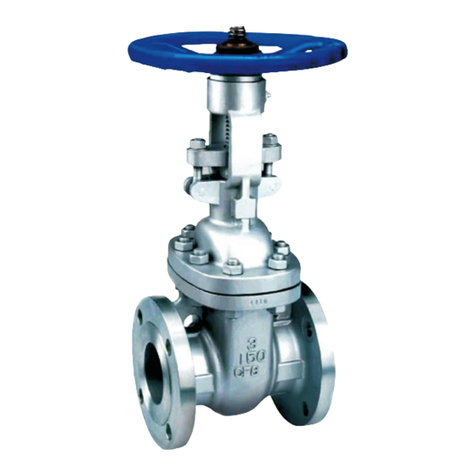
Gate Valve
Series GTV-01

CONTENTS PAGE NO.
1.0 Introduction 2
3
3
2.1 Protection
2.2 Storage
2.3 Transportation
3
3
2.0 Storage&Transportation
3
3
3
3
3.1 Witness Viewing
3.2 Fitness of flange and pipeline
3.3 Installation 4
4.0 Opearation 5
1
3.0 Installation to the pipeline
5.0 Maintenance 6
5.1 Daily Maintenance
5.2 Possible Fault&Solution
5.3 Replacement of wedge
5.4 Replacement of Gasket
5.5 Replacement of Stem O ring Seal
5.6 Replacement of Gland O ring
6
6
6
7
7

Instruction for use
Thanks for selecting our product. With correct use, it will give long and reliable service. This manual
has been prepared to assist you install, operate and maintain the valve to the maximum efficiency.
For easy of reference, it has been divided into sections covering all aspects of use, and it is the users
best interests to read it and ensure that it is fully understood.
Health and Safety
It is always recommended that wherever work is being carried out on a valve that the valve is fully depressured
prior to carrying it out, and for the convenience draining of the line may be beneficial. It is essential that the user
of the valve is aware of the weight of the components and/or assembles that must be handled and manipulated
during installation and maintenance. It is the users responsibility to ensure that safe working practices are followed
at all times. Whenever our products are installed, operated, or maintained, it is essential that the staff that
undertake these operations be adequately trained. The hazards of pressurised liquids can be served, and it is the
responsibility of the users to ensure that trained, competent staff undertake these duties. This manual has been
designed to assist, but it can never fully replace quality training in the workplace. Our technical staff will always
be available to answer any questions relating to specific problems that may not be covered by this manual.
Our products are designed and manufactured to be fit for purpose, and to a high and reliable standard. This
provides a safe product with minimum risk to health when used correctly for the purpose for which it was designed.
However, this assumes that the equipment is used and maintained in accordance with the manual, and the user is
advised to study this manual, and to make it available to all staff that may need to refer to it.
We cannot be held responsible for any incidents arising from incorrect installation, operation or maintenance. The
responsibility for this must be rest wholly with the user.
1. Introduction
We provides the resilient seat gate valve from DN50 to DN1200. The vertical or horizontal installation is
recommended. The valve can also be installed independent of the flow direction.
All gate valves are 100% tested in factory before shipping.
Sectional drawing and components list
2

2. Storage&Transportation
2.1 Protection
Delivery of valve should be strictly under"engineering instruction" protection requirements, to ensure that the
flange surface, disc sealing ring from harm.
2.2 Storage
If the valves need to be stored before installation for some time, they should be kept in the wooden (wicker) boxes
of the original delivery, off the ground in a dry and clean indoor area.
2.3 Transportation
2.3.1 Packed Valves
Take out the valve from the wooden box or others, If the valve can not be carried by one person (over 25Kgs)
,then
should use certain equipment to lift and carry the packed valves, and hook on to them in specified position (or
proper position).
All packaging materials comply with local safety regulations and requirements to ensure safe transportation.
2.3.2 Unpacked Valves
Use appropriate method to lift and transport the unpacked valves and within the carrying limit by tray and protect
the machined surface ( flange) from damage. Meanwhile, the rope for lifting should keep certain distance from the
valve body to prevent breaking paint. When lifting large diameter valves, use proper tools to load and lift them
(like tray, hook, fastener, etc), and with loading balance tools, to avoid sliding or moving during the lifting and
carrying. If lifting by a excavator, use proper method to protect the complete valve to avoid damage.
3. Installation to the pipeline
Warning!
■ The installation and setting up operator should use appropriate equipment and required to wear
personal protective equipment.
■ Must relief the pipeline pressure before installation
■ Only qualified staff after mechanically trained could install the valves.
■It is forbidden to climb through the valves or its components,or to crane by valves or hand
wheel.
■ Verify the pipe pressure and temperature limits are within the application standard of the
valves.
■ Verify the fitness between the fluid media through the pipeline and application field of the
valve.
3.1 Witness Viewing
3.1.1 Carefully take out the valve from the package without damage, including the valve body, hand wheel etc...
3.1.2 Check the materials shown in the rating label are suitable, as well as the using temperature and pressure., if
no rating label, this valve is for general water service under PN16 ( or PN25) and 0-80°C
3.1.3 Forbidden to use the components from third party, to keep long service life of the valves.
3.2 Fitness of flange and pipeline
Before installation, check the sealing method and drilling between valves and pipeline.
3

Bolt list:
DN
PN
Bolts
Quantity
DN
PN
Bolts
Quantity
100
16
M16
8
150
16
M20
8
200
16
M20
12
250
16
M24
12
300
16
M24
12
350
16
M24
16
400
16
M27
16
450
16
M27
20
500
16
M30
20
600
16
M33
20
700
16
M33
24
750
16
M36
24
800
16
M36
24
900
16
M36
28
1000
16
M39
28
1200
16
M45
32
3.3 Installation
Importance Notice.
■ Must clear up the trash in the pipeline before installation.
■ Take off the protection materials from the valves.
■ Avoid to put valve in the middle of two flanges, then weld the flanges ( for those connection
with carbon steel pipe ), which would burn the rubber and cause leakage.
■ The passageway center of the valve should align the center of the pipeline.
■ To avoid heat or solder rubbish dropping on the wedge, during installation, if possible, should
take measures to protect the wedge.
■ Dry friction will variate the resilient seat, do not open or close the valve after installation
before flow media goes through.
■ After installation, should keep the valve in fully open position, and to clear up the solder
rubbish in the pipeline with flushing many times, to avoid damage to the wedge.
■ After installation, never use the valve as supporter to the pipeline.
3.3. 1 Extension stem installation
Before installation if the extension stem and gearbox were packed separately, assemble the extension stem and
gearbox firstly.
3.3.1.1 Take out the extension stem from package. Connect the extension with valve bare stem by key or square
head.
3.3.1.2 Take out the protection tube from package. Pass the extension stem through the protection tube and connect
the protection tube flange with bare stem valve top flange by bolts.
3.3.1.3 If there are two pieces or more extension stem, take out the next extension stem from package. Connect the
extension with first extension stem by connector
3.3.1.4 Take out the next protection tube from package. Pass the second extension stem through the protection tube
and connect the protection tube flange with first one by bolts. And repeat 3.3.1.3 &3.3.1.4 if have more extension
stem needed.
3.3.1.5 Fix the gear box with top flange of the protection tube by bolts. Gearbox connect with the extension stem
by key.
3.3.1.6 If use hand wheel operated directly, Fix the hand wheel in the top of the extension stem.
4

3.3. 2 Extension stem disassembly
3.3.2.1 Remove the bolts between gearbox and top flange of the protection tube.
3.3.2.2 Remove the gearbox.
3.3.2.3 Remove the bolts between flange of the protection tube and valve top flange
3.3.2.4 Remove the protection tube.
3.3.2.5 Remove the extension stem and key (If have).
3.3.2.5 If there are two pieces or more extension stem, remove the bolts between two flanges of the protection
tube.
3.3.2.6 Remove the protection tube.
3.3.2.7 Remove the extension stem and connector. Repeat 3.3.2.5 to 3.3.2.7 until remove the extension stem from
the valve bare stem
3.3. 3 Importance Notice.
To check if the matching flange surface in good status, no trash in the wedge, no damage during the delivery, and
the pipeline is already clear.
3.3.3.1 Ensure the distance between end flanges of two pipelines enough for installation.
3.3.3.2 Ensure the seats and the flanges are clean when installing the gate valve.
3.3.3.3 Select the correct type of gasket. Gaskets with the correct flange size must be used.
3.3.3.4 When valves are provided with lifting lugs, plates or eye nuts, there must be used to lift the valve.
3.3.3.5 Place valves between pipe flanges and insert the bolts..
3.3.3.6 Tighten the bolt loosely..
3.3.3.7 Tighten the bolt in diagonal sequence to make sure flanges are pulled parallel.
3.3.3.8 To fasten the bolts in cross direction with proper torque.
4 Operation
General
The gate valve is suitable for use with water or neutral liquids from 0°C to 80°C. Insulation is essential for external
temperature from 0°C to -10°C. The gate valve can be operated by either hand wheel, gearbox or electrical
actuator.
4.1 Operation Direction
4.1.1 Valve closing: Operate the stem in clockwise direction.
4.1.2 Valve opening: Operate the stem in counter clockwise direction.
4.2 Possible risk:
4.2.1 Mechanical: If operate the valve manually, ensure there is enough space to operate the valve to avoid hand
clamping.
4.2.2 Electric: Since the static electricity could cause the explosion, the valve should be ground connection.
4.2.3 Temperature: If the outside temperature is below 5 ℃ or above 40 ℃, the valve surface will be very cold or
hot, should take shield to protect the internal components of the valve, like O-ring, rubber kits, etc. People who
operate the valve should be with protection.
4.2.4 Operational: If close the valve too fast, there will be water hammer come from the upstream. And the the
water hammer may damage the valve. In any case, should avoid the water hammer.
5

5. Maintenance
Our valve only need the minimum maintenance and no lubrication is required.
Warning!
■ Before open the valve bonnet-relief pressure first and drain the water and pressure by un-fasten
flange bolts. Any maintenance to the valve must be under condition that the valve inside is
fully pressure reliefing to avoid any damage to the worker.
■ Any repair in the condition with media, pressure or temperature, should get approval of
specialist, and set up working guidance.
■ Before disassemble the valve, must ensure that the media left should have no harm to the
operator or equipment, and in proper repair temperature.
■ All the adjustment and repair operators should use proper equipment and wear job safety
wares.
■ Only qualified staff after mechanically trained could adjust and repair the valves.
5.1 Daily Maintenance:
Except the routine view inspection to ensure the satisfactory operation and sealing, no need the daily maintenance
and lubricant.
5.2. Possible Fault&Solution
Malfunctions
Causes
Troubleshooting
Could not close the valve
Rubbish in the valve interior
Clean the rubbish
Internal leakage-wedge leak
Not close completely
Use higher torque to close
Damage of rubber wedge/O ring
Change rubber
Wedge/ O ring
Outside leaking from bonnet
gasket
Rupture of gasket
Replace new gasket
Leakage from stem
Rupture of O ring seal
Replace all the top O ring
Leakage from gland
Rupture of gland O ring
Replace the O ring
5.3 Replacement of wedge
5.3.1 Isolate valve and ensure there is no pressure in the pipeline.
5.3.2 Counter clockwise stem to put the wedge into slightly open position.
5.3.3 Remove hot melt cover to expose the hex bolt. Then remove the bolts.
5.3.4 Lift the entire bonnet assembly and wedge from the valve body.
5.3.5 Unscrew wedge from the stem.
5.3.6 Fit new wedge on wedge nut.
5.3.7 Put the bonnet assembly with wedge into valve body.
6

5.3.8 Tighten the hex bolt on the bonnet.
5.3.9 The hot cover on the hex bolt is suggested, but not necessary.
5.4 Replacement of Gasket
5.4.1 Isolate valve and ensure there is no pressure in the pipeline
5.4.2 Counter clockwise stem to put the wedge into slightly open position.
5.4.3 Remove hot melt cover to expose the hex bolt. Then remove the bolts.
5.4.4 Lift the entire bonnet assemble and wedge up from the valve body.
5.4.5 Replace the gasket on the valve body..
5.4.6 Put the bonnet assembly with wedge into valve body.
5.4.7 Tighten the hex bolt on the bonnet.
5.4.9 The hot cover on the hex bolt is suggested, but not necessary.
5.5 Replacement of Stem O ring Seal
5.5.1 Isolate valve and ensure there is no pressure in the pipeline.
5.5.2 Remove hot melt cover to expose the hex bolt. Then remove the bolts.
5.5.3 Lift the entire gland assembly from bonnet.
5.5.4 Lift the entire bonnet assembly and wedge from the valve body.
5.5.5 Unscrew wedge and wedge nut from the stem.
5.5.6 Take out the stem from the bonnet and then replace the pair of O-ring on the stem.
5.5.7 Put the stem into bonnet.
5.5.7 Screw wedge and wedge nut on the stem.
5.5.8 Put the bonnet assembly with wedge into valve body.
5.5.9 Tighten the hex bolt on the bonnet.
5.5.10 Put the gland assembly on the top of the bonnet.
5.5.11 Tighten the hex bolt.
.
5.6 Replacement of Gland O ring
5.6.1 Remove hot melt cover to expose the hex bolt. Then remove the bolts.
5.6.2 Lift the entire gland assembly from bonnet.
5.6.3 Replace the O-Ring in the gland.
5.6.4 Put the gland assembly on the top of the bonnet.
5.6.5 Tighten the hex bolt.
7

Dembla
Sales Office: Works:
M/S. Dembla Valves Ltd.
C-30, Jai Matadi Compound, Kalher
Village,Thane-Bhiwandi-Agra Raod -
421302,
Maharashtra,India.
Tel - +91-9292234790 - 97
E-mail - [email protected]
More info - www.dembla.com
M/S. Dembla Valves Ltd.
A/8, Arahm Logistic, Valshind Village,
Mumbai -Nashik Highway
(NH3),Bhiwandi
Thane - 421302. Maharashtra (India)
Dembla Valves |
Other manuals for GTV - 01 Series
1
Table of contents
Other Dembla Control Unit manuals
Popular Control Unit manuals by other brands

Densitron
Densitron DD-12832 1A Series Application notes
Automationdirect.com
Automationdirect.com Stride SIOL-EI8B user manual
Carrier
Carrier Touch Pilot manual
WAREMA
WAREMA Minitronic Dialog Operating and installation instructions

ACS
ACS ACM1281U-C7 Reference manual

SEW-Eurodrive
SEW-Eurodrive MOVIAXIS MXR manual

Patton
Patton 3101RC quick start guide

Emerson
Emerson Dixell XEC Supercap Installing and operating instructions

Siemens
Siemens SINUMERIK 840D sl Programming manual

ABB
ABB REF 542plus installation manual
CLA-VAL
CLA-VAL 50B-4KG1 Installation, operation and maintanance manual
Graco
Graco ProMix Auto Installation

